
G 14DMR - Grinder HiKOKI - Free user manual and instructions
Find the device manual for free G 14DMR HiKOKI in PDF.


| Product Type | Cordless Disc Grinder |
| Brand | HiKOKI |
| Model | G14DMR |
| Voltage | 14.4 V |
| Rated Speed | 9300 min⁻¹ |
| Wheel Outer Diameter | 115 mm |
| Wheel Hole Diameter | 22.23 mm |
| Maximum Wheel Peripheral Speed | 80 m/s |
| Weight | 2.1 kg |
| Power Source | Rechargeable battery (14.4 V) |
| Compatible Battery Types | Ni-Cd (EB14B), Ni-MH (EB1426H, EB1430H, EB1433X), Li-ion (BCL1430, EBL1430) |
| Compatible Chargers | UC14YFA, UC24YFA |
| Battery Capacity Options | 2.0 Ah, 2.6 Ah, 3.0 Ah, 3.3 Ah |
| Charging Time (3.0 Ah Ni-MH) | 70 min (UC14YFA/UC24YFA) |
| Overload Protection | Yes (electronic shutdown) |
| Safety Guard | Adjustable wheel guard |
| Side Handle | Screw-on side handle included |
| Spindle Lock | Push button for wheel changes |
| A-Weighted Sound Pressure Level | 74 dB(A) |
| A-Weighted Sound Power Level | 85 dB(A) |
| Vibration Emission (Surface Grinding) | 9.3 m/s² (K=1.5 m/s²) |
| Carbon Brush Replacement | Yes, HiKOKI Code No. 999054 |
| Applications | Grinding, cutting, finishing of metal, stone, concrete, etc. |
| Standard Accessories | Depressed center wheel, wrench, side handle, charger, battery, plastic case |
Frequently Asked Questions - G 14DMR HiKOKI
User questions about G 14DMR HiKOKI
0 question about this device. Answer the ones you know or ask your own.
Ask a new question about this device
Download the instructions for your Grinder in PDF format for free! Find your manual G 14DMR - HiKOKI and take your electronic device back in hand. On this page are published all the documents necessary for the use of your device. G 14DMR by HiKOKI.
USER MANUAL G 14DMR HiKOKI
Batteridriven vinkelslip Batteri vinkelsliber Batteridrevet vinkelsliper Akkutoiminen kulmahiomakone Cordless Disc Grinder
G 14DMR • G 14DL G 18DMR • G 18DL
natural_image
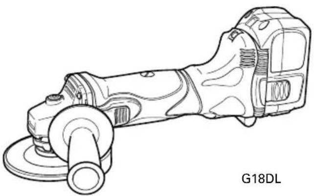
Line drawing of a mechanical power tool with a cast, labeled G18DL (no other text or symbols)Read through carefully and understand these instructions before use.
1
2
4
6
natural_image
Line drawing of a hand using a power tool to work on a mechanical grinding machine (no text or symbols present)3
5
7
VEDLIKEHOLD OG INSPEKSJON
Read all safety warnings and all instructions.
Failure to follow the warnings and instructions may result in electric shock, fire and/or serious injury.
Save all warnings and instructions for future reference.
The term "power tool" in the warnings refers to your mains-operated (corded) power tool or battery-operated (cordless) power tool.
1) Work area safety
a) Keep work area clean and well lit.
Cluttered or dark areas invite accidents.
b) Do not operate power tools in explosive atmospheres, such as in the presence of flammable liquids, gases or dust.
Power tools create sparks which may ignite the dust or fumes.
c) Keep children and bystanders away while operating a power tool.
Distractions can cause you to lose control.
2) Electrical safety
a) Power tool plugs must match the outlet.
Never modify the plug in any way.
Do not use any adapter plugs with earthed (grounded) power tools.
Unmodified plugs and matching outlets will reduce risk of electric shock.
b) Avoid body contact with earthed or grounded surfaces, such as pipes, radiators, ranges and refrigerators.
There is an increased risk of electric shock if your body is earthed or grounded.
c) Do not expose power tools to rain or wet conditions.
Water entering a power tool will increase the risk of electric shock.
d) Do not abuse the cord. Never use the cord for carrying, pulling or unplugging the power tool. Keep cord away from heat, oil, sharp edges or moving parts.
Damaged or entangled cords increase the risk of electric shock.
e) When operating a power tool outdoors, use an extension cord suitable for outdoor use.
Use of a cord suitable for outdoor use reduces the risk of electric shock.
f) If operating a power tool in a damp location is unavoidable, use a residual current device (RCD) protected supply.
Use of an RCD reduces the risk of electric shock.
3) Personal safety
a) Stay alert, watch what you are doing and use common sense when operating a power tool. Do not use a power tool while you are tired or under the influence of drugs, alcohol or medication.
A moment of inattention while operating power tools may result in serious personal injury.
b) Use personal protective equipment. Always wear eye protection.
Protective equipment such as dust mask, non-skid safety shoes, hard hat, or hearing protection used for appropriate conditions will reduce personal injuries.
c) Prevent unintentional starting. Ensure the switch is in the off position before connecting to power source and/or battery pack, picking up or carrying the tool.
Carrying power tools with your finger on the switch or energising power tools that have the switch on invites accidents.
d) Remove any adjusting key or wrench before turning the power tool on.
A wrench or a key left attached to a rotating part of the power tool may result in personal injury.
e) Do not overreach. Keep proper footing and balance at all times.
This enables better control of the power tool in unexpected situations.
f) Dress properly. Do not wear loose clothing or jewellery. Keep your hair, clothing and gloves away from moving parts.
Loose clothes, jewellery or long hair can be caught in moving parts.
g) If devices are provided for the connection of dust extraction and collection facilities, ensure these are connected and properly used.
Use of dust collection can reduce dust related hazards.
4) Power tool use and care
a) Do not force the power tool. Use the correct power tool for your application.
The correct power tool will do the job better and safer at the rate for which it was designed.
b) Do not use the power tool if the switch does not turn it on and off.
Any power tool that cannot be controlled with the switch is dangerous and must be repaired.
c) Disconnect the plug from the power source and/or the battery pack from the power tool before making any adjustments, changing accessories, or storing power tools.
Such preventive safety measures reduce the risk of starting the power tool accidentally.
d) Store idle power tools out of the reach of children and do not allow persons unfamiliar with the power tool or these instructions to operate the power tool.
Power tools are dangerous in the hands of untrained users.
e) Maintain power tools. Check for misalignment or binding of moving parts, breakage of parts and any other condition that may affect the power tools operation.
If damaged, have the power tool repaired before use.
Many accidents are caused by poorly maintained power tools.
f) Keep cutting tools sharp and clean.
Properly maintained cutting tools with sharp cutting edges are less likely to bind and are easier to control.
g) Use the power tool, accessories and tool bits etc. in accordance with these instructions, taking into account the working conditions and the work to be performed.
Use of the power tool for operations different from those intended could result in a hazardous situation.
5) Battery tool use and care
a) Recharge only with the charger specified by the manufacturer.
A charger that is suitable for one type of battery pack may create a risk of fire when used with another battery pack.
b) Use power tools only with specifically designated battery packs.
Use of any other battery packs may create a risk of injury and fire.
c) When battery pack is not in use, keep it away from other metal objects like paper clips, coins, keys, nails, screws, or other small metal objects that can make a connection from one terminal to another.
Shorting the battery terminals together may cause burns or a fire.
d) Under abusive conditions, liquid may be ejected from the battery; avoid contact. If contact accidentally occurs, flush with water. If liquid contacts eyes, additionally seek medical help. Liquid ejected from the battery may cause irritation or burns.
6) Service
a) Have your power tool serviced by a qualified repair person using only identical replacement parts.
This will ensure that the safety of the power tool is maintained.
PRECAUTION
Keep children and infirm persons away.
When not in use, tools should be stored out of reach of children and infirm persons.
SAFETY WARNINGS COMMON FOR GRINDING OR ABRASIVE CUTTING-OFF OPERATIONS
a) This power tool is intended to function as a grinder or cut-off tool. Read all safety warnings, instructions, illustrations and specifications provided with this power tool.
Failure to follow all instructions listed below may result in electric shock, fire and/or serious injury.
b) Operations such as sanding, wire brushing or polishing are not recommended to be performed with this power tool.
Operations for which the power tool was not designed may create a hazard and cause personal injury.
c) Do not use accessories which are not specifically designed and recommended by the tool manufacturer.
Just because the accessory can be attached to your power tool, it does not assure safe operation.
d) The rated speed of the accessory must be at least equal to the maximum speed marked on the power tool.
Accessories running faster than their rated speed can break and fly apart.
e) The outside diameter and the thickness of your accessory must be within the capacity rating of your power tool.
Incorrectly sized accessories cannot be adequately guarded or controlled.
f) The arbour size of wheels, flanges, backing pads or any other accessory must properly fit the spindle of the power tool.
Accessories with arbour holes that do not match the mounting hardware of the power tool will run out of balance, vibrate excessively and may cause loss of control.
g) Do not use a damaged accessory. Before each use inspect the accessory such as abrasive wheels for chips and cracks, backing pad for cracks, tear or excess wear, wire brush for loose or cracked wires. If power tool or accessory is dropped, inspect for damage or install an undamaged accessory. After inspecting and installing an accessory, position yourself and bystanders away from the plane of the rotating accessory and run the power tool at maximum no-load speed for one minute.
Damaged accessories will normally break apart during this test time.
h) Wear personal protective equipment. Depending on application, use face shield, safety goggles or safety glasses. As appropriate, wear dust mask, hearing protectors, gloves and workshop apron capable of stopping small abrasive or workpiece fragments.
The eye protection must be capable of stopping flying debris generated by various operations. The dust mask or respirator must be capable of filtrating particles generated by your operation.
Prolonged exposure to high intensity noise may cause hearing loss.
i) Keep bystanders a safe distance away from work area. Anyone entering the work area must wear personal protective equipment.
Fragments of workpiece or of a broken accessory may fly away and cause injury beyond immediate area of operation.
j) Hold power tool by insulated gripping surfaces only, when performing an operation where the cutting accessory may contact hidden wiring or its own cord.
Cutting accessory contacting a "live" wire may make exposed metal parts of the power tool "live" and shock the operator.
k) Position the cord clear of the spinning accessory. If you lose control, the cord may be cut or snagged and your hand or arm may be pulled into the spinning accessory.
I) Never lay the power tool down until the accessory has come to a complete stop.
The spinning accessory may grab the surface and pull the power tool out of your control.
m) Do not run the power tool while carrying it at your side.
Accidental contact with the spinning accessory could snag your clothing, pulling the accessory into your body.
n) Regularly clean the power tool's air vents.
The motor's fan will draw the dust inside the housing and excessive accumulation of powdered metal may cause electrical hazards.
o) Do not operate the power tool near flammable materials.
Sparks could ignite these materials.
p) Do not use accessories that require liquid coolants.
Using water or other liquid coolants may result in electrocution or shock.
KICKBACK AND RELATED WARNINGS
Kickback is a sudden reaction to a pinched or snagged rotating wheel, backing pad, brush or any other accessory. Pinching or snagging causes rapid stalling of the rotating accessory which in turn causes the uncontrolled power tool to be forced in the direction opposite of the accessory's rotation at the point of the binding.
For example, if an abrasive wheel is snagged or pinched by the workpiece, the edge of the wheel that is entering into the pinch point can dig into the surface of the material causing the wheel to climb out or kick out. The wheel may either jump toward or away from the operator, depending on direction of the wheel's movement at the point of pinching. Abrasive wheels may also break under these conditions.
Kickback is the result of power tool misuse and/or incorrect operating procedures or conditions and can be avoided by taking proper precautions as given below.
a) Maintain a firm grip on the power tool and position your body and arm to allow you to resist kickback forces. Always use auxiliary handle, if provided, for maximum control over kickback or torque reaction during start-up.
The operator can control torque reactions or kickback forces, if proper precautions are taken.
b) Never place your hand near the rotating accessory. Accessory may kickback over your hand.
c) Do not position your body in the area where power tool will move if kickback occurs.
Kickback will propel the tool in direction opposite to the wheel's movement at the point of snagging.
d) Use special care when working corners, sharp edges etc. Avoid bouncing and snagging the accessory. Corners, sharp edges or bouncing have a tendency to snag the rotating accessory and cause loss of control or kickback.
e) Do not attach a saw chain woodcarving blade or toothed saw blade.
Such blades create frequent kickback and loss of control.
SAFETY WARNINGS SPECIFIC FOR GRINDING AND ABRASIVE CUTTING-OFF OPERATIONS
a) Use only wheel types that are recommended for your power tool and the specific guard designed for the selected wheel.
Wheels for which the power tool was not designed cannot be adequately guarded and are unsafe.
b) The guard must be securely attached to the power tool and positioned for maximum safety, so the least amount of wheel is exposed towards the operator.
The guard helps to protect operator from broken wheel fragments and accidental contact with wheel.
c) Wheels must be used only for recommended applications. For example: do not grind with the side of cut-off wheel.
Abrasive cut-off wheels are intended for peripheral grinding, side forces applied to these wheels may cause them to shatter.
d) Always use undamaged wheel flanges that are of correct size and shape for your selected wheel.
Proper wheel flanges support the wheel thus reducing the possibility of wheel breakage. Flanges for cut-off wheels may be different from grinding wheel flanges.
e) Do not use worn down wheels from larger power tools.
Wheel intended for larger power tool is not suitable for the higher speed of a smaller tool and may burst.
ADDITIONAL SAFETY WARNINGS SPECIFIC FOR ABRASIVE CUTTING-OFF OPERATIONS
a) Do not "jam" the cut-off wheel or apply excessive pressure. Do not attempt to make an excessive depth of cut.
Overstressing the wheel increases the loading and susceptibility to twisting or blinding of the wheel in the cut and the possibility of kickback or wheel breakage.
b) Do not position your body in line with and behind the rotating wheel.
When the wheel, at the point of operation, is moving away from your body, the possible kickback may propel the spinning wheel and the power tool directly at you.
c) When wheel is binding or when interrupting a cut for any reason, switch off the power tool and hold the power tool motionless until the wheel comes to a complete stop. Never attempt to remove the cut-off wheel from the cut while the wheel is in motion otherwise kickback may occur.
Investigate and take corrective action to eliminate the cause of wheel binding.
d) Do not restart the cutting operation in the workpiece. Let the wheel reach full speed and carefully reenter the cut.
The wheel may bind, walk up or kickback if the power tool is restarted in the workpiece.
GENERAL SAFETY INSTRUCTIONS FOR CORDLESS DISC GRINDERS
- Check that speed marked on the wheel is equal to or greater than the rated speed of the grinder;
- Ensure that the wheel dimensions are compatible with the grinder;
- Abrasive wheels shall be stored and handled with care in accordance with manufacturer's instructions;
- Inspect the grinding wheel before use, do not use chipped, cracked or otherwise defective products;
- Ensure that mounted wheels and points are fitted in accordance with the manufacturer's instructions;
- Ensure that blotters are used when they are provided with the bonded abrasive product and when they are required;
-
Ensure that the abrasive product is correctly mounted and tightened before use and run the tool at no-load for 30 s in a safe position, stop immediately if there is considerable vibration or if other defects are detected. If this condition occurs, check the machine to determine the cause;
-
If a guard is equipped with the tool never use the tool without such a guard;
- Do not use separate reducing bushings or adapters to adapt large hole abrasive wheels;
- For tools intended to be fitted with threaded hole wheel, ensure that the thread in the wheel is long enough to accept the spindle length;
- Check that the work piece is properly supported;
- Do not use cutting off wheel for side grinding;
- Ensure that sparks resulting from use do not create a hazard e.g. do not hit persons, or ignite flammable substances;
- Ensure that ventilation openings are kept clear when working in dusty conditions, if it should become necessary to clear dust, first disconnect the tool from the mains supply (use non metallic objects) and avoid damaging internal parts;
- Always use eye and ear protection. Other personal protective equipment such as dust mask, gloves, helmet and apron should be worn;
– Pay attention to the wheel that continues to rotate after the tool is switched off. - Always charge the battery at a temperature of 0 - 40°C.
A temperature of less than 0^ C will result in over charging which is dangerous. The battery cannot be charged at a temperature greater than 40^ C. The most suitable temperature for charging is that of 20 – 25^ C. - Do not use the charger continuously.
When one charging is completed, leave the charger for about 15 minutes before the next charging of battery. - Do not allow foreign matter to enter the hole for connecting the rechargeable battery.
- Never disassemble the rechargeable battery and charger.
- Never short-circuit the rechargeable battery. Short-circuiting the battery will cause a great electric current and overheat. It results in burn or damage to the battery.
- Do not dispose of the battery in fire. If the battery burnt, it may explode.
- Do not insert object into the air ventilation slots of the charger. Inserting metal objects or inflammables into the charger air ventilation slots will result in electrical shock hazard or damaged charger.
- Bring the battery to the shop from which it was purchased as soon as the post-charging battery life becomes too short for practical use. Do not dispose of the exhausted battery.
- Using an exhausted battery will damage the charger.
CAUTION ON LITHIUM-ION BATTERY
To extend the lifetime, the lithium-ion battery equips with the protection function to stop the output. In the cases of 1 and 2 described below, when using this product, even if you are pulling the switch, the motor may stop. This is not the trouble but the result of protection function.
-
When the battery power remaining runs out (The battery voltage drops to about 12V (G18DL) / about 8V (G14DL)), the motor stops. In such case, charge it up immediately.
-
If the tool is overloaded, the motor may stop. In this case, release the switch of tool and eliminate causes of overloading. After that, you can use it again.
Furthermore, please heed the following warning and caution.
WARNING
In order to prevent any battery leakage, heat generation, smoke emission, explosion and ignition beforehand, please be sure to heed the following precautions.
- Make sure that swarf and dust do not collect on the battery.
○During work make sure that swarf and dust do not fall on the battery.
○Make sure that any swarf and dust falling on the power tool during work do not collect on the battery.
○Do not store an unused battery in a location exposed to swarf and dust.
Before storing a battery, remove any swarf and dust that may adhere to it and do not store it together with metal parts (screws, nails, etc.).
-
Do not pierce battery with a sharp object such as a nail, strike with a hammer, step on, throw or subject the battery to severe physical shock.
-
Do not use an apparently damaged or deformed battery.
-
Do not use the battery in reverse polarity.
-
Do not connect directly to an electrical outlets or car cigarette lighter sockets.
-
Do not use the battery for a purpose other than those specified.
-
If the battery charging fails to complete even when a specified recharging time has elapsed, immediately stop further recharging.
-
Do not put or subject the battery to high temperatures or high pressure such as into a microwave oven, dryer, or high pressure container.
-
Keep away from fire immediately when leakage or foul odor are detected.
-
Do not use in a location where strong static electricity generates.
-
If there is battery leakage, foul odor, heat generated, discolored or deformed, or in any way appears abnormal during use, recharging or storage, immediately remove it from the equipment or battery charger, and stop use.
CAUTION
-
If liquid leaking from the battery gets into your eyes, do not rub your eyes and wash them well with fresh clean water such as tap water and contact a doctor immediately. If left untreated, the liquid may cause eye-problems.
-
If liquid leaks onto your skin or clothes, wash well with clean water such as tap water immediately. There is a possibility that this can cause skin irritation.
-
If you find rust, foul odor, overheating, discolor, deformation, and/or other irregularities when using the battery for the first time, do not use and return it to your supplier or vendor.
SPECIFICATIONS
Cordless disc grinder
| Model G14DMR G14DL G18DMR G18DL | ||||||
| Voltage | 14.4V | 18V | ||||
| Rated speed | 9300 min-1 | 9100 min-1 | ||||
| Wheel | outer dia. × hole dia. | 115 × 22.23 mm | ||||
| peripheral speed | 80 m/s | |||||
| Rechargeable battery | 2.0 Ah | EB14B:Ni-Cd(12 cells) | x | EB1820L: Ni-Cd(15 cells) | x | |
| 2.6 Ah | EB1426H: Ni-MH(12 cells) | x | EB1826H: Ni-MH(15 cells) | x | ||
| 3.0 Ah | EB1430H: Ni-MH(12 cells) | BCL1430: Li-ion(4 or 8 cells)EBL1430: Li-ion(4 cells) | EB1830H: Ni-MH(15 cells) | EBM1830: Li-ion(10 cells) | ||
| 3.3 Ah | EB1433X: Ni-MH(12 cells) | x | EB1833X: Ni-MH(15 cells) | x | ||
| Weight 2.1 Kg 1.8 Kg 2.3 Kg | 1.9 Kg | |||||
Charger
| Model UC14YFA UC24YFA UC18YG UC18YRL | |||||
| Charging voltage 7.2 – 14.4 V 7.2 – 24 V 7.2 – | 18 V 7.2 – 18 V | ||||
| Charging time 3.0 Ah : Ni-M | 2.0 Ah : Ni-Cd 50 min. 50 min. 50 min. 30 min. | ||||
| 2.6 Ah : Ni-MH 65 min. 65 min. x 40 min. | |||||
| MH 70 min. 70 min. x 45 min. | |||||
| 3.3 Ah : Ni-MH 75 min. 75 min. x 50 min. | |||||
| 3.0 Ah : Li-ion x x x 45 min. | |||||
| Weight 0.6 Kg 0.6 Kg 0.3 Kg 0.6 Kg | |||||
Charge time is approximate. Actual charge time may vary.
“x” Indicates that the battery pack is not compatible with that specific charger.
STANDARD ACCESSORIES
| G14DMR (2BGK)G14DL (2MRK)G18DMR (2BGK)G18DL (2MRK) | 1Depressed center wheel...... 12Wrench ...... 13Side handle ...... 14Charger ...... 15Battery ...... 26Plastic case ...... 1 |
| G14DMR (BGK)G14DL (MRK)G18DMR (BGK)G18DL (MRK) | 1Depressed center wheel...... 12Wrench ...... 13Side handle ...... 14Charger ...... 15Battery ...... 16Plastic case ...... 1 |
| G14DMR (NN)G14DL (NN)G18DMR (NN)G18DL (NN) | Without charger, battery, plastic case |
Standard accessories are subject to change without notice.
APPLICATIONS
○ Removal of casting fin and finishing of various types of steel, bronze and aluminum materials and castings.
○ Grinding of welded sections or sections cut by means of a cutting torch.
○ Grinding of synthetic resins, slate, brick, marble, etc.
○ Cutting of synthetic concrete, stone, brick, marble, and similar materials.
BATTERY REMOVAL/INSTALLATION
1. Battery removal
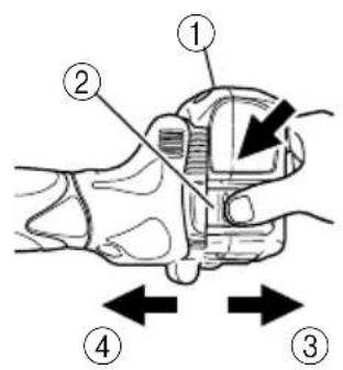
Hold the handle tightly and push the battery latch to remove the battery (See Fig. 1).
CAUTION
Never short-circuit the battery.
2. Battery installation
Insert the battery while observing its polarities (See Fig. 1).
CHARGING
Before using the cordless disc grinder, charge the battery as follows.
- Connect the charger's power cord to a receptacle When the power cord is connected, the charger's pilot lamp will blink in red (At 1-second intervals).
2. Insert the battery into the charger
Insert the battery firmly, until it contacts the bottom of the charger compartment.
CAUTION
○If the battery is inserted in the reverse direction, not only recharging will become impossible, but it may also cause problems in the charger such as deformed recharging terminal.
3. Charging
When inserting a battery in the charger, charging will commence and the pilot lamp will light up continuously in red.
When the battery becomes fully recharged, the pilot lamp will blink in red (At 1-second intervals) (See Table 1).
(1) Pilot lamp indication
The indications of the pilot lamp will be as shown in Table 1, according to the condition of the charger or the rechargeable battery.
Table 1
| Indications of the lamps | |||
| Before charging | Blinks (RED) | Lights for 0.5 seconds. Does not light for 0.5 seconds. (off for 0.5 seconds) | |
| While charging | Lights (RED) | Lights continuously | |
| Charging complete | Blinks (RED) | Lights for 0.5 seconds. Does not light for 0.5 seconds. (off for 0.5 seconds) | |
| Charging impossible | Flickers (RED) | Lights for 0.1 seconds. Does not light for 0.1 seconds. (off for 0.1 seconds)■ ■ ■ ■ ■ ■ ■ ■ ■ ■ ■ ■ ■ ■ ■ ■ ■ ■ ■ ■ ■ ■ ■ ■ ■ ■ ■ ■ ■ ■ ■ ■ ■ ■ ■ ■ ■ ■ ■ ■ ■ ■ ■ ■ ■ ■ ■ ■ ■ ■ ■ ■ ■ ■ ■ ■ ■ ■ ■ ■ ■ ■ ■ ■ ■ ■ ■ ■ ■ ■ ■ ■ ■ ■ ■ ■ ■ ■ ■ ■ ■ ■ ■ ■ ■ ■ ■ ■ ■ ■ ■ ■ ■ ■ ■ ■ ■ ■ ■ ■ ■ □□□□□□□□□□□□□□□□□□□□□□□□□□□□□□□□□□□□□□□□□□□□□□□□□□□□□□□□□□□□□□□□□□□□□□□□□□□□□□□□□□□□□□□□□□□□□□□□□□□□□○□□□□□□□□□□□□□□□□□□□□□□□□□□□□□□□□□□□□□□□□□□□□□□□□□□□□□□□□□□□□□□□□□□□□□□□□□□□□□□□□□□□□□□□□□□□□□□□□□□□ □□□□□□□□□□□□□□□□□□□□□□□□□□□□□□□□□□□□□□□□□□□□□□□□□□□□□□□□□□□□□□□□□□□□□□□□□□□□□□□□□□□□□□□□□□□□□□□□□□ □ □ □ □ □ □ □ □ □ □ □ □ □ □ □ □ □ □ □ □ □ □ □ □ □ □ □ □ □ □ □ □ □ □ □ □ □ □ □ □ □ □ □ □ □ □ □ □ □ □ ▢ ▢ ▢ ▢ ▢ ▢ ▢ ▢ ▢ ▢ ▢ ▢ ▢ ▢ ▢ ▢ ▢ ▢ ▢ ▢ ▢ ▢ ▢ ▢ ▢ ▢ ▢ ▢ ▢ ▢ ▢ ▢ ▢ ▢ ▢ ▢ ▢ ▢ ▢ ▢ ▢ ▢ ▢ ▢ ▢ ▢ ▢ ▢ ▢ ▢ ▩ ▩ ▩ ▩ ▩ ▩ ▩ ▩ ▩ ▩ ▩ ▩ ▩ ▩ ▩ ▩ ▩ ▩ ▩ ▩ ▩ ▩ ▩ ▩ ▩ ▩ ▩ ▩ ▩ ▩ ▩ ▩ ▩ ▩ ▩ ▩ ▩ ▩ ▩ ▩ ▩ ▩ ▩ ▩ ▩ ▩ ▩ ▩ ▩ ▩ ▢ ▢ ▢ ▢ ▢ ▢ ▢ ▢ ▢ ▢ ▢ ▢ ▢ ▢ ▢ ▢ ▢ ▢ ▢ ▢ ▢ ▢ ▢ ▢ ▢ ▢ ▢ ▢ ▢ ▢ ▢ ▢ ▢ ▢ ▢ ▢ ▢ ▢ ▢ ▢ ▢ ▢ ▢ ▢ ▢ ▢ ▢ ▢ ▢ □ □ □ □ □ □ □ □ □ □ □ □ □ □ □ □ □ □ □ □ □ □ □ □ □ □ □ □ □ □ □ □ □ □ □ □ □ □ □ □ □ □ □ □ □ □ □ □ □ △ △ △ △ △ △ △ △ △ △ △ △ △ △ △ △ △ △ △ △ △ △ △ △ △ △ △ △ △ △ △ △ △ △ △ △ △ △ △ △ △ △ △ △ △ △ △ △ △ △ ▲ ▲ ▲ ▲ ▲ ▲ ▲ ▲ ▲ ▲ ▲ ▲ ▲ ▲ ▲ ▲ ▲ ▲ ▲ ▲ ▲ ▲ ▲ ▲ ▲ ▲ ▲ ▲ ▲ ▲ ▲ ▲ ▲ ▲ ▲ ▲ ▲ ▲ ▲ ▲ ▲ ▲ ▲ ▲ ▲ ▲ ▲ ▲ ▲ ▲ △ △ △ △ △ △ △ △ △ △ △ △ △ △ △ △ △ △ △ △ △ △ △ △ △ △ △ △ △ △ △ △ △ △ △ △ △ △ △ △ △ △ △ △ △ △ △ △ △ ▩ △ △ △ △ △ △ △ △ △ △ △ △ △ △ △ △ △ △ △ △ △ △ △ △ △ △ △ △ △ △ △ △ △ △ △ △ △ △ △ △ △ △ △ △ △ △ △ △ △ ▸ ▸ ▸ ▸ ▸ ▸ ▸ ▸ ▸ ▸ ▸ ▸ ▸ ▸ ▸ ▸ ▸ ▸ ▸ ▸ ▸ ▸ ▸ ▸ ▸ ▸ ▸ ▸ ▸ ▸ ▸ ▸ ▸ ▸ ▸ ▸ ▸ ▸ ▸ ▸ ▸ ▸ ▸ ▸ ▸ ▸ ▸ ▸ ▸ ▸ ▪ ▪ ▪ ▪ ▪ ▪ ▪ ▪ ▪ ▪ ▪ ▪ ▪ ▪ ▪ ▪ ▪ ▪ ▪ ▪ ▪ ▪ ▪ ▪ ▪ ▪ ▪ ▪ ▪ ▪ ▪ ▪ ▪ ▪ ▪ ▪ ▪ ▪ ▪ ▪ ▪ ▪ ▪ ▪ ▪ ▪ ▪ ▪ ▪ ▪ ▫ ▫ ▫ ▫ ▫ ▫ ▫ ▫ ▫ ▫ ▫ ▫ ▫ ▫ ▫ ▫ ▫ ▫ ▫ ▫ ▫ ▫ ▫ ▫ ▫ ▫ ▫ ▫ ▫ ▫ ▫ ▫ ▫ ▫ ▫ ▫ ▫ ▫ ▫ ▫ ▫ ▫ ▫ ▫ ▫ ▫ ▫ ▫ ▫ ▫ ▪ ▪ ▪ ▪ ▪ ▪ ▪ ▪ ▪ ▪ ▪ ▪ ▪ ▪ ▪ ▪ ▪ ▪ ▪ ▪ ▪ ▪ ▪ ▪ ▪ ▪ ▪ ▪ ▪ ▪ ▪ ▪ ▪ ▪ ▪ ▪ ▪ ▪ ▪ ▪ ▪ ▪ ▪ ▪ ▪ ▪ ▪ ▪ ▪ ▸ ▸ ▸ ▸ ▸ ▸ ▸ ▸ ▸ ▸ ▸ ▸ ▸ ▸ ▸ ▸ ▸ ▸ ▸ ▸ ▸ ▸ ▸ ▸ ▸ ▸ ▸ ▸ ▸ ▸ ▸ ▸ ▸ ▸ ▸ ▸ ▸ ▸ ▸ ▸ ▸ ▸ ▸ ▸ ▸ ▸ ▸ ▸ ▸ ▩ ▩ ▩ ▩ ▩ ▩ ▩ ▩ ▩ ▩ ▩ ▩ ▩ ▩ ▩ ▩ ▩ ▩ ▩ ▩ ▩ ▩ ▩ ▩ ▩ ▩ ▩ ▩ ▩ ▩ ▩ ▩ ▩ ▩ ▩ ▩ ▩ ▩ ▩ ▩ ▩ ▩ ▩ ▩ ▩ ▩ ▩ ▩ ▩ ▸ ▸ ▸ ▸ ▸ ▸ ▸ ▸ ▸ ▸ ▸ ▸ ▸ ▸ ▸ ▸ ▸ ▸ ▸ ▸ ▸ ▸ ▸ ▸ ▸ ▸ ▸ ▸ ▸ ▸ ▸ ▸ ▸ ▸ ▸ ▸ ▸ ▸ ▸ ▸ ▸ ▸ ▸ ▸ ▸ ▸ ▸ ▸ ▸ ▅ ▪ ▪ ▪ ▪ \textcircled{=} \textcircled{=} \textcircled{=} \textcircled{=} \textcircled{=} \textcircled{=} \textcircled{=} \textcircled{=} \textcircled{=} \textcircled{=} \textcircled{=} \textcircled{=} \textcircled{=} \textcircled{=} \textcircled{=} \textcircled{=} \textcircled{=} \textcircelbrack \textcircled{=} \textcircled{=} \textcircled{=} \textcircled{=} \textcircled{=} \textcircled{=} \textcircled{=} \textcircled{=} \textcircled{=} \textcircled{=} \textcircled{=} \textcircled{=} \textcircled{=} \textcircled{=} \textcircled{=} \textcircled{=} \textcircellbrack \textcircled{=} \textcircled{=} \textcircled{=} \textcircled{=} \textcircled{=} \textcircled{=} \textcircled{=} \textcircled{=} \textcircled{=} \textcircled{=} \textcircled{=} \textcircled{=} \textcircled{=} \textcircled{=} \textcircled{=} \textcircled{=} \mathrm{~B} \mathrm{~B} \mathrm{~B} \mathrm{~B} \mathrm{~B} \mathrm{~B} \mathrm{~B} \mathrm{~B} \mathrm{~B} \mathrm{~B} \mathrm{~B} \mathrm{~B} \mathrm{~B} \mathrm{~B} \mathrm{~B} \mathrm{~B} \mathrm{~B} \mathrm{ ~B} \mathrm{~B} \mathrm{~B} \mathrm{~B} \mathrm{~B} \mathrm{~B} \mathrm{~B} \mathrm{~B} \mathrm{~B} \mathrm{~B} \mathrm{~B} \mathrm{~B} \mathrm{~B} \mathrm{~B} \mathrm{~B} \mathrm{~B} \mathrm{~B} \textcircled{=} \textcircled{=} \textcircled{=} \textcircled{=} \textcircled{=} \textcircled{=} \textcircled{=} \textcircled{=} \textcircled{=} \textcircled{=} \textcircled{=} \textcircled{=} \textcircled{=} \textcircled{=} \textcircled{=} \textcircled{=} \textcirced{=} \textcircled{=} \textcircled{=} \textcircled{=} \textcircled{=} \textcircled{=} \textcircled{=} \textcircled{=} \textcircled{=} \textcircled{=} \textcircled{=} \textcircled{=} \textcircled{=} \textcircled{=} \textcircled{=} \textcircled{=} \textcircled{=} \mathrm{Battery overheated.} \mathrm{Unable to charge} (\mathrm{Charging will commence when battery cools}).\] | |
NOTE: When standby for cooling battery, UC18YRL cools the overheated battery by cooling fan.
(2) Regarding the temperatures of the rechargeable battery
The temperatures for rechargeable batteries are as shown in the table below, and batteries that have become hot should be cooled for a while before being recharged.
Table 2 Recharging ranges of batteries
| Rechargeable batteries\Charger | UC14YFAUC24YFA | UC18YRL |
| Ni-Cd batteries -5°C - | 55°C | |
| Ni-MH batteries 0°C - | 45°C -5°C - 50°C | |
| Li-ion batteries x 0°C - | 50°C | |
-
Disconnect the charger's power cord from the receptacle
-
Hold the charger firmly and pull out the battery NOTE
Be sure to pull out the battery from the charger after use, and then keep it.
CAUTION
☐If the battery is charged while it is heated because it has been left for a long time in a location subject to direct sunlight or because the battery has just been used, the pilot lamp of the charger lights up green. In such a case, first let the battery cool, then start charging.
When the pilot lamp flickers in red quickly (at 0.2-second intervals), check for and take out any foreign objects in the charger's battery installation hole. If there are no foreign objects, it is probable that the battery or charger is malfunctioning. Take it to your Authorized Service Center.
○Since the built-in micro computer takes about 3 seconds to confirm that the battery being charged with UC14YFA, UC24YFA and UC18YRL are taken out, wait for a minimum of 3 seconds before reinserting it to continue charging. If the battery is reinserted within 3 seconds, the battery may not be properly charged.
Before using the cordless disc grinder, charge the battery as follows.
- Connect the charger power cord to the receptacle
Connecting the power cord will turn on the charger.
- Insert the battery into the charger
Insert the battery firmly while observing its direction, until it contacts the bottom of the charger (the pilot lamp lights up).
CAUTION
If the pilot lamp does not light up, pull out the power cord from the receptacle and check the battery mounting condition.
The pilot lamp goes off to indicate that the battery is fully charged.
The battery charging time becomes longer when a temperature is low or the voltage of the power source is too low.
When the pilot lamp does not go off even if more than 120 minutes have elapsed after starting of the charging, stop the charging and contact your HiKOKI AUTHORIZED SERVICE CENTER.
CAUTION
If the battery is heated due to direct sunlight, etc., just after operation, the charger pilot lamp may not light up. At that time, cool the battery first, then start charging.
-
Disconnect the charger power cord from the receptacle
-
Hold the charger tight and pull out the battery
Regarding electric discharge in case of new batteries, etc.
As the internal chemical substance of new batteries and batteries that have not been used for an extended period is not activated, the electric discharge might be low when using them the first and second time. This is a temporary phenomenon, and normal time required for recharging will be restored by recharging the batteries 2 – 3 times.
How to make the batteries perform longer
(1) Recharge the batteries before they become completely exhausted.
When you feel that the power of the tool becomes weaker, stop using the tool and recharge its battery. If you continue to use the tool and exhaust the electric current, the battery may be damaged and its life will become shorter.
(2) Avoid recharging at high temperatures.
A rechargeable battery will be hot immediately after use. If such a battery is recharged immediately after use, its internal chemical substance will deteriorate, and the battery life will be shortened. Leave the battery and recharge it after it has cooled for a while.
PRIOR TO OPERATION
- Preparing and checking the work environment
Make sure that the work site meets all the conditions laid forth in the precautions.
- Checking the battery
Make sure that the battery is installed firmly. If it is at all loose it could come off and cause an accident.
- Fitting and adjusting the wheel guard
The wheel guard is a protective device to prevent injury should the depressed center wheel shatter during operation. Ensure that the guard is properly fitted and fastened before commencing grinding operation. By slightly loosening the setting screw, the wheel guard can be turned and set at any desired angle for maximum operational effectiveness. Ensure that the setting screw is thoroughly tightened after adjusting the wheel guard.
- Ensure that mounted wheels and points are fitted in accordance with the manufacturer's instructions. Ensure that the depressed center wheel to be utilized is the correct type and free of cracks or surface defects. Also ensure that the depressed center wheel is properly mounted and the wheel nut is securely tightened, Refer to the section on "ASSEMBLING AND DISASSEMBLING THE DEPRESSED CENTER WHEEL"
Ensure that blotters are used when they are provided with the bonded abrasive product and when they are required.
Do not use separate reducing bushings or adaptors to adapt large hole abrasive wheels.
For tools intended to be fitted with threaded hole wheel, ensure that the thread in the wheel is long enough to accept the spindle length.
Do not use cutting off wheel for side grinding.
- Conducting a trial run
Ensure that the abrasive products is correctly mounted and tightened before use and run the tool at no-load for 30 seconds in a safe position, stop immediately if there is considerable vibration or if other defects are detected.
If this condition occurs, check the machine to determine the cause.
- Confirm the push button.
Confirm that the push button is disengaged by pushing push button two or three times before switching the power tool on (See Fig. 2).
- Fixing the side handle.
Screw the side handle into the gear cover.
PRACTICAL GRINDER APPLICATION
- Pressure
To prolong the life of the machine and ensure a first class finish, it is important that the machine should not be overloaded by applying too much pressure. In most applications, the weight of the machine alone is sufficient for effective grinding. Too much pressure will result in reduced rotational speed, inferior surface finish, and overloading which could reduce the life of the machine.
- Grinding angle
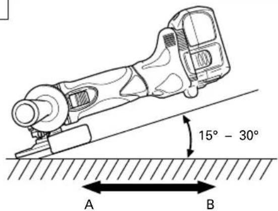
Do not apply the entire surface of the depressed center wheel to the material to be ground. As shown in Fig. 1, the machine should be held at an angle of 15^-30^ so that the external edge of the depressed center wheel contacts the material at an optimum angle.
- To prevent a new depressed center wheel from digging into the workpiece, initial grinding should be performed by drawing the grinder across the workpiece toward the operator (Fig. 1 direction B).
Once the leading edge of the depressed center wheel is properly abraded, grinding may be conducted in either direction.
4. Precautions immediately after finishing operation
The wheel continues to rotate after the tool is switched off.
After switching off the machine, do not put it down until the depressed center wheel has come to a complete stop. Apart from avoiding serious accidents, this precaution will reduce the amount of dust and swarf sucked into the machine.
NOTE
To prevent injuries, this product has a function that prevents unexpected motor rotation when the battery is inserted. The motor will not run if the battery is inserter while the switch is still ON. After installing the battery, turn the switch off and then back on again.
The G14DL and G18DL models are equipped with a protection function that will shut down the tool in the event of an overload.
Should the tool shut down due to an overload, turn the power off and then turn it back on again.
An overload that stops tool operation and lasts more than 10 seconds may not be released by turning the power off and on. Should this happen, remove the battery from the tool and reinstall it before turning on the power switch.
CAUTIONS
○Check that the work piece is properly supported.
○Ensure that ventilation openings are kept clear when working in dusty conditions.
If it should become necessary to clear dust, first disconnect the tool from the mains supply (use non-metallic objects) and avoid damaging internal parts.
○Ensure that sparks resulting from use do not create a hazard e.g. do not hit persons, or ignite flammable substances.
○Always use eye and ear protection.
Other personal protective equipment such as dust mask, gloves, helmet and apron should be worn when necessary.
If in doubt, wear the protective equipment.
○When the machine is not use, the battery should be disconnected.
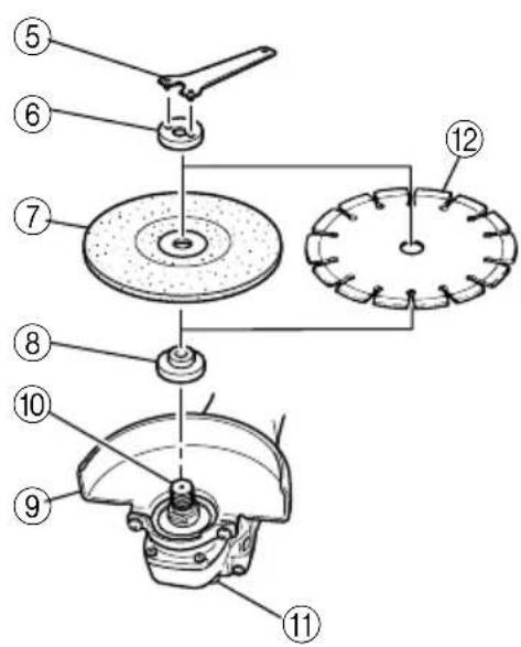
ASSEMBLING AND DISASSEMBLING THE DEPRESSED CENTER WHEEL (Fig. 2)
CAUTION: Be sure to turn off the switch and pull out the battery.
1. Assembling (Fig. 2)
(1) Turn the disc grinder upsidedown so that the spindle is facing upward.
(2) Align the across flats of the wheel washer with the notched part of the spindle, then attach them.
(3) Fit the protuberance of the depressed center wheel onto the wheel washer.
(4) Screw the wheel nut onto the spindle.
(5) While pushing the push button with one hand, lock the spindle by turning the depressed center wheel slowly with the other hand.
Tighten the wheel nut by using the supplied wrench as shown in Fig. 2.
2. Disassembling
Follow the above procedures in reverse.
CAUTIONS
○Confirm that the depressed center wheel is mounted firmly.
○Confirm that the push button is disengaged by pushing push button two or three times before switching the power tool on.
MAINTENANCE AND INSPECTION
1. Inspecting the depressed center wheel
Ensure that the depressed center wheel is free of cracks and surface defects.
2. Inspecting the mounting screws
Regularly inspect all mounting screws and ensure that they are properly tightened. Should any of the screws be loose, retighten them immediately. Failure to do so could result in serious hazard.
3. Maintenance of the motor
The motor unit winding is the very "heart" of the power tool.
Exercise due care to ensure the winding does not become damaged and/or wet with oil or water.
4. Inspecting the carbon brushes (Fig. 4)
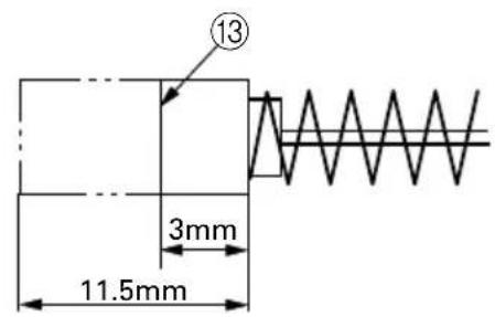
The motor employs carbon brushes which are consumable parts. Since and excessively worn carbon brush can result in motor trouble, replace the carbon brush with new ones when it becomes worn to or near the “wear limit”. In addition, always keep carbon brushes clean and ensure that they slide freely within the brush holders.
NOTE
When replacing the carbon brush with a new one, be sure to use the HiKOKI Carbon Brush Code No. 999054.
5. Replacing carbon brushes
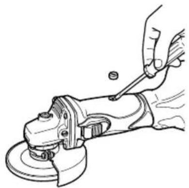
Take out the carbon brush by first removing the brush cap and then hooking the protrusion of the carbon brush with a slotted head screw driver, etc., as shown in Fig. 6.
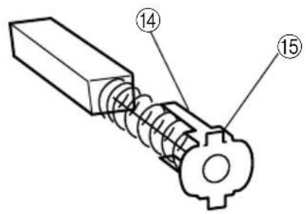
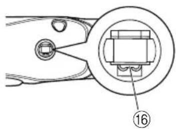
When installing the carbon brush, choose the direction so that the nail of the carbon brush agrees with the contact portion outside the brush tube. Then push it in with a finger as illustrated in Fig. 7. Lastly, install the brush cap.
CAUTION
Be absolutely sure to insert the nail of the carbon brush into the contact portion outside the brush tube. (You can insert whichever one of the two nails provided.)
Caution must be exercised since any error in this operation can result in the deformed nail of the carbon brush and may cause motor trouble at an early stage.
6 Cleaning of the outside
When the cordless disc grinder is stained, wipe with a soft dry cloth or a cloth moistened with soapy water. Do not use chloric solvents, gasoline or paint thinner, as they melt plastics.
7. Storage
Store the cordless disc grinder in a place in which the temperature is less than 40^ C, and out of reach of children.
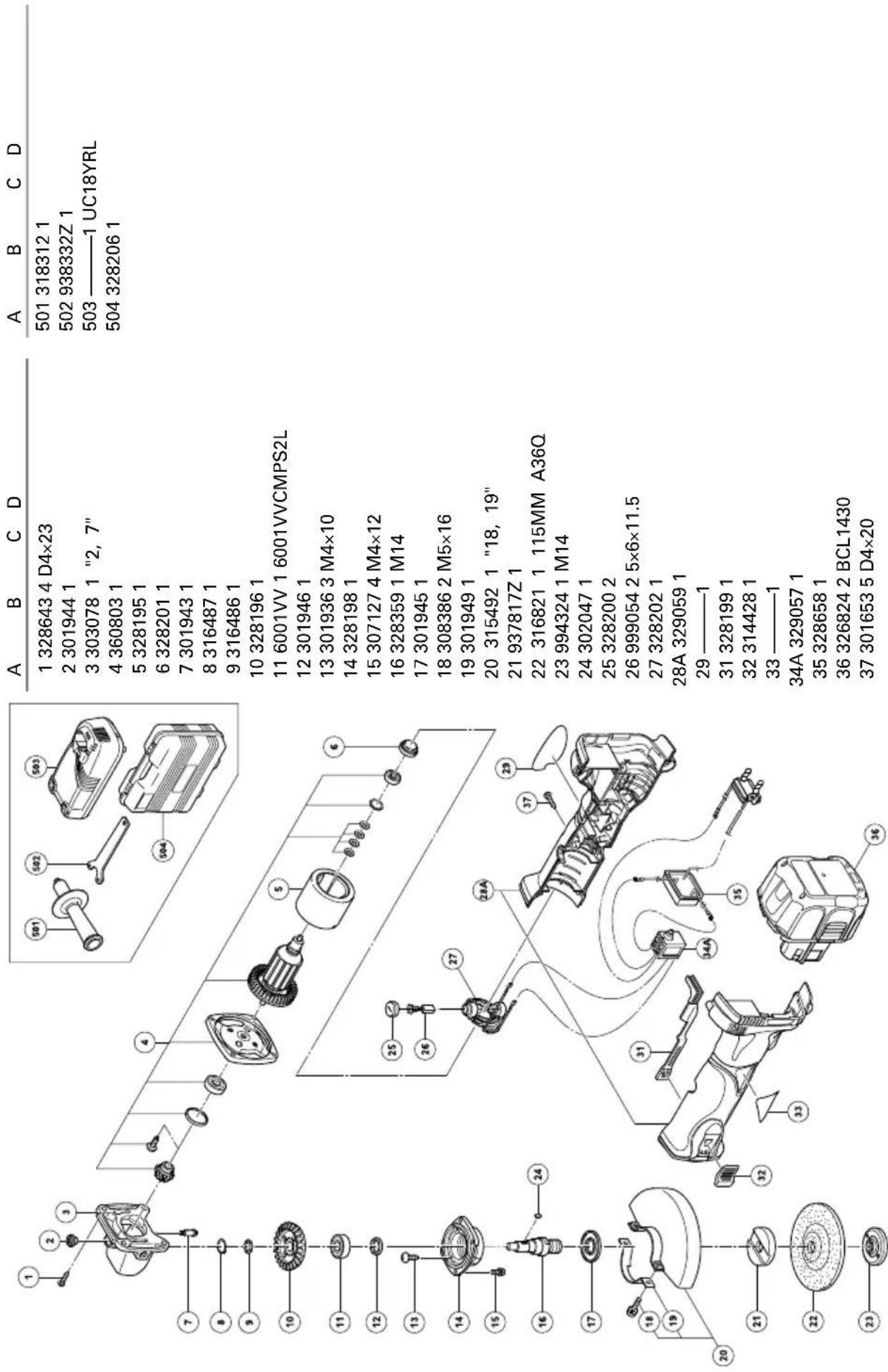
8. Service parts list
A: Item No.
B: Code No.
C: No. Used
D: Remarks
CAUTION
Repair, modification and inspection of HiKOKI Power Tools must be carried out by a HiKOKI Authorized Service Center.
This Parts List will be helpful if presented with the tool to the HiKOKI Authorized Service Center when requesting repair or other maintenance.
In the operation and maintenance of power tools, the safety regulations and standards prescribed in each country must be observed.
MODIFICATIONS:
HiKOKI Power Tools are constantly being improved and modified to incorporate the latest technological advancements.
Accordingly, some parts (i.e. code numbers and/or design) may be changed without prior notice.
NOTE
Due to HiKOKI's continuing program of research and development, the specifications herein are subject to change without prior notice.
Information concerning airborne noise and vibration
The measured values were determined according to EN60745 and declared in accordance with ISO 4871.
Measured A-weighted sound power level: 85 dB (A) Measured A-weighted sound pressure level: 74 dB (A) Uncertainty KpA: 3 dB (A).
Wear ear protection.
Vibration total values (triax vector sum) determined according to EN60745.
Surface grinding:
Vibration emission value h , AG = 9.3 m/s^2
Uncertainty K = 1.5 m/s ^4
The declared vibration total value has been measured in accordance with a standard test method and may be used for comparing one tool with another.
It may also be used in a preliminary assessment of exposure.
WARNING
○The vibration emission during actual use of the power tool can differ from the declared total value depending on the ways in which the tool is used.
○Identify safety measures to protect the operator that are based on an estimation of exposure in the actual conditions of use (taking account of all parts of the operating cycle such as the times when the tool is switched off and when it is running idle in addition to the trigger time).
G14DMR
| A | B | C | D | |
| 1 328643 4 D4×23 | ||||
| 2 301944 1 | ||||
| 3 303078 1 "2, 7" | ||||
| 4 360803 1 | ||||
| 5 328195 1 | ||||
| 6 328201 1 | ||||
| 7 301943 1 | ||||
| 8 316487 1 | ||||
| 9 316486 1 | ||||
| 10 328196 1 | ||||
| 11 6001VV 1 6001VVCMPS2L | ||||
| 12 301946 1 | ||||
| 13 301936 3 M4×10 | ||||
| 14 328198 1 | ||||
| 15 307127 4 M4×12 | ||||
| 16 328359 1 M14 | ||||
| 17 301945 1 | ||||
| 18 308386 2 M5×16 | ||||
| 19 301949 1 | ||||
| 20 315492 1 "18, 19" | ||||
| 21 937817Z 1 | ||||
| 22 316821 1 115MM A36Q | ||||
| 23 994324 1 M14 | ||||
| 24 302047 1 | ||||
| 25 328200 2 | ||||
| 26 999054 2 5×6×11.5 | ||||
| 27 328202 1 | ||||
| 28A 329059 1 | ||||
| 29——1 | ||||
| 31 328199 1 | ||||
| 32 314428 1 | ||||
| 33——1 | ||||
| 34A 329057 1 | ||||
| 35 328658 1 | ||||
| 36 315130 2 EB14B | ||||
| 37 301653 5 D4×20 | ||||
G14DL
G18DMR
| A | B | C | D | |
| 1 328643 4 D4×23 | ||||
| 2 301944 1 | ||||
| 3 303078 1 "2, 7" | ||||
| 4 360804 1 | ||||
| 5 328195 1 | ||||
| 6 328201 1 | ||||
| 7 301943 1 | ||||
| 8 316487 1 | ||||
| 9 316486 1 | ||||
| 10 328364 1 | ||||
| 11 6001VV 1 6001VVCMPS2L | ||||
| 12 301946 1 | ||||
| 13 301936 3 M4×10 | ||||
| 14 328198 1 | ||||
| 15 307127 4 M4×12 | ||||
| 16 328359 1 M14 | ||||
| 17 301945 1 | ||||
| 18 308386 2 M5×16 | ||||
| 19 301949 1 | ||||
| 20 315492 1 "18, 19" | ||||
| 21 937817Z 1 | ||||
| 22 316821 1 115MM A36Q | ||||
| 23 994324 1 M14 | ||||
| 24 302047 1 | ||||
| 25 328200 2 | ||||
| 26 999054 2 5×6×11.5 | ||||
| 27 328202 1 | ||||
| 28A 329060 1 | ||||
| 29——1 | ||||
| 31 328199 1 | ||||
| 32 314428 1 | ||||
| 33——1 | ||||
| 34A 329057 1 | ||||
| 35 328658 1 | ||||
| 36 322880 2 EB1820L | ||||
| 37 301653 5 D4×20 | ||||
G18DL
| A | B | C | D | |
| 1 | 328643 | 4 | D4×23 | |
| 2 | 301944 | 1 | ||
| 3 | 303078 | 1 | "2, 7" | |
| 4 | 360804 | 1 | ||
| 5 | 328195 | 1 | ||
| 6 | 328201 | 1 | ||
| 7 | 301943 | 1 | ||
| 8 | 316487 | 1 | ||
| 9 | 316486 | 1 | ||
| 10 | 328364 | 1 | ||
| 11 | 6001VV | 1 | 6001VVCMPS2L | |
| 12 | 301946 | 1 | ||
| 13 | 301936 | 3 | M4×10 | |
| 14 | 328198 | 1 | ||
| 15 | 307127 | 4 | M4×12 | |
| 16 | 328359 | 1 | M14 | |
| 17 | 301945 | 1 | ||
| 18 | 308386 | 2 | M5×16 | |
| 19 | 301949 | 1 | ||
| 20 | 315492 | 1 | "18, 19" | |
| 21 | 937817Z | 1 | ||
| 22 | 316821 | 1 | 115MM A36Q | |
| 23 | 994324 | 1 | M14 | |
| 24 | 302047 | 1 | ||
| 25 | 328200 | 2 | ||
| 26 | 999054 | 2 | 5×6×11.5 | |
| 27 | 328202 | 1 | ||
| 28A | 329060 | 1 | ||
| 29 —— | 1 | |||
| 31 | 328199 | 1 | ||
| 32 | 314428 | 1 | ||
| 33 —— | 1 | |||
| 34A | 329057 | 1 | ||
| 35 | 328658 | 1 | ||
| 36 | 326240 | 2 | EBM1830 | |
| 37 | 301653 | 5 | D4×20 |
Hikoki Power Tools Norway AS
Kjeller Vest 7, N-2007 Kjeller, Norway
Tel: (+47) 6692 6600
Fax: (+47) 6692 6650
URL: http://www.hikoki-powertools.no
Hikoki Power Tools Sweden AB
Rotebergsvagen 2B SE-192 78 Sollentuna, Sweden
Tel: (+46) 8 598 999 00
Fax: (+46) 8 598 999 40
URL: http://www.hikoki-powertools.se
Hikoki Power Tools Denmark A/S
Lillebaeltsvej 90, 6715 Esbjerg N, Denmark
Tel: (+45) 75 14 32 00
Fax: (+45) 75 14 36 66
URL: http://www.hikoki-powertools.dk
Hikoki Power Tools Finland Oy
Tupalankatu 9, 15680 Lahti, Finland
Tel: (+358) 20 7431 530
Fax: (+358) 20 7431 531
URL: http://www.hikoki-powertools.fi
natural_image
Line drawing of a quill pen with inkwell (no text or symbols)| Svenska Suomi | ||
| EG-DEKLARATION BETRÄFFANDE LIKFORMIGHETViförklarar på eget ansvar att denna batteridrivna vinkelslip, identifierad enligt typ och särskild identifikationskod *1), överensstämmer med alla relevanta krav i direktiven *2) och standarderna *3). Teknisk fil enligt *4) – Se nedan.Den europeiska standardansvariga på representationskontoret i Europa är auktoriserad att sammanställa den tekniska fi len.Denna försåkran gäller för produkten med tillhörande CE-märkning. | EY-ILMOITUS YHDENMUKAISUUDESTAVakuutamme yksinomaisella vastuullamme, että akkutoiminen kulmahiomakone, joka identifi oidaan tyypin ja erityis tunnistuskoodin *1) perusteella, on kaikkien direktiivien *2) ja standardien *3) asiaankuuluvien vaatimusten mukainen. Tekninen tiedosto kohdassa *4) – katso alta.Eurooppalaisten standardien hallintaelin Euroopan edustustossa on valtuutettu kokoamaan teknisen tiedoston.Ilmoitus on sovellettavissa tuotteeseen kiinnitettyyn CE-merkintään. | |
| Dansk English | ||
| EF-OVERENSSTEMMELSESERKLÆRINGVi erklærer os fuldstændig ansvarlige for, at batteri vinkelsliber, identificeret ved type og specifik identifikationskode *1), er i overensstemmelse med alle relevante krav i direktiverne *2) og standarderne *3). Teknisk fi i *4) – Se nedenfor.Lederen af europæiske standarder på repräsentationskontoret i Europa er bemyndiget til at kompilere den tekniske fi I.Erklæringen gælder produktet, der er mærket med CE. | EC DECLARATION OF CONFORMITYWe declare under our sole responsibility that Cordless Disc Grinder, identified by type and specific identification code *1), is in conformity with all relevant requirements of the directives *2) and standards *3). Technical fi le at *4) – See below.The European Standard Manager at the representative office in Europe is authorized to compile the technical fi le.The declaration is applicable to the product affi xed CE marking. | |
| Norsk | ||
| EF'S ERKLÆRING OM OVERENSSTEMMELSEVi erklærer på eget ansvar at batteridrevet vinkelsliper, identifisert etter type og spesifikk identifikasjonskode *1), er i samsvar med alle relevante krav i direktiver *2) og standarder *3). Teknisk fil under *4) - Se nedenfor.Styreren for europeiske standarder ved representantkontoret i Europa er autorisert til å kompilere den tekniske fi len.Erklæringen gjelder for CE-merket på produktet. | ||
| *1) G18DL C344668RG14DL C344667R*2) 2006/42/EC, 2014/30/EU, 2014/35/EU, 2011/65/EU*3) EN60745-1:2009+A11:2010EN60745-2-3:2011+A2:2013+A11:2014+A12:2014+A13:2015EN60335-1:2012+A11:2014EN60335-2-29:2004+A2:2010EN55014-1:2006+A1:2009+A2:2011EN55014-2:1997+A1:2001+A2:2008 | ||
| *4) Representative offi ce in EuropeHikoki Power Tools Deutschland GmbHSiemensring 34, 47877 Willich, GermanyHead offi ce in JapanKoki Holdings Co., Ltd.Shinagawa Intercity Tower A, 15-1, Konan 2-chome, Minato-ku, Tokyo, Japan | 29. 6. 2018Naoto YamashiroEuropean Standard Manager29. 6. 2018A. NakagawaCorporate Offi cer | |
Koki Holdings Co., Ltd.
- Batteridriven vinkelslip Batteri vinkelsliber Batteridrevet vinkelsliper Akkutoiminen kulmahiomakone Cordless Disc Grinder
- G 14DMR • G 14DL G 18DMR • G 18DL
- VEDLIKEHOLD OG INSPEKSJON
- Save all warnings and instructions for future reference.
- 1) Work area safety
- 2) Electrical safety
- 3) Personal safety
- 4) Power tool use and care
- PRECAUTION
- SAFETY WARNINGS COMMON FOR GRINDING OR ABRASIVE CUTTING-OFF OPERATIONS
- KICKBACK AND RELATED WARNINGS
- SAFETY WARNINGS SPECIFIC FOR GRINDING AND ABRASIVE CUTTING-OFF OPERATIONS
- ADDITIONAL SAFETY WARNINGS SPECIFIC FOR ABRASIVE CUTTING-OFF OPERATIONS
- GENERAL SAFETY INSTRUCTIONS FOR CORDLESS DISC GRINDERS
- CAUTION ON LITHIUM-ION BATTERY
- WARNING
- CAUTION
- SPECIFICATIONS
- APPLICATIONS
- BATTERY REMOVAL/INSTALLATION
- Battery removal
- Battery installation
- CHARGING
- Insert the battery into the charger
- Charging
- How to make the batteries perform longer
- PRIOR TO OPERATION
- PRACTICAL GRINDER APPLICATION
- Precautions immediately after finishing operation
- NOTE
- CAUTIONS
- ASSEMBLING AND DISASSEMBLING THE DEPRESSED CENTER WHEEL (Fig. 2)
- Assembling (Fig. 2)
- Disassembling
- MAINTENANCE AND INSPECTION
- Inspecting the depressed center wheel
- Inspecting the mounting screws
- Maintenance of the motor
- Inspecting the carbon brushes (Fig. 4)
- Replacing carbon brushes
- Cleaning of the outside
- Storage
- Service parts list
- MODIFICATIONS:
- Information concerning airborne noise and vibration
- Hikoki Power Tools Norway AS
- Hikoki Power Tools Sweden AB
- Hikoki Power Tools Denmark A/S
- Hikoki Power Tools Finland Oy
- Koki Holdings Co., Ltd.
Brand : HiKOKI
Model : G 14DMR
Category : Grinder