BGM1001 - Orbital sander Ferm - Free user manual and instructions
Find the device manual for free BGM1001 Ferm in PDF.


| Type de produit | Belt and disc sander |
| Modèle | BGM1001 |
| Marque | Ferm |
| Pression acoustique | 71 dB(A) |
| Dimensions de la bande | 100 x 915 mm |
| Diamètre du disque | 150 mm |
| Grain du papier abrasif | P60 (grossier), P100 (moyen), P150 (fin) |
| Matériau du châssis | Fonte et acier |
| Fonctions | Ponçage à bande et à disque, réglage vertical de la bande, table inclinable, guide à onglet |
| Sécurité | Lunettes de sécurité, masque anti-poussière, éviter les rallonges longues, maintenir le câble éloigné |
| Entretien | Nettoyer les fentes de ventilation, pas de lubrification nécessaire |
| Pièces détachées | Disponibles, références dans la notice (ex. roulement 6201ZZ, galet, etc.) |
| Réparabilité | Vue éclatée et liste de pièces fournies |
| Accessoires inclus | Bande abrasive, disque abrasif, guide, table, équerre à onglet |
Frequently Asked Questions - BGM1001 Ferm
User questions about BGM1001 Ferm
0 question about this device. Answer the ones you know or ask your own.
Ask a new question about this device
Download the instructions for your Orbital sander in PDF format for free! Find your manual BGM1001 - Ferm and take your electronic device back in hand. On this page are published all the documents necessary for the use of your device. BGM1001 by Ferm.
USER MANUAL BGM1001 Ferm
Product: Ferm Beltsander
Type BS-702, Article number 330702
Ferm, Genemuiden, The Netherlands
Sound pressure level L_pa
71 dB(A)
SERIAL NUMBER
The serial number on the machine consists of the following elements.
Serial nr.
ORDER NUMBER/YEAR OF CONSTRUCTION
READ THIS MANUAL CAREFULLY BEFORE USING THE BELTSANDER!
I. SPECIFIC SAFETY RULES
BEFORE USING THE MACHINE:
- The following points need to be checked:
- Do the connecting voltage of the machine correspond with the mains voltage;
- Are the mains lead and the mains plug in a good condition; strong, without travels or damages.
- For functional reasons the turning parts of this machine are not covered. Therefore it is of utmost importance to be careful. Hold the workpiece firmly, to prevent it from slipping from your hands. Never touch the sanding surfaces of a working machine with your hands.
- Avoid the use of long extension cables.
- If necessary, secure the sanding machine with screws.
- Always keep the mains cable away from moving parts of the machine;
- Usesafetygoggles;
- Use a dust mask.
-
defective mains plug, mains line or damage to the mains line;
-
defective switch:
- smoke or bad smell caused by scorched isolation.
2. INSTALLATION
Avoid the use of long extension cables. If necessary, secure the sanding machine on a working bench with help of screws through the holes in the feet of the machine frame. Do not forget to leave enough space around the machine for the workpieces to be sanded.
3. DESCRIPTION
This machine combines all the advantages of a horizontal and a vertical belt sander with chose of a disc sander. Its sturdy construction in cast iron and steel makes the machine suitable for every sanding job.
4. BEFORE PUTTING THE MACHINE INTO OPERATION
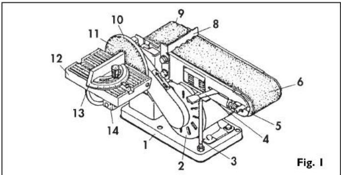
- Machine frame;
- Motor:
- Roller stop and parallel stop:
- Clamping handles:
- Transportroller:
- Sanding belt:
- Fence:
- Drive roller:
- Aluminium disc
- Sanding disc;
- Work plate:
- Mitrescale:
- Supporting arm.
ASSEMBLY
- Put the machine frame on its head and press the four rubber stops into the foot of the frame.
- Machine frame, aluminium disc (10) and work plate (12) are supplied in separate packaging.
- Push the aluminium disc on the shaft and fasten the
AVAILABLE SPARE PARTS FOR BS-702
| REF.NR.DESCRIPTION FERM NR. | ||
| 4 BALL BEARING 6201 ZZ 806201 | ||
| 5 DRIVE ROLLER 402800 | ||
| 12 ADJUSTMENT BOLT 402801 | ||
| 14 IDLER ROLLER 402802 | ||
| 17 PLATE TABLE 402803 | ||
| 21 DRIVE PULLEY 402804 | ||
| 23 MOTOR 402805 | ||
| 27 BASE PLATE 402806 | ||
| 28 SWITCH 402807 | ||
| 30 BAR | 402809 | |
| 31 ADJUSTMENT BLOCK | 402810 | |
| 32MOTOR PULLEY | 402811 | |
| 33V-BELT M21 | 402812 | |
| 36 ALUMINIUM DISC | 402815 | |
| 39 TABLE BRACKET | 402816 | |
| 40 TABLE TILT TRUNION | 402817 | |
| 41 MITRE BAR | 402818 | |
| 42 KNOB/BOLT FOR MITRE BAR | 402819 | |
| 46 TABLE | 402820 | |
| 47 MITRE GAUGE 402821 | ||
| 49 SHAFT FOR DRIVE ROLLER | 402822 | |
| 51 SHAFT FOR IDLER ROLLER | 402823 | |
| 52 BALL BEARING 6201 ZZ 806201 | ||
| 56 INDICATOR | 402824 | |
| 78 CAPACITOR (6 μF=450 VAC) | 402825 | |
| 77 | RUBBER FOOT 402826 | |
EXPLODED VIEW

disc with the socket bolt in the side of the disc.
- Place the work plate (12) with the shaft in the machine frame and secure the work plate with the bolt in the side of the machine frame. Check with a 90° sash angle on the work plate and against the sanding disc if the angle is exactly 90°.
- If necessary, adjust this angle with the calibration indicator.
- The mitre scale (13), which is also supplied separately, can be placed on the work plate (13). With the use of this mitre scale the angle of grinding can be determined precisely.
- The fence (8) for the belt sander can be placed behind the uppermost bolt of the V-belt guard. In this way the workpiece can be held firmly against the belt, without great hazards.

To prevent the workpiece or your fingers from getting caught between the work plate (12) and the sanding disc (11), the space between work plate (12) and sanding disc (11) must not exceed 1.6 mm.
THE CHOICE OF SANDING PAPER
With coarse sanding paper (P 60) generally most of the material can be removed, and fine sanding paper (P 150) is then used for finishing. An uneven surface is first treated with coarse sanding paper and sanded until it is even. Subsequently medium-coarse sanding paper (P 100) is used to remove the scratches caused by the first type of paper used. Fine sanding paper (P 150) is used for finishing. The sanding needs to be continued until the surface is smooth.
THE PLACING OF THE SANDING PAPER (SEE FIG. 2)
When the sanding machine is held with the sanding disc turned towards you, the sanding belt moves from right to left along the upper part of the machine. Because of this turning direction the workpiece will be pressed against the right side of the fence. An arrow on the inside indicates the right direction of running of the sanding belt (see drawing). If no direction is indicated, the sanding belt must be placed in such a way that the elevated part of the seam is placed into the turning direction of the belt. So it is very important that the sanding belt is placed in the correct way. The machine uses standard 100 x 915 mm sanding belts (nr 7):
- Remove the plug from the mains socket;
- Push the clamping handle completely to the right
to take away the tension of the transport rollers; - Push the sanding belt along both of the transport.
- Push the clamping handle completely to the left
- Push the clamping handle completely to the here. Now the sanding belt should be completely right.
- Turn the transport roller exactly in a right angle to
the direction of the sanding belts with the use of the winged nut at the right roller. The direction of
running of the belt is adjusted correctly if the sides of the sanding belt are running parallel to the bearing plate.
THESANDINGDISC
Paper or "velcro" plates are used for the sanding disc. The standard diameter is 150 mm. The plates are self adhesive.
VERTICAL PLACING OF THE SANDING BELT (SEE FIG. 4)
For more flexibility of the sanding belt its bottom side can be used, because there is no bearing plate. For an easy reach of this bottom side the sanding belt can be placed in vertical position:
- Loosen the two nuts (1) at the front of the sanding machine, around the left transport roller shaft, with the use of an open-end spanner;
- Push the sanding belt up in the position desired;
- Fasten the two nuts (1) again;
- The workpiece can now rest on the worktop instead of on the sanding belt;
- The work plate which is used for the sanding disc can now be pushed with the shaft into the hole of the machine frame, at the left side of the sanding machine;
- Fasten the bolt at the back of the machine;
- The work plate can now be used as support for the sanding of the work piece against the sanding belt.
- Press the switch into position 'I' to put your sanding machine into operation.
- To switch off the machine the same switch needs to be pressed to position '0'.
- Always keep the mains cable away from moving parts.
- There is no need to apply any pressure with the workpiece, because this only slows down the speed of the sanding disc.
The sanding belt and disc supplied with this sanding machine are suitable for the sanding of metal, wood or synthetic surfaces. The workpiece should always be held firmly during sanding. No extra pressure is needed. Guide the work piece up and down over the sanding belt, in order to prevent the sanding belt and plate from wearing through in one place. Round objects can be sanded at the ends of the sanding belt (see Fig. 3). Work pieces which are longer than the sanding machine can be sanded by removing the fence.
NB: To prevent splintering, wood always needs to be sanded in the longitudinal direction of the grain.
To treat a very soft surface, there is a very handy method to 'bring the particles to the surface'. This is done as follows: wet the already sanded surface with a cloth or sponge and let it dry well. Some wood fibres will swell up more than others, which leads to a rougher surface than before. Now the higher particles are treated with fine sanding paper, the results a remarkably smooth surface. This method should not be applied with varnish wood, however, because the varnish may come loose because of the moisture.
7. MAINTENANCE

While maintaining and cleaning the machine pull the plug from the mainssocket. Never use water or other agressive liquids to clean the machine. Clean the machine by brushing it with a brush.
PERIODIC MAINTANCE OF THE BELT SANDER WILL PREVENT UNNECESSARY PROBLEMS!
I. Keep the ventilation slots of the machine clean to prevent overheating of the motor.
- There is no need to lubricate the transport rollers of the machine.
8. MALFUNCTION
Below we have listed a number of possible causes and corresponding solutions in case the machine does not function as it should:
I. The electromotor getshot.
The cool ventilation slots in the motor are stopped up with dirt:
- clean the cool ventilation slots.
The motor is defective:
- Have your sanding machine repaired or checked at your local Ferm dealer.
2. The connected machine does not work.
Interruption in the mains connection
- Check mains connection for fracture;
- Have your sounding machine repaired! checked at your local Ferm dealer.
C DECLARATION OF CONFORMITY (GB)
We declare under our sole responsibility that this product is in conformity with the following standards or standardized documents
EN61029-1
EN55014, EN61000-3-2, EN61000-3-3, EN55104
in accordance with the regulations:
89/392/EEC
73/23/EEC
89/336/EEC
from 01-03-2003
GENEMUIDEN NL
W. Kamphof
Quality department


natural_image
Simple line drawing of a cylindrical object with directional arrows indicating flow or movement (no text or symbols)
natural_image
Technical line drawing of a mechanical device with labeled components, no readable text or symbols present
natural_image
Technical line drawing of a mechanical component labeled Fig. 3 (no text or symbols on the diagram itself)ÉCLARATION DE CONFORMITÉ (F)
CERKLÆRING AV ANSVARSFORHOLD (N)
fra 01-03-2003 GENEMUIDEN NL W. Kamphof Quality department

DK Dansk
a partir de 01-03-2003 GENEMUIDEN NL W. Kamphof Quality department

TILBEH∅R (SEFIGUR I)
-
Chassis
-
Motor
-
Førings- og parallelstiller
-
Spennhändtak
-
Føringsrulle
-
Slipebând
-
Sidestiller
-
Drivrulle
-
Aluminiumskive
-
Slipeskive
-
Arbeidsbord
-
Gradskala
-
Bærearm
MONTERING
4. INNAN MASKINEN TAS I DRIFT
DRIFT(SEFIG.1)
-
Maskinram;
-
Motor;
-
Styr- och parallell-änhallsplatta;
-
Spännhandtag
-
Spyrulle:
-
Stryn, 6. Sliphonds
-
Slipboard;
-
Langdstod
-
DVMFulie
-
Aluminiumskiva;
-
Slipskiva;
-
Arbetsblad:
-
Gerinelåda:
-
Bärarm.
MONTERING
- SERIAL NUMBER
- ORDER NUMBER/YEAR OF CONSTRUCTION
- SPECIFIC SAFETY RULES
- BEFORE USING THE MACHINE:
- INSTALLATION
- DESCRIPTION
- BEFORE PUTTING THE MACHINE INTO OPERATION
- ASSEMBLY
- THE CHOICE OF SANDING PAPER
- THE PLACING OF THE SANDING PAPER (SEE FIG. 2)
- THESANDINGDISC
- VERTICAL PLACING OF THE SANDING BELT (SEE FIG. 4)
- MAINTENANCE
- PERIODIC MAINTANCE OF THE BELT SANDER WILL PREVENT UNNECESSARY PROBLEMS!
- MALFUNCTION
- The electromotor getshot.
- The connected machine does not work.
- C DECLARATION OF CONFORMITY (GB)
- EN61029-1
- 89/392/EEC
- from 01-03-2003
- ÉCLARATION DE CONFORMITÉ (F)
- CERKLÆRING AV ANSVARSFORHOLD (N)
- DK Dansk
- TILBEH∅R (SEFIGUR I)
- MONTERING
- INNAN MASKINEN TAS I DRIFT
- DRIFT(SEFIG.1)
Brand : Ferm
Model : BGM1001
Category : Orbital sander