
FSTF 20 A1 - Garden hose FLORABEST - Free user manual and instructions
Find the device manual for free FSTF 20 A1 FLORABEST in PDF.

| Brand | Florabest |
| Model | FSTF 20 A1 |
| Product type | Hose with reel |
| Hose length | 20 m |
| Hose diameter | approx. 17 mm |
| Connection | 3/4" |
| Maximum working pressure | 6 bar |
| Burst pressure | 25 bar |
| Weight | approx. 2.5 kg |
| Power supply | Manual (no electrical power) |
| Intended use | Garden watering, hose storage |
| Main functions | Integrated reel, adjustable spray nozzle (adjustable jet and temporary stop) |
| Material | Flat hose, plastic housing |
| Delivery contents | Reel, crank, 20 m flat hose, spray nozzle |
| Maintenance and cleaning | Clean with a damp cloth, purge hose before storage, store frost-free |
| Safety | Do not direct spray at people/animals/electrical devices; not for drinking water; do not leave unattended; use a check valve |
| Storage temperature | Frost-free |
| After-sales service (France) | Tel.: 0800 919270, Email: kompernass@lidl.fr |
Frequently Asked Questions - FSTF 20 A1 FLORABEST
User questions about FSTF 20 A1 FLORABEST
0 question about this device. Answer the ones you know or ask your own.
Ask a new question about this device
Download the instructions for your Garden hose in PDF format for free! Find your manual FSTF 20 A1 - FLORABEST and take your electronic device back in hand. On this page are published all the documents necessary for the use of your device. FSTF 20 A1 by FLORABEST.
USER MANUAL FSTF 20 A1 FLORABEST
FLAT HOSE SET WITH STORAGE REEL FSTF 20 A1
GB IE NI
FLAT HOSE SET WITH STORAGE REEL
Translation of the original instructions
FR BE
TUYAU PLAT EN BOÎTIERENROULEU- RET ACCESSOIRES
Before reading, unfold the page containing the illustrations and familiarise yourself with all functions of the device.
DK
GB / IE/NI Translation of the original instructions Page 1
Table of Contents
Introduction....2
Intended use....2
Equipment....2
Package contents 2
Technical specifications 2
Basic safety instructions....2
Assembly and connection .... 3
Using the spray nozzle....4
Cleaning and storage....4
Disposal....4
Service....4
Importer 4
FLAT HOSE SET WITH STORAGE REEL FSTF 20 A1
Introduction
Congratulations on purchasing your new equipment. You have selected a high-quality product. The operating instructions are part of this product. They contain important information on the safety, usage and disposal of the product. Before using the product, please familiarize yourself with all operating and safety information. Use the product only as described and for the specified range of applications. In addition, please pass these documents on, together with the product, to any future owner.
Intended use
The flat hose reel is designed to help keep the hose organized in your garden.
Any other use of or modification to the product is considered improper and poses significant accident risks. The manufacturer does not assume liability for any damage resulting from improper use. The product is not intended for commercial use.
Equipment
① Hosereel
② Spray nozzle connector
③ Holder (for the spray nozzle connector)
4 Hand crank
⑤ Opening (for the hand crank)
6 Holder (for the spigot adapter)
⑦ Spigot piece
8 Spigot adapter
9 Hose
10 Hose guide
⑪ Holder (for the spray nozzle)
12 Spray nozzle
Package contents
1 hose reel
1 hand crank
20 m flat hose
1 spray nozzle
1 spigot adapter
Operating instructions
Technical specifications
Hose:
Hose diameter: approx. ∅ 17 mm
Length: approx. 20 m
Connection: ^3/_4
Max. operating pressure: 6 bar
Burst pressure: 25 bar
Basic safety instructions
Read all safety information and all instructions! KEEP THE ASSEMBLY AND OPERATING INSTRUCTIONS IN A SAFE PLACE!

WARNING! RISK OF ELECTRIC SHOCK!
▶ Improper use of the product and a garden hose can result in electric shock.
▶ Never point the water jet at electrical devices or equipment.
■ Do not point the water jet at people or animals.
■ Do not drink from the product!
■ Children must not play with the product.
This product may only be used by children aged 8 years and above and by persons with limited physical, sensory or mental capabilities or lack of experience and knowledge, if it is provided that they are being supervised or have been instructed on how to use the device safely and are aware of the potential risks.
■ Make sure that no water from the hose can return to the drinking water supply: After using the product, disconnect the hose from the spigot/faucet or mount a check valve or pipe interrupter between the spigot and the hose.
■ Never leave the hose unattended, even if the flow of water is temporarily interrupted. Otherwise, this will pose a risk of injury and property damage.
■ Do not subject the hose to frost.
Otherwise, this will pose a risk of property damage.
■ Make sure that no dirt particles clog the connections or get inside the hose. Otherwise, the spigot could be damaged.
■ Make sure all connections are tightly fit.
■ After each use, turn off the spigot.
Assembly and connection
1.) Remove the hand crank from the back of the hose reel 1
2.) Insert the hand crank 4 in the intended opening 5 until it clicks into place.
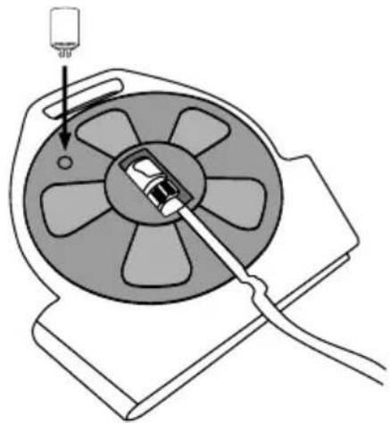
natural_image
Diagram of a mechanical device with a central fan and cable, showing internal components and a pointer (no text or symbols)3.) Remove the spigot adapter from the holder 6
4.) Unwind the hose ^9 completely and remove the spray nozzle connector ^2 from the holder . 3
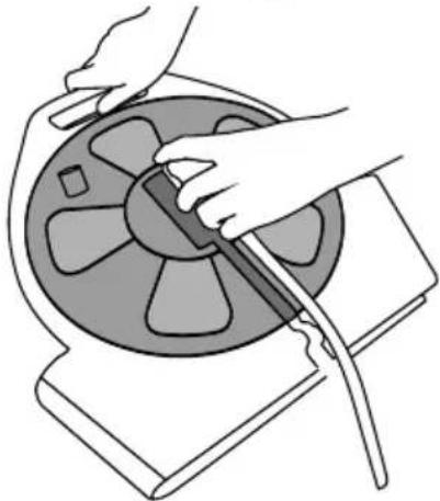
natural_image
Illustration of hands operating a mechanical component with a cable (no text or symbols visible)5.) Unscrew the spigot piece 7 from the spigot adapter 8 and screw it onto the spigot.
6.) Attach the spigot adapter ^8 to the spigot piece ^7
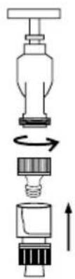
natural_image
Diagram of a mechanical assembly showing a lever, rotating component, and upward force arrow (no text or symbols)7.) Remove the spray nozzle 12 from the holder 11 and attach it to the spray nozzle connector 2.
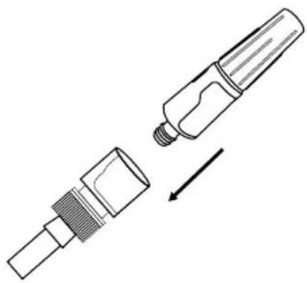
natural_image
Technical line drawing of a mechanical component with an arrow indicating direction (no text or symbols)8.) Turn on the spigot.
9.) After completing your work, turn off the spigot.
10.) Remove the spigot adapter from the spigot piece by loosening and pulling it.
11.) Unscrew the spigot piece ^7 from the spigot and attach it back onto the spigot adapter ^8 .
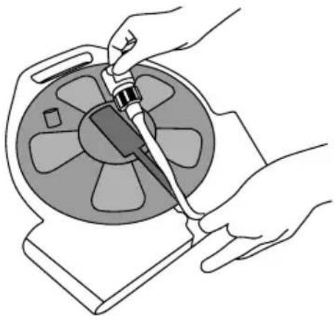
12.) Remove the spray nozzle ^12 from the garden pump sprayer connector ^2 and place the spray nozzle ^14 back in the holder . 11
13.) Guide the hose ^9 through the hose guide ^10 and place the spray nozzle connector ^2 in the holder ^3 .
natural_image
Illustration of hands using a tool to adjust or install a circular device (no text or symbols visible)NOTICE
Before reeling the hose ^9 , make sure that it is completely emptied, otherwise it will not roll up.
14.) Wind up the hose ^9 by turning the hand crank 4 counterclockwise (see arrow on hose reel 1).
15.) Place the spigot adapter 8 back in the holder 6
Using the spray nozzle
You can control the flow of water by turning the front part of the spray nozzle. The spray nozzle can be used to interrupt the flow of water by turning it off completely. Only use this function to temporarily interrupt the flow of water. In such cases, never leave the hose unattended.

Cleaning and storage
■ Clean the housing and the hose with a slightly damp, lint-free cloth. Allow the hose to dry completely before storage.
■ Clean the connections from time to time to ensure a tight fit.
■ Empty the hose and spigot carefully. Store the product at a location safe from frost to prevent frost damage.
Disposal
Dispose of the product via an approved disposal company or through your municipal waste disposal facility. Observe
the legal provisions applicable in your state. If in doubt, contact your waste disposal facility. Ensure that all packaging materials are disposed of in an environmentally sound manner.
Service
GB Service Great Britain
Tel.: 0871 5000 720 (£ 0.10/Min.)
E-Mail: kompernass@lidl.co.uk
IE Service Ireland
Tel.: 1890 930 034
(0,08 EUR/Min., (peak))
(0,06 EUR/Min., (off peak))
E-Mail: kompernass@lidl.ie
IAN 292297
Importer
Please note that the following address is not the service address. Please use the service address provided in the operating instructions.
KOMPERNASS HANDELS GMBH
BURGSTRASSE 21
DE-44867 BOCHUM
GERMANY
www.kompernass.com
Indholdsfortegnelse
Indledning....6
natural_image
Diagram of a mechanical device with a central fan and cable, showing internal components and a pointer (no text or symbols)3.)Tagvandhanetilslutningen u8af holderen. 6
natural_image
Illustration of hands operating a mechanical component with a cable (no text or symbols visible)natural_image
Diagram of a mechanical component with internal parts and directional arrows indicating motion (no text or symbols)natural_image
Technical line drawing of a mechanical component with an arrow indicating assembly (no text or symbols)8.) Åbn for vandhanen.
natural_image
Line drawing of hands using a tool to adjust or install a mechanical component (no text or symbols visible)BEMARK
KOMPERNASS HANDELS GMBH
BURGSTRASSE 21
DE-44867 BOCHUM
TYSKLAND
www.kompernass.com
Table des matières
Introduction....10
natural_image
Diagram of a mechanical device with a central fan and cable, showing internal components and a small component (no text or symbols)natural_image
Illustration of hands operating a mechanical device with a cable (no text or symbols visible)natural_image
Exploded view diagram of a mechanical component showing internal structure and rotation direction (no text or labels)natural_image
Technical line drawing of a mechanical component with an arrow indicating direction (no text or symbols)natural_image
Line drawing of hands using a tool to adjust or install a circular component (no text or symbols visible)REMARQUE
KOMPERNASS HANDELS GMBH
BURGSTRASSE 21
DE-44867 BOCHUM
ALLEMAGNE
www.kompernass.com
Inhoud
Inleiding....14
natural_image
Diagram of a mechanical device with a central fan and cable, showing internal components and a small component (no text or symbols)natural_image
Illustration of hands using a tool to adjust or install a circular component (no text or symbols visible)natural_image
Exploded view diagram of a mechanical component showing internal structure and rotation direction (no text or labels)natural_image
Technical line drawing of a mechanical component with an arrow indicating direction (no text or symbols)8.) Draai de waterkraan open. 9.) Draai na uw werk de waterkraan toe.
natural_image
Illustration of hands using a tool to adjust or install a circular component (no text or symbols visible)OPMERKING
KOMPERNASS HANDELS GMBH
BURGSTRASSE 21
DE-44867 BOCHUM
DUITSLAND
www.kompernass.com
Inhaltsverzeichnis
Einleitung....18
natural_image
Diagram of a mechanical device with a central fan and cable, showing internal components and a small component above (no text or symbols)natural_image
Illustration of hands using a tool to adjust or install a circular component (no text or symbols visible)natural_image
Diagram of a mechanical component with internal parts and directional arrows indicating motion (no text or symbols)natural_image
Technical line drawing of a mechanical component with an arrow indicating direction (no text or symbols)natural_image
Illustration of hands using a tool to adjust or install a mechanical component (no text or symbols visible)HINWEIS
KOMPERNASS HANDELS GMBH
BURGSTRASSE 21
DE-44867 BOCHUM
DEUTSCHLAND
www.kompernass.com
KOMPERNASS HANDELS GMBH
BURGSTRASSE 21
DE-44867 BOCHUM
GERMANY
www.kompernass.com
Last Information Update · Tilstand af information · Version des informations
Stand van de informatie · Stand der Informationen:
10 / 2017 · Ident.-No.: FSTF20A1-102017-1


- FLAT HOSE SET WITH STORAGE REEL FSTF 20 A1
- FLAT HOSE SET WITH STORAGE REEL
- TUYAU PLAT EN BOÎTIERENROULEU- RET ACCESSOIRES
- DK
- Table of Contents
- Introduction....2
- Basic safety instructions....2
- Assembly and connection .... 3
- Introduction
- Intended use
- Equipment
- Package contents
- Technical specifications
- Hose:
- Basic safety instructions
- WARNING! RISK OF ELECTRIC SHOCK!
- Assembly and connection
- NOTICE
- Using the spray nozzle
- Cleaning and storage
- Disposal
- Service
- Importer
- Indholdsfortegnelse
- Indledning....6
- BEMARK
- Table des matières
- Introduction....10
- REMARQUE
- Inhoud
- Inleiding....14
- OPMERKING
- Inhaltsverzeichnis
- Einleitung....18
- HINWEIS
Brand : FLORABEST
Model : FSTF 20 A1
Category : Garden hose