
SRX-T420 - Projector SONY - Free user manual and instructions
Find the device manual for free SRX-T420 SONY in PDF.


| Product Type | Video Projector |
| Model | SRX-T420 |
| Brand | Sony |
| Resolution | 4096 x 2160 (4K) |
| Brightness | 8,000 lumens (approx.) |
| Contrast Ratio | 12,000:1 |
| Light Source | Laser phosphor |
| Lamp Life | 20,000 hours (typical) |
| Dimensions (W x H x D) | 600 x 250 x 700 mm |
| Weight | 35 kg |
| Power Consumption | 1,200 W (max) |
| Input Voltage | 100-240 V AC, 50/60 Hz |
| Lens Options | Interchangeable (4K lenses) |
| Connectivity | HDMI (x2), DisplayPort, HDBaseT, RJ-45, RS-232C |
| Keystone Correction | Vertical & Horizontal |
| Noise Level | 35 dB (typical) |
| Operating Temperature | 5°C to 40°C |
| Installation | Table/ceiling, front/rear |
| Maintenance | Replace air filter periodically |
| Cleaning | Use soft, dry cloth for exterior; lens cleaning kit for optics |
| Safety | Class 1 laser product; do not look into lens |
| Spare Parts | Lamps, filters, lenses available via Sony authorized service |
| Repairability | Professional service recommended |
| Warranty | 3 years (standard) |
Frequently Asked Questions - SRX-T420 SONY
User questions about SRX-T420 SONY
0 question about this device. Answer the ones you know or ask your own.
Ask a new question about this device
Download the instructions for your Projector in PDF format for free! Find your manual SRX-T420 - SONY and take your electronic device back in hand. On this page are published all the documents necessary for the use of your device. SRX-T420 by SONY.
USER MANUAL SRX-T420 SONY
For Customer in China
Operating Instructions

GB
Manufacturer: Sony Corporation
Country of Origin: Japan
Distributor: Sony (China) Limited
Printed on recycled paper.
© 2009 Sony Corporation
For safety
Turn off the power immediately and extinguish the fire.
Meaning of warning symbols
① Exhaust vent (top)
② Air intake / air filter (right side)
① Menu bar
File Password Help
File menu
Places with sudden temperature changes

Conditions not suitable for use
2 Click |Next|.
The license agreement screen will be displayed.

5 Click [Finish].
The installation is complete.

8,109
Signal Adjust
Adjusts the image quality of the input signal.
DCDM, CIE XYZ, CUSTOM: Red (0.6800, 0.3200), Green (0.2650, 0.6900), Blue (0.1500, 0.0600)
Color Temp settings
6500K: White (0.3127, 0.3290)
9300K: White (0.2840, 0.2970)
DCI W/P: White (0.3140, 0.3510)
LKRI-005 (2DVI-D terminal)
Projection lens
Operation Timer....9
P
Signal Adjust 24, 28
Signal Info....24
Signal Mode 24
SQUEEZE....27
Before operating the unit, please read this manual thoroughly and retain it for future reference.
Owner's Record
The model and serial numbers are located on the rear. Record these numbers in the spaces provided below. Refer to these numbers whenever you call upon your Sony dealer regarding this product.
Model No. ____ Serial No. ____
WARNING
To reduce the risk of fire or electric shock, do not expose this apparatus to rain or moisture.
To avoid electrical shock, do not open the cabinet. Refer servicing to qualified personnel only.
WARNING
THIS APPARATUS MUST BE EARTHED.
For the customers in the U.S.A.
This equipment has been tested and found to comply with the limits for a Class A digital device, pursuant to Part 15 of the FCC Rules. These limits are designed to provide reasonable protection against harmful interference when the equipment is operated in a commercial environment. This equipment generates, uses, and can radiate radio frequency energy and, if not installed and used in accordance with the instruction manual, may cause harmful interference to radio communications. Operation of this equipment in a residential area is likely to cause harmful interference in which case the user will be required to correct the interference at his own expense.
You are cautioned that any changes or modifications not expressly approved in this manual could void your authority to operate this equipment.
All interface cables used to connect peripherals must be shielded in order to comply with the limits for a digital device pursuant to Subpart B of Part 15 of FCC Rules.
This device complies with Part 15 of the FCC Rules. Operation is subject to the following two conditions: (1) this device may not cause harmful interference, and (2) this device must accept any interference received, including interference that may cause undesired operation.
For the customers in Canada
This Class A digital apparatus complies with Canadian ICES-003.
For the customers in Europe, Australia and New Zealand
WARNING
This is a Class A product. In a domestic environment, this product may cause radio interference in which case the user may be required to take adequate measures.
For the customers in Europe
The manufacturer of this product is Sony Corporation, 1-7-1 Konan, Minato-ku, Tokyo, Japan. The Authorized Representative for EMC and product safety is Sony Deutschland GmbH, Hedelfinger Strasse 61, 70327 Stuttgart, Germany. For any service or guarantee matters please refer to the addresses given in separate service or guarantee documents.
This apparatus shall not be used in the residential area.
For customers in Norway
This equipment can be connected to an IT power distribution system.
For the State of California, USA only
Perchlorate Material - special handling may apply, See www.dtsc.ca.gov/hazardouswaste/perchlorate Perchlorate Material : Lithium battery contains perchlorate.
For customers in Taiwan only
Please recycle the used battery.
WARNING
Location and Function of Controls....46
Projector Unit 46
Control Function Menu Window 47
Chapter 2 Preparations
Precautions on Installation....49
Unsuitable Installation.... 49
Unsuitable Conditions 50
Installing the SRX Controller in a Computer for Controlling the Projector ....50
System Requirements 50
Installing the SRX Controller.... 51
Connecting a Computer for Controlling the Projector.....53
Connecting the Computer via the Ethernet 53
Connecting the Computer via the RS-232C 54
Starting the SRX Controller ....54
Starting the SRX Controller 54
Changing the Connection Mode.... 55
Connecting the Projector....56
Connecting a Computer Equipped with a DVI-D Connector...... 56
Connecting an HD-SDI Equipment.... 56
Chapter 3 Projecting
Projecting the Picture....58
Projecting a 4K Signal in Quad-Screen Mode .... 59
Chapter 4 Adjustments and Settings Using the SRX Controller
Displaying the Control Function Menu Window ......61
PICTURE CONTROL Window 62
Board 62
Input Source 62
Signal Info (Information) 62
Signal Adjust 62
COLOR/FRAME Window 63
Board 63
Color....63
Frame Adjust 64
INSTALLATION Window....65
LENS CONTROL 65
ELECTRIC V SHIFT FUNCTION.... 65
IMAGE FLIP....65
PROGRESSIVE DISPLAY MODE 65
SQUEEZE 65
LAMP POWER....65
TEST PATTERN 66
SINGLE 3D ADJUST 66
Input Signals And Adjustable/Setting Items ......66
Chapter 5 Others
Recommended Replacement Time ....67
Maintenance....67
Troubleshooting 68
Messages....69
Error Messages 69
Information Messages 71
Specifications 72
Index 75
Overview
1
Chapter
Precautions
On safety
- Operate the unit on 200 V to 240 V AC, 50/60 Hz.
- Should any liquid or solid object fall into the cabinet, unplug the unit and have it checked by your Sony dealer before operating it further.
- Set the power switch to the lower position if it is not to be used for several days.
- The unit is not disconnected from the AC power source (mains) as long as it is connected to the wall outlet and the power switch is set to the upper position.
- Do not look into the lens while the lamp is on.
- Do not place your hand or objects near the ventilation holes. The air coming out is hot.
- Use a lifter to carry the projector to avoid accidents or injury.
- Do not catch your finger between the unit and surface of the floor when moving the projector installed on the floor.
- Be careful not to catch your finger in the cooling fan.
- Since an intense light has come out of this projector from the front, do not stand on the front of a projector for a long time.
On installation
- Allow adequate air circulation to prevent internal heat build-up. Do not place the unit on surfaces (rugs, blankets, etc.) or near materials (curtains, draperies) that may block the ventilation holes. Leave more than 100 cm (39 3/8 inches) of space between the wall and the projector. Be aware that room heat rises to the ceiling; check that the temperature near the installation location is not excessive.
- Install the projector on the floor or hang it from the ceiling. Any other installation causes a malfunction such as color irregularity or a shortened lamp life.
- Do not install the unit in a location near heat sources such as radiators or air ducts, or in a place subject to
direct sunlight, excessive dust or humidity, mechanical vibration or shock.
To avoid moisture condensation, do not install the unit in a location where the temperature may rise rapidly.
On illumination
- To obtain the best picture, the front of the screen should not be exposed to direct lighting or sunlight.
- Ceiling-mounted spot lighting is recommended. Use a cover over fluorescent lamps to avoid lowering the contrast ratio.
- Cover any windows that face the screen with opaque draperies.
- It is desirable to install the projector in a room where floor and walls are not of light-reflecting material. If the floor and walls are of reflecting material, it is recommended that the carpet and wall paper be changed to a dark color.
On preventing internal heat build-up
After turning off the power, the cooling fan runs for about 3 to 15 minutes by detecting an internal temperature while the MAIN and LAMP indicators flash green.
Caution
The projector is equipped with ventilation holes (intake) at the right side, and ventilation holes (exhaust) at the upper and left sides.
Do not block or place anything near these holes, or internal heat build-up may occur, causing picture degradation or damage to the projector.
On cleaning
- To keep the cabinet looking new, periodically clean it with a soft cloth. Stubborn stains may be removed with a cloth lightly dampened with a mild detergent solution. Never use strong solvents, such as thinner, benzene, or abrasive cleansers, since these will damage the cabinet.
- Avoid touching the lens. To remove dust on the lens, use a soft dry cloth. Do not use a damp cloth, detergent solution, or thinner.
On repacking
Save the original shipping carton and packing material; they will come in handy if you ever have to ship your unit. For maximum protection, repack your unit as it was originally packed at the factory.
On "stuck" pixels on an LCD screen
The LCD panel fitted to this unit is manufactured with high precision technology. Thus a very small proportion of pixels may be “stuck,” either always off (black), always on (red, green, or blue), or flashing. In addition, over a long period of use, because of the physical characteristics of the liquid crystal display, such “stuck” pixels may appear spontaneously. These problems are not a malfunction.
On prohibiting continuous lighting
Continuously lighting the Xenon lamp for 24 hours will reduce approximately half of its lamp life. Be sure to turn off the lamp for an hour or more after continuously lighting for 24 hours.
On dangerous areas in a case of lamp explosion
Since a projector lamp can explode, it is dangerous to be in the shaded areas shown in the illustrations below. Keep away from the dangerous areas.
The danger radius (x) differs depending on the height (y) between the bottom of the projector and the floor.
x = 20/3 × √(10y + 6400)
For example, in a case where the height (y) is 800 mm (31 1/2 in.), the danger radius (x) calculated by the formula above is 800 mm (31 1/2 in.)
Left side view

Top view
Location and Function of Controls
Projector Unit
Front/Sides
① Upper side ventilation hole (exhaust)
② Ventilation holes (intake)/air filter (right side)
For replacement of an air filter, consult your Sony dealer.
③ Lens cover
④ Lens mount part
When attaching the optional lens, consult your Sony dealer.
⑤ Input board attachment parts (inside the projector)
Depending on the input sources, install the optional input board in a slot inside the projector. For installation of the board, consult your Sony dealer.
The input board slots are arranged in order of INPUT A, INPUT B, INPUT C and INPUT D from right to left.
INPUT A is preinstalled with an LKRI-005 HDCP DVI board. Depending on the input source, you can replace it with an optional input board.
DVI-D connector (24-pin DVI connector, male): For input of progressive DVI signals and HDCP-compatible DVI signals.
AUX connector (24-pin DVI connector, male):
Used for input extension. For details, consult your Sony dealer.
⑥ Ventilation holes (exhaust) (left side)
Rear
①STATUS MESSAGE window
Displays various messages.
For details on messages, see page 69.
②Status indicators
Combinations of the MAIN and LAMP indicators indicate the status of the projector as follows:
| MAIN indicator | LAMP indicator | Status of the projector |
| ● (red) ● (red) | The projector is in standby mode. You can turn it on with the SRX controller. | |
| ● (green) | ● (green) | The projector is turned on with the SRX controller. You can operate the projector with the SRX controller. |
| ☀ (green) (green) | The projector is in standby after shutting it down with the SRX controller. Cooling fans are running. |
●: Lights ★Flashes
③Power switch
Set the switch to the upper position to turn on the main power of the projector. To turn it off, set the switch to the lower position.
④RS-232C connector (D-sub 9-pin, female)
Connect to the RS-232C connector on a computer in which the supplied SRX Controller is installed. You can control the projector from the computer.
⑤Lamp adjustment windows
The lamp adjustment screws are behind these windows. Fine adjustment of lamp position is necessary after replacing the lamp.
For lamp adjustment, contact your Sony dealer.
Control Function Menu Window
When you install the supplied SRX Controller in your computer, you can operate all of the features of the projector in your computer window. This section explains the functions of the parts for projecting an image on the screen.
For the windows used for the settings and adjustments, see "Adjustments and Settings Using the SRX Controller" on page 61.

①Menu bar
File Password Help
File menu
Selecting "Quit" from the File menu exits the SRX Controller.
Save Log: This item is for service use. For details, consult your Sony dealer.
Password menu
Used to reset the authentication passwords required for displaying the SETTING window and the SERVICE window. The Password menu can be displayed only when an authorized administrator starts the SRX Controller on the computer for controlling the projector.
For details on the SETTING window and the SERVICE window, refer to the Installation Manual for Dealers.
Help menu
Shows the version information of the SRX Controller and the serial number of the projector.
② SCREEN CONTROL window
For details, see "SCREEN CONTROL window" on page 48.
③ Information window

Location: Shows the installation location of the projector that was set in the SETTING window.
Name: Shows the name of the projector that was set in the SETTING window.
Operation Timer: Shows the total operating hours (H) of the projector.
☐ indicator: The bar indicator and the value (%) indicate the proportion of elapsed usage time to the recommended time between replacements.
Warning Info: Displays an error message if there is any warning information on the projector. The same message is displayed in the STATUS MESSAGE window at the rear side of the projector.
④ POWER ON/STANDBY (I/⏻) buttons and POWER indicator
Click "ON" to turn on the projector when the MAIN and LAMP indicators at the rear of the projector are lit in red. Both indicators and the POWER indicator on a computer turn green, and you can operate the projector with the SRX controller on the computer.
To turn off the projector, click "STANDBY" then click "OK" in the displayed confirmation window. The projector enters standby mode, and the indicator flashes green. Even in standby mode, the fans continue to run to reduce internal heat. When the fans stop running, the indicator lights in red.
⑤ FUNCTION 1 to 7 radio buttons
Register the data set or adjusted in the Control Function Menu windows to these buttons, and recall it later to project an image with that setting.
The setting items that can be registered are as follows:
- "INPUT SELECT," "MASKING ADJUST" and "CUT OFF" settings in the SCREEN CONTROL window
- "Input Source" and "Signal Adjust" settings in the PICTURE CONTROL window • "Color" settings in the COLOR/FRAME window
- "ELECTRIC V SHIFT FUNCTION," "SQUEEZE," "PROGRESSIVE DISPLAY MODE," "LAMP POWER" settings, "LENS CONTROL" settings when
the optional lens equipped with zoom/focus memory function is installed, and "3D Gamma Select" and "Position Adjust" of "SINGLE 3D ADJUST" when 3D images are projected, in the INSTALLATION window
For details, see "To register the settings that have been adjusted" on page 61.
⑥ Adjustment/setting window
Clicking the window select button switches the window for the adjustment and setting. The PICTURE CONTROL, COLOR/FRAME and INSTALLATION windows can be displayed.
For details on each window, see "Adjustments and Settings Using the SRX Controller" on page 61.
⑦ Window select buttons
Open the window with the items you want to set or adjust.
SCREEN CONTROL window

①INPUT SELECT radio buttons
Selects the input signal you want to project on the screen.
Input A: Selects the signal input from the connectors on the preinstalled input board in the INPUT A section.
Input B: Selects the signal input from the connectors on the optional input board installed in the INPUT B section.
Input C: Selects the signal input from the connectors on the optional input board installed in the INPUT C section.
Input D: Selects the signal input from the connectors on the optional input board installed in the INPUT D section.
Quad-screen Mode: Selects when you project pictures from four input sources from INPUT A to INPUT D on one screen.
Single 3D buttons: Used for projecting 3D images. For details, contact your Sony dealer.
②MASKING ADJUST section
You can mask the areas of unnecessary portions of the screen.
You can adjust the masking areas with each of six adjustment points.
1 Double-click one of the adjustment points.
The adjustment window opens.

2 Adjust a masking area by clicking the "Horizontal" or "Vertical" 4 buttons or by entering values in both text boxes, while viewing the screen to check the results.
The adjustment ranges for the values are 0 to 950 for the four points at the corners and -500 to 500 for the two points in the center.
3 Repeat steps 1 and 2 to adjust each point while viewing the screen, and mask the screen as necessary.
Clicking the "RESET" button resets all the values to the factory-preset settings.
③MUTING ON/OFF buttons
Clicking the "ON" button cuts off the whole picture on the screen momentarily. Click the "OFF" button to restore the picture. Activating the muting function blocks off lamp light completely by use of a shutter, and displays the black signal on the whole screen.
④ CUT OFF ON/OFF buttons
Used for projecting 3D images. For details, contact your Sony dealer.
Preparations
Chapter
2
Precautions on Installation
Unsuitable Installation
Do not install the projector in the following situations. Such installations may cause a malfunction or damage to the projector.
Poorly ventilated
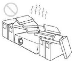
The projector is equipped with ventilation holes for intake and exhaust to prevent internal heat build-up. Do not place the projector in a place where the ventilation holes may be blocked.
Situation that may block the ventilation holes for exhaust

If you put something beside the ventilation holes for exhaust on the side or rear of the projector, the exhaust may be inhaled into the projector through the ventilation holes for intake, causing internal heat build-up and thereby activating the protection circuit. Be sure not to block the ventilation holes for exhaust. Leave a space of more than 1 m (3 9/8 inches) around the unit.
Extremely hot and humid

Location subject to sudden change of temperature

A sudden change of temperature may produce moisture condensation, causing damage to the projector. Take care with heaters or air-conditioners.
Very dusty


Unsuitable Conditions
Do not use the projector under the following conditions.
Laying the unit on its side or upside down
Tilting the unit to the right or left

Avoid tilting the projector more than ±10 degrees. Doing so may cause color shading or shorten the lamp life excessively.
Blocking the ventilation holes

Avoid using a thick-piled carpet or anything that covers the ventilation holes (exhaust/intake). Otherwise, internal heat may build up.
For the locations of the ventilation holes (exhaust/intake), see “Location and Function of Controls” on page 46.
Installing the SRX Controller in a Computer for Controlling the Projector
If you install the supplied SRX Controller in a computer, you can control the projector from the computer.
System Requirements
The following are required to operate the supplied SRX Controller.
- Computer: Intel Pentium M 1.6GHz or higher, and a recommended CPU in your Operating System
- Installed memory: 256 MB or more (512 MB or more recommended), and recommended memory in your Operating System
- Communication: LAN (10BASE-T/100BASE-T) or COM (RS-232C)
- VGA: XGA (1024 × 768) or higher – HDD: Usable memory with 15 MB or more on the built-in hard disk drive
- CD-ROM drive: × 8 or faster
- Operating System: Microsoft Windows XP Professional SP2 (English or Japanese version) (excluding ×64 Edition) or Microsoft Windows Vista Business (English or Japanese version)
Intel and Pentium are registered trademarks of Intel Corporation in the United States and other countries.
Microsoft, Windows XP and Windows Vista are registered trademarks of Microsoft Corporation in the United States and other countries.
User Account Control of Windows Vista
Windows Vista incorporates the User Account Control (UAC) function for improving its security level. As the SRX Controller supports the UAC function, the warning dialog of UAC may be displayed during installation or activation of application.
When the warning dialog is displayed, allow execution of the application in the following procedure. Otherwise, the SRX Controller cannot be executed.
When the unidentified application dialog is displayed
Select "Allow" to allow execution of the application.

Note
If "Cancel" is selected, the application is not executed.
When the administrator password dialog is displayed
Type an administrator password then click "OK."

Installing the SRX Controller
1 Insert the supplied installation disc into the CD-ROM drive of a computer.
The setup.exe in the root folder of the installation disc starts, and the window for preparing the installation appears.

After a while, the wizard of the SRX Controller appears.

2 Click "Next."
The License Agreement window appears.

3 Read the license agreement, click "I accept the terms in the license agreement" if you agree to be bound by the terms, and click "Next."
The select window of the destination folder in which to install the SRX Controller appears.


When you want to install it in the currently displayed folder, click "Next."
If you want to install it in a different folder, click "Change...," specify the folder, click "OK," then click "Next."
The installation start window appears.

4 Click "Install."
The program installation starts.
After a while, the following window appears.

5 Click "Finish."
Installation of the SRX Controller is completed. To restart the SRX Controller immediately after installation has been completed, click to check "Launch SRX Controller for SRX-T series," then click "Finish."
The icon is displayed in the desktop window.
Connecting a Computer for Controlling the Projector
Connect a computer for controlling the projector to the projector via the ethernet cable or via the RS-232C connector.
Connecting the Computer via the Ethernet
Connect the computer to the ethernet cable (supplied) connected to the projector inside.
For connecting the ethernet cable to the projector, consult your Sony dealer.
Note
Set the IP address of the connected computer to be assigned from DHCP.

CAUTION
For safety, do not connect the connector for peripheral device wiring that might have excessive voltage to this port. Follow the instructions for this port.
ATTENTION
If the power of the projector remains on for a long period of time without the ethernet cable connected, the message “Sony Data Projector Initializing…” may appear in the STATUS MESSAGE window while you are setting up for networking after connecting the ethernet cable. This is not a malfunction of the projector.
Connecting the Computer via the RS-232C


Starting the SRX Controller
Starting the SRX Controller
Double-click the icon for the SRX Controller in the desktop window of the computer.
The SRX Controller starts and the Program Launcher screen is displayed.
Note when starting the SRX Controller
When the Operating System of the computer is Windows XP SP2 or later, or any commercially available firewall software is installed in your computer, the following may occur. In these cases, unblock the Windows firewall following the procedures below.
For Windows XP SP2 or later
If the dialog shown below appears when the SRX Controller is started, select "Unblock." When the dialog does not appear but the computer does not access the projector, start "Windows Firewall" from "Control Panel," and then add "SRX Controller" to the list in the "Exceptions" tab.

For commercially available firewall software
Add "SRX Controller" to the Exceptions list, referring to the operating instructions supplied with the software.
About the Program Launcher screen
①Menu bar
File
Select “Quit” from the “File” menu to exit the SRX Controller.
Connect
Selects the connection mode between the projector and the computer for controlling the projector.
For details, see “Changing the Connection Mode” on page 55.
Help
Select “Version” from the “Help” menu to display the version information of the SRX Controller.
②Projector detect window
Information on all of the projectors connected to a network is displayed.
Alert: Shows whether there is any warning information on the projector or not. (: Yes, : No)
Model Name: Model name of the projector
Serial No.: Serial number of the projector
IP Address: IP address of the projector
Connection: Network connection status of the projector. The projectors that can be selected with the SRX Controller are indicated by “Connectable” under “Connection.”
Power: Power on/off status of the projector
Region: Region where the projector is installed
Location: Installation location of the projector
Name: Free name
To exit the SRX Controller
Click "Quit" from the "File" menu on the menu bar.
Changing the Connection Mode
When the projector you want to operate is connected to the computer via a network, you can select it by specifying the IP address of the projector. Connection via the RS-232C is also available.
When connecting the computer via a network by specifying the IP address of the projector
Select “Network” from the “Connect” menu on the menu bar to open the dialog. Enter the IP address and model name of the projector, then click “OK.”
To change the port number, select “PC Port Setting” from the “Connect” menu on the menu bar to display the dialog. Enter the new port number in the dialog and click “OK.”
When connecting the computer via RS-232C
Select “COM” from the “Connect” menu on the menu bar to open the dialog. Enter the port number and model name of the COM port (RS-232C) for the computer, then click “OK.”
Connecting the Projector
When you connect the projector, make sure to:
- Turn off all equipment before making any connections.
- Use the proper cables for each connection.
- Insert the cable plugs firmly; loose connections may increase noise and reduce performance of picture signals. When pulling out a cable, be sure to pull it out from the plug, not the cable itself.
- When installing the optional input board, consult your Sony dealer.
- For connecting the cable to the connector inside the projector, consult your Sony dealer.
Refer also to the instruction manuals of the equipment to be connected.
Connecting a Computer Equipped with a DVI-D Connector
Connect a computer with a DVI-D connector to the optional LKRI-005 HDCP DVI input board attached to any of INPUT A to INPUT D inside the projector.

HDCP (High-bandwidth Digital Content Protection) DVI-D signal can also be input when the input signal with specified resolution is input from LKRI-005.
For details, refer to the Operating Instructions of LKRI-005.
Notes
- According to the input signal type, set "Signal Mode" on "Input Source" in the PICTURE CONTROL window of the SRX Controller. (page 62)
- When an extension cable is used, the signal may not be input correctly due to signal reduction.
- If you input 10-bit signals from a DVI-D connector only (10-bit single mode), a DVI cable compatible with the Dual-link is required.
Connecting an HD-SDI Equipment
Attach the optional LKRI-003 HD-SDI input board inside the projector and connect an HD-SDI equipment to the connectors on the attached input board.

Note
When the LKRI-003 is attached to the projector, select the type of signal with "Signal Mode" of "Input Source" in the
PICTURE CONTROL window. For Single-link input, select "YPbPr" or "YPbPr FULL." For Dual-link input, select "RGB" or "RGB FULL."
For details, see page 62.

Projecting
Chapter
3
Projecting the Picture
Use a computer in which the supplied SRX Controller is installed to project the picture on the screen.


1 Set the power switch at the rear of the projector to the upper position.
The MAIN and LAMP indicators light red and the projector goes into standby mode.
2 Start your computer and double-click the icon of the SRX Controller in the desktop window.
The Program Launcher screen appears.
3 Select the projector you want to operate by double-clicking the projector.
The SRX Controller starts and the Control Function Menu window appears.
Note
When you connect the projectors to the computer via a network, you can also select the projector you want to operate by specifying the IP address of the projector. If connection is made via the RS-232C connector on the projector, specify the RS-232C port number of the computer.
For details, see "Changing the Connection Mode" on page 55.
4 Click the "POWER ON I" button to turn on the projector.
The MAIN and LAMP indicators light green.
5 Turn on the equipment connected to the projector. 6 Select the input signal to be projected on the screen.
Click one of the INPUT SELECT radio buttons on the SCREEN CONTROL window.
Input A: Selects the signal input from the connectors on the preinstalled input board in the INPUT A section.
Input B to Input D: Select the signal input from the connectors on the optional input board in the INPUT B to INPUT D sections, respectively.
Quad-screen Mode: Projects images in quad-screen mode.
Images from four input signals are projected on the screen simultaneously.
The image from signal input from INPUT A is displayed on the upper left of the screen, that of the signal from INPUT B on the upper right, that of the signal from INPUT C on the lower left, and that of the signal from INPUT D on the lower right.
Note
Select the appropriate input signal from “Signal Mode” of “Input Source” in the PICTURE CONTROL window. Improper setting may cause deterioration of the picture.
For details, see page 62.
Notes when quad-screen mode is selected in step 6
- When projecting moving pictures in quad-screen mode, all the input signals should be genlocked to synchronize with each other with a phase difference of less than 5 microseconds. The projected moving picture not synchronized with the reference picture will appear to have dropped frames. A moving picture on the upper left screen for quad-screen mode is regarded as a reference picture. If you project still pictures and moving pictures together, select the upper left screen for the moving picture.
- When projecting signals with vertical frequency of more than 1080 pixels such as UXGA and WUXGA, a part of the displayed image may be invisible.
7 Click the "INSTALLATION" button to open the INSTALLATION window. 8 Adjust the focus with the "Focus +/-" buttons under "LENS CONTROL." 9 Adjust the picture size with the "Zoom +/-" buttons. 10 Adjust the focus again with the "Focus +/-" buttons.
To cut off the whole screen
Click the “ON” button of “MUTING.” The whole screen appears in black. To restore the picture, click the “OFF” button of “MUTING.”
To turn off the power
1. Click the "POWER STANDBY ⏻" button, then the "OK" button in the displayed confirmation dialog.
The MAIN and LAMP indicators flash green. The projector detects the temperature of the lamp and the fan continues to run for 3 to 15 minutes to reduce the internal temperature. When the fan stops running, the MAIN and LAMP indicators light red.
2. Set the power switch to the lower position.
Note
Do not switch the power switch to the lower (off) position while the fan is running. Doing so stops the fan before the temperature of the lamp has been cooled down sufficiently and may damage the unit.
Projecting a 4K Signal in Quad-Screen Mode
4K signals separately input from four input boards can be projected as one 4K image in quad-screen mode. When projecting a 4K image, all the input signals should be genlocked to synchronize with each other with a phase difference of less than 5 μsec. Set “Signal Mode” and “I/P Mode” of “Input Source” in the PICTURE CONTROL window to the same settings for INPUT A to INPUT D. After completing the above, click the “On” radio button with “PROGRESSIVE DISPLAY MODE” in the INSTALLATION window.
Notes
- “PROGRESSIVE DISPLAY MODE” is effective when the signals below are input in the same refresh rate.
- Four 1920 × 1080 signals
- Four 2048 × 1080 signals
- Four SXGA+ (1400 × 1050) signals. "PROGRESSIVE DISPLAY MODE" cannot be selected for any other signals that are not stated.
- Depending on signal types, there are certain limits when displaying the signal. To check whether the signal can be projected as 4K images, see the following table.

| Type of signal LKRI-003 LKRI-005 | ||
| 1080_60i ▲- | ||
| 1024×768_VESA60 - ● | ||
| 1024×768_VESA70 -- | ||
| 1024×768_VESA75 -- | ||
| 1024×768_VESA85 -- | ||
| 1280×960_VESA60 - ● | ||
| 1280×1024_VESA60 - ● | ||
| 1280×1024_VESA75 -- | ||
| 1280×1024_VESA85 -- | ||
| 1600×1200_VESA60 - x | ||
| 1080_50i ▲- | ||
| 720_60P ● ● | ||
| 720_50P ● ● | ||
| 1080_24PsF ○- | ||
| 1400×1050_VESA60 - ○ | ||
| 2048×1080_48i ▲- | ||
| 2048×1080_50i ▲- | ||
| 2048×1080_60i ▲- | ||
| 1080_24P ○ ○ | ||
| 1080_50P - ○ | ||
| 1080_60P - ○ | ||
| 2048×1080_24P | ○ | ○ |
| 2048×1080_25P | ○- | |
| 2048×1080_30P | ○- | |
| 2048×1080_48P | - ○ | |
| 2048×1080_60P | - ○ | |
| 1920×1200_DVI_60 | - × | |
○: Both still pictures and moving pictures can be projected as 4K images. ●: Both still pictures and moving pictures are projected with a line in the center. ▲: Only moving pictures are projected with a line in the center. ×: The picture cannot be projected as 4K images, because the lower portion of the pictures is cut off. -: Both still pictures and moving pictures cannot be projected as 4K images.
Adjustments and Settings Using the SRX Controller
Chapter
4
Displaying the Control Function Menu Window
When you install the supplied SRX Controller in a computer, you can operate the picture adjustments, input signal settings, installation settings, etc. from the computer.
1 Double-click the icon of the SRX Controller in the desktop window of the computer.
The Program Launcher screen appears.
2 Select the projector you want to operate by double-clicking the projector.
The SRX Controller starts and the Control Function Menu window appears.

3 Click any of the "PICTURE CONTROL," "COLOR/FRAME" and "INSTALLATION" buttons to display the desired control window.
For details on each setting window, see the relevant window pages.
To clear the Control Function Menu window
Select "Quit" from the "File" menu on the menu bar, or click the (close) button.
To reset the settings that have been adjusted
Clicking the “RESET” button in the PICTURE CONTROL window resets all the settings of adjustable items for “Signal Adjust” to their factory preset values. To reset the settings of the items for “Frame Adjust” in the COLOR/FRAME window, click the “RESET” button in the COLOR/FRAME window.
To register the settings that have been adjusted
You can register the settings that have been adjusted in the control windows to FUNCTION 1 to 7. As the default setting, the settings are registered to FUNCTION 1. To register the settings to FUNCTION 2 to 7, click one of the FUNCTION 2 to 7 radio buttons, then adjust the items in each window.
You can recall it later to project the picture with the desired setting by clicking one of the FUNCTION radio buttons.
Note
When you click the FUNCTION button to switch to another FUNCTION setting, the picture will be cut off for up to about 10 seconds. The picture with the selected FUNCTION setting will then appear on the screen.
About the items that cannot be adjusted
Items that cannot be adjusted depending on the input signal are not displayed in the window.
For details, see "Input Signals And Adjustable/Setting Items" on page 66.
PICTURE CONTROL Window
The PICTURE CONTROL window is used to select the input source or to adjust the picture quality.
When "Quad-screen Mode" is selected with the INPUT SELECT radio buttons, the items can be independently adjusted for each input channel displayed on the screen.

Board
Shows the input board installed in the relative input board slot of the projector.
Input Source
Signal Mode: Click to open the drop-down list to select the type of signal input from equipment connected to the optional input board.
When the LKRI-005 is installed
Select the input signal type of progressive DVI-D signals.
When used in normal, select "8bit Single Full," which is compatible with DVI1.0 standard and the signal level is Full Range compliance.
When the DTV signal is input, select "8bit Single Limited," which is compatible with DVI1.0 standard and the signal level is Limited Range compliance.
When the 10-bit signal based on Sony's unique specification is input, select "10bit Twin Full" or "10bit Single Full" for a signal of Full Range compliance, or "10bit Twin Limited" or "10bit Single Limited" for a signal of Limited Range compliance.
When the LKRI-003 is installed
For Single-link input, select "YPbPr" or "YPbPr FULL."
For Dual-link input, select "RGB" or "RGB FULL."
When "RGB" or "YPbPr" is selected, in the case that a 10-bit HD-SDI signal is input and "Contrast" is set to 90 in "Signal Adjust" of the PICTURE CONTROL window, mapping is done so that HD-SDI signal data values 1) of 64 to 960 are converted to the video levels of 0 to 100% to display an image on the projector.
When "RGB FULL" or "YPbPr FULL" is selected, in the case that a 10-bit HD-SDI signal is input and "Contrast" is set to 90 in "Signal Adjust" of the PICTURE CONTROL window, mapping is done so that HD-SDI signal data values of 0 to 1023 are converted to the video levels of 0 to 100% to display an image on the projector. In this case, inhibition codes included in a 10-bit HD-SDI signal (data area 0 to 3, and 1020 to 1023) are blocked out.
1) Data value 64 of a 10-bit HD-SDI signal input is equivalent to the video level of 0% (black), and data value 960 equivalent to 100% (white).
I/P Mode: Selects the I/P conversion mode. Depending on the input signal source, set the mode to "Interlace," "PsF" or "1080 50p60p."
Notes
- This item is available with the interlace, PsF or HD 50P/60P signal input.
- When the LKRI-005 is installed, this item is not available.
Signal Info (Information)
Shows the horizontal and vertical frequencies of the input signal automatically. The values are approximate.
The type of the input signal is also displayed.
fH: Displays the horizontal frequency.
fV: Displays the vertical frequency.
Signal Adjust
Adjusts the picture quality of the input signal.
Clicking increases the setting value, and decreases it.

Clicking the "RESET" button resets the following four settings to the factory preset values.
Contrast: Adjusts the picture contrast. The higher the setting, the greater the contrast.
Brightness: Adjusts the picture brightness. The higher the setting, the brighter the picture.
Color: Adjusts the color intensity. The higher the setting, the greater the intensity.
Sharpness: Adjusts the picture sharpness. The higher the setting, the sharper the picture. The lower the setting, the softer the picture.
COLOR/FRAME Window
The COLOR/FRAME window is used to adjust the input signal.
When "Quad-screen Mode" is selected with the INPUT SELECT radio buttons, the items can be independently adjusted for each input channel displayed on the screen.

Board
Shows the input board installed in the relative input board slot of the projector.
Color
Adjusts the items so that you can obtain precise color reproduction.
If the color of an image is not correct, check the setting of "Color Space" first.
Select the setting from the drop-down list displayed by clicking ▼.
Color Space: Selects the color gamut.
sRGB(709): Select when projecting a normal high-definition signal or RGB signal.
DCDM: Select when projecting a signal source using the Minimum D-Cinema Color Gamut defined by the DCI Specifications Book/Version 1.0.
CIE XYZ: Select when projecting an XYZ signal from LKRI-003.
Note
Set "Signal Mode" of "Input Source" in the PICTURE CONTROL window to "RGB FULL."
Adobe RGB: Select when projecting Adobe RGB compatible computer signals.
CUSTOM: Select when projecting a signal using the color gamut defined by the user. The default value is the same as DCDM.
Color Temp (temperature): Selects the color
temperature from among "DCI W/P," "6500K,"
"9300K," "CUSTOM1," "CUSTOM2" and
"CUSTOM3." 6500K is preset in CUSTOM1 to 3 settings in the factory.
"6500K" is recommended for a normal high-definition signal or RGB signal. Set this item to "DCI W/P" to project a movie source.
Gamma: Selects a gamma correction curve. The smaller the value, the brighter the image. "2.2" is recommended to project a normal high-definition signal or RGB signal.
Select "2.6" or "2.2," or set a value from 1.80 to 2.59 (except 2.20) in 0.01 steps according to the signal input. This allows projection of an image with optimum brightness.
To set the gamma value in 0.01 steps, set "Gamma" to "1.8," and click the "CUSTOMIZE" button. Input the values in the Input Gamma Data screen and press the "OK" button.

When a signal is input from the connector on the LKRI-005
When you set each item in "Color," the setting will be written to the color space description area of the EDID ROM.
The values to be written to the EDID ROM are shown below.
Color Space settings
sRGB(709): Red (0.6400, 0.3300), Green (0.3000, 0.6000), Blue (0.1500, 0.0600)
Adobe RGB: Red (0.6400, 0.3300), Green (0.2100, 0.7100), Blue (0.1500, 0.0600)
DCDM, CIE XYZ, CUSTOM: Red (0.6800, 0.3200), Green (0.2650, 0.6900), Blue (0.1500, 0.0600)
Color Temp settings
6500K: White (0.3127, 0.3290)
9300K: White (0.2840, 0.2970)
DCI W/P: White (0.3140, 0.3510)
CUSTOM1 to CUSTOM3: White (0.3127, 0.3290) (default values)
Gamma settings
2.6: 2.6
2.2: 2.2
CUSTOMIZE: Value set using CUSTOMIZE
Frame Adjust
Adjusts the horizontal size and the position of the picture.
Clicking increases the setting value, and decreases it.

Clicking the “RESET” button resets all the settings of “Frame Adjust” to the factory-preset values.
Dot Phase: Adjusts the phase of the SXRD panels and the input signal. Adjust the value to obtain the clearest picture. The item does not function with this projector.
H Size: Adjusts the horizontal size of the picture according to the input signal. As the setting value increases, the horizontal size of the picture becomes larger. This item does not function with this projector.
H Shift: Adjusts the horizontal position of the picture. As the setting value increases, the picture moves to the right. As the value decreases, the picture moves to the left.
V Shift: Adjusts the vertical position of the picture. As the setting value increases, the picture moves up. As the value decreases, the picture moves down.
Note
If the position of the picture is not adjusted correctly, noise may appear in the blank portion of the screen. This is not a malfunction of the projector. Adjust the picture position correctly with "Frame Adjust."
INSTALLATION Window
The INSTALLATION window is used to adjust the projected picture and to change the lamp output, etc.

LENS CONTROL
Adjusts the projected picture on the screen.
Zoom +/-: Adjusts the size of the picture. Clicking + enlarges the picture size, and clicking - reduces the picture size.
Focus +/-: Adjusts the picture focus. Clicking + focuses on a picture further back. Clicking - focuses on a forward picture.
ELECTRIC V SHIFT FUNCTION
Adjusts the vertical position of the projected pictures electrically. As the setting value increases, the picture moves upward. As the setting value decreases, the picture moves downward.
Clicking the "RESET" button resets the setting to the factory-preset values.
Notes
• This function is effective in the following cases:
- When single-screen mode is selected
- When quad-screen mode is selected and
"PROGRESSIVE DISPLAY MODE" is set to "On"
- When this function is used for quad-screen mode, all the projected signals should be genlocked to synchronize with each other with a phase difference of less than 5 μsec. If they are not synchronized, the picture is not displayed correctly.
IMAGE FLIP
Flips the picture.
Select it from the drop-down list displayed by clicking according to the installed condition of the projector.
Off: Normal projection
H: Flips the picture horizontally
V: Flips the picture vertically
HV: Flips the picture horizontally and vertically
![graph TD A["F"] --> B["F"] A --> C["E"] C --> D["H"] style A fill:#f9f,stroke:#333 style B fill:#f9f,stroke:#333 style C fill:#f9f,stroke:#333 style D fill:#f9f,stroke:#333](/content/2026/05/871835/images/8266484c16a8601e6d186263f21be87c998b730aa50406fd3b0e52e5f5861d70.jpg)
PROGRESSIVE DISPLAY MODE
Normally, click the "Off" radio button.
Click the “On” radio button when the signals from four input boards are used to project a 2048 (1920) × 1080-pixel signal as a 4096 (3840) × 2160-pixel 4K image or to project a 1400 × 1050-pixel (SXGA+) signal as a 2800 × 2100-pixel image in single-screen mode.
SQUEEZE
This function allows the input signal to be displayed on the screen in a converted aspect ratio.
When you click the “On” radio button, the 720p, 1920 × 1080 or 2048 × 1080 signal with a 16:9 aspect ratio can be displayed by stretching to a 2.39:1 aspect ratio.
When you click the "Off" radio button, the input signal is displayed without converting the aspect ratio.
Note
This function is available only for projection in single-screen mode.
LAMP POWER
Adjusts the lamp power output.
Lamp Power: You can reduce the lamp power to a value from 53% to 100% in increments of 1% using the + or - button.
Luminance Value: The value is referred to when your Sony service representative performs axis adjustments after replacing the lamp.
Note
Switching the lamp output frequently may reduce the lamp life. Use of the defined lamp output is recommended.
TEST PATTERN
Displays a built-in test pattern on the screen for adjusting the picture with no signal input from external equipment. Click the radio button of the desired test pattern from among “Cross Hatch,” “Cross Hatch (Invert),” “Checker Flag” and “Test mode 1 (all white).” When you do not display a built-in test pattern, click the “Off” radio button.
Notes
- While a built-in test pattern is displayed on the screen, you cannot switch the INPUT SELECT radio button, and cannot adjust the PICTURE CONTROL and COLOR/FRAME settings.
- “Single 3D” is used for projecting a 3D image. For details, contact your Sony Dealer.
SINGLE 3D ADJUST
Used to project a 3D image.
For details, contact your Sony Dealer.
Input Signals And Adjustable/Setting Items
Some items of “Signal Adjust” in the PICTURE CONTROL window and “Frame Adjust” in the COLOR/FRAME window are not adjusted or set depending on the input signals. Items that cannot be adjusted depending on the input signal are not displayed in the window.
Signal Adjust
| Item | Input signal | ||
| HD-SDI DVI-D 4K | |||
| Contrast ● | ● | ● | |
| Brightness ● | ● | ● | |
| Color ●– | – | ||
| Sharpness ●– | – | ||
●: Adjustable/can be set
-: Not adjustable/cannot be set
Frame Adjust
| Item | Input signal | |||
| HD-SDI DVI-D 4K | ||||
| D | o | t | P | h |
| H | S | i | z | e |
| H Shift | ● | ● | - | |
| V Shift | ● | ● | - | |
●: Adjustable/can be set
-: Not adjustable/cannot be set
Recommended Replacement Time
Recommended usage time of the LKRX-2042A projection lamp is approximately 500 hours.
The bar of the indicator in the Control Function Menu window becomes red when the time for replacement is coming near. The percentage indicates the time used before the recommended time for replacement. Use them as a guide.
Be sure to ask your Sony dealer to replace a projection lamp.
Maintenance
Some components of the projector are consumable parts over a long period of use.
To keep the projector working properly and to prolong its usable lifetime, have the projector inspected periodically.
We recommend you make a maintenance contract for periodical inspection with us. For details on the contract, consult with your Sony dealer.
Troubleshooting
If the projector appears to be operating erratically, try to diagnose and correct the problem using the following guide. If the problem still persists, consult your Sony dealer.
Power
| Symptom Cause Remedy | ||
| Power is not turned on. The main power is turned off. Set the power switch at the rear of the projector to the upper position (page 58). | ||
Picture
| Symptom Cause Remedy | ||
| No picture. Cables are disconnected. Check that the proper connection has been made (page 56). | ||
| The picture is cut off. Click the “OFF” button of “MUTING” in the SCREEN CONTROL window (page 59). | ||
| Ambient temperature is high. Reduce the room temperature so that it becomes within the operating temperature (5°C to 35°C). | ||
| Color balance is incorrect. | Incorrect input source mode is selected. | Set “Signal Mode” of “Input Source” in the PICTURE CONTROL window correctly (page 62). |
| The picture is too dark. Contrast and brightness has not been adjusted properly. | Adjust the “Contrast” or “Brightness” in the PICTURE CONTROL window (page 62). | |
| A line appears in the center of a projected 4K image. | The input signal is not suitable to be projected as a 4K image. | Check that the signal can be projected as a 4K image (page 60). |
SRX Controller
| Symptom Cause Remedy | ||
| The “Control Function Menu” window does not appear. | The projector and a computer for controlling the projector are disconnected. | Check that the proper connection between the projector and a computer has been made (page 53). |
Messages
The messages are displayed in the STATUS MESSAGE window at the rear of the projector.
Displayed messages are classified into "Error messages" and "Information messages."
The error messages are also displayed under "Warning Info" in the "Control Function Menu" window of the SRX Controller.

Error Messages
Error messages are classified into three types, described below, depending on the danger level.
If an error occurs, the message number and the message are displayed in the STATUS MESSAGE window.
ALERT: Danger level - High
Message number: ALERT_xx
WARNING: Danger level - Middle
Message number: WARN_xx
FAILURE: Danger level - Low
Message number: FAIL_xx
If an error message is displayed, contact your Sony dealer and give them the message and its number.
ALERT: Danger level - High
| Message number | Error message Meaning | |
| ALERT_01 BOARD | ERROR Trouble with power of IFA board | |
| ALERT_02 BOARD | ERROR Trouble with power of IFB board | |
| ALERT_03 BOARD | ERROR Trouble with power of IFC board | |
| ALERT_04 BOARD | ERROR Trouble with power of IFD board | |
| ALERT_05 BOARD | ERROR Trouble with power of MX board | |
| ALERT_06 BOARD | ERROR Trouble with power of LPD board | |
| ALERT_07 BOARD | ERROR Trouble with power of CT board | |
| ALERT_08 BOARD | ERROR Trouble with power of DST board | |
| ALERT_09 BOARD | ERROR Trouble with power of PR1 board |

| Message number | Error message | Meaning |
| ALERT_10 BOARD | ERROR Trouble with power of PR2 board | |
| ALERT_11 BOARD | ERROR Trouble with power of SY board | |
| ALERT_12 BOARD | DETACHED CN board disconnected | |
| ALERT_13 BOARD | DETACHED MX board disconnected | |
| ALERT_14 BOARD | DETACHED LPD board disconnected | |
| ALERT_15 BOARD | DETACHED CT board disconnected | |
| ALERT_16 BOARD | DETACHED DST board disconnected | |
| ALERT_17 BOARD | DETACHED PR1 board disconnected | |
| ALERT_18 BOARD | DETACHED PR2 board disconnected | |
| ALERT_19 TEMPERATURE | R Temperature of R panel is too high, and the unit stops operation. | |
| ALERT_20 TEMPERATURE | R Temperature of G panel is too high, and the unit stops operation. | |
| ALERT_21 TEMPERATURE | R Temperature of B panel is too high, and the unit stops operation. | |
| ALERT_22 COVER | DETACHED Rear cover detached and/or internal mirror position changed | |
| ALERT_27 FAN ERROR | Abnormal in fan A for lamp | |
| ALERT_28 FAN ERROR | Abnormal in fan B for lamp | |
| ALERT_29 FAN ERROR | Abnormal in fan C for lamp | |
| ALERT_30 FAN ERROR | Abnormal in fan D for lamp | |
| ALERT_32 BALLAST | R Temperature of lamp power is too high, and the unit stops operation. | |
| ALERT_33 BALLAST | R Abnormal in the fans for lamp power | |
| ALERT_34 BALLAST | R Abnormal in the lamp power | |
| ALERT_35 LAMP ERROR | The lamp does not light, or goes out. | |
| ALERT_36 BALLAST | R Abnormal in the lamp power | |
| ALERT_37 COVER | DETACHED Abnormal position of the lamp house cover | |
| ALERT_38 BOARD | R Error Trouble with power of CN board | |
| ALERT_39 TEMPERATURE | R Temperature of 8-inch duct attachment part is too high, and the unit stops operation. | |
| ALERT_41 COVER | DETACHED Filter duct is detached, and the unit stops operation. |
WARNING: Danger level – Middle
| Message number | Error message | Meaning |
| WARN_01 | FAN ERROR | Abnormal in fan 1 for the main power |
| WARN_02 | FAN ERROR | Abnormal in fan 2 for the main power |
| WARN_05 | FAN ERROR | Abnormal in fan 1 for board |
| WARN_06 | FAN ERROR | Abnormal in fan 2 for board |
| WARN_12 | FAN ERROR | Abnormal in fan for peltier R |
| WARN_13 | FAN ERROR | Abnormal in fan for peltier G |
| WARN_14 | FAN ERROR | Abnormal in fan for peltier B |
| WARN_20 | DEVICE ERROR | Failure of the peltier R control |
| WARN_21 | DEVICE ERROR | Failure of the peltier G control |
| WARN_22 | DEVICE ERROR | Failure of the peltier B control |
| WARN_23 | CONNECTOR DETACHED | The peltier R connector disconnected |
| WARN_24 | CONNECTOR DETACHED | The peltier G connector disconnected |
| WARN_25 | CONNECTOR DETACHED | The peltier B connector disconnected |
| WARN_26 | DOUSER ERROR | Trouble with the douser operation |
| WARN_27 | BALLAST ERROR | Failure of the ballast communication for the lamp power |
| Message number | Error message Meaning | |
| WARN_28 BALLAST | ERROR Incorrect settings of the lamp S/N | |
| WARN_30 COVER | DETACHED Filter duct is detached | |
| WARN_31 FAN ERROR | OR Abnormal in fan for PS2 | |
| WARN_32 FAN ERROR | OR Abnormal in fan for PS1 | |
| WARN_33 FAN ERROR | OR Abnormal in fan for PBS |
FAILURE: Danger level - Low
| Message number | Error message Meaning | |
| FAIL_02 TEMPERATURE | ERROR Warning for abnormal | temperature of 8-inch duct |
| FAIL_04 TEMPERATURE | ERROR Temperature of the intakes is too high. | |
| FAIL_06 TEMPERATURE | ERROR Temperature of the optical unit area is too high. | |
| FAIL_10 TEMPERATURE | ERROR Warning for abnormal | temperature of Panel R |
| FAIL_11 TEMPERATURE | ERROR Warning for abnormal | temperature of Panel G |
| FAIL_12 TEMPERATURE | ERROR Warning for abnormal | temperature of Panel B |
| FAIL_15 TEMPERATURE | ERROR Warning for abnormal | temperature of the lamp power |
| FAIL_16 LENS ERROR | Failure of the zoom position adjustment to the registered setting | |
| FAIL_17 LENS ERROR | Failure of the lens focus adjustment to the registered setting | |
| FAIL_18 | LENS ERROR Trouble with the zoom position adjustment | |
| FAIL_19 | LENS ERROR Trouble with the lens focus adjustment | |
| FAIL_21 | ADJUSTMENT ERROR | Abnormal in the Z-axis adjustment |
| FAIL_25 DEVICE ERROR | Failure of FPGA configuration | |
| FAIL_26 | DEVICE ERROR | Trouble with the IIC circuit |
| FAIL_27 | DEVICE ERROR | Trouble with the LVDS circuit |
| FAIL_28 | DEVICE ERROR | Trouble with the PLL circuit |
| FAIL_29 | DEVICE ERROR | Trouble with the PARITY circuit |
| FAIL_30 | BALLAST ERROR | Lamp power interlocked |
| FAIL_36 | DEVICE ERROR | Error of the DVI setting |
Information Messages
The message number is not displayed for information messages. Check the following if a message appears in the STATUS MESSAGE window.
| Message | Meaning |
| LOW REAL TIME CLOCK BATTERY | The RTC battery (BT200) for the SY board should be replaced. |
| LAMP ALERT | The recommended usage time of the projection lamp has passed. |
| AIR FILTER WARNING OPTICAL | The recommended usage time of the optical air filter has passed. |
Specifications
Optical characteristics
Projection system
SXRD (Silicon X-tal Reflective Display)
3 panel prism color integration system
SXRD 8,847,360 pixels (4096 × 2160 × 3)
Lens Optional
Light output 21,000 lm (center)
19,000 lm
Lamp 4.2 kW Xenon lamp (not supplied)
Electrical characteristics
Acceptable signal
XGA, Quad-VGA, SXGA, SXGA+,
UXGA, WUXGA, 1920 × 1080, 2048
× 1080 (when the LKRI-005 HDCP
DVI input board is installed)
HD-SDI (SMPTE Serial Digital Interface standard) (when the LKRI-003 HD-
SDI (4:4:4) input board is installed)
Input/Output
DVI-D DVI connector, 24-pin (male) (For
details, see "Pin assignment" on page 73.)
AUX DVI connector, 24-pin (male) (For
details, see "Pin assignment" on page 73.)
RS-232C D-sub 9-pin (female) (For details, see
"Pin assignment" on page 73.)
ETHERNET 10BASE-T/100BASE-T
Input signal
Preinstalled board (LKRI-005)
XGA, Quad-VGA, SXGA, SXGA+,
UXGA, WUXGA, 1920 × 1080, 2048
× 1080
When the LKRI-003 is installed
SMPTE Format HD-SDI/DC-SDI/Dual-
link HD-SDI/Dual-link DC-SDI
When the LKRI-005 is installed
XGA, Quad-VGA, SXGA, SXGA+,
UXGA, WUXGA, 1920 × 1080, 2048
× 1080
General
Dimensions Approx. 700 × 640 × 1250 mm (27 5/8 ×
25 1/4 × 49 1/4 inches) (w/h/d)
(excluding the optional lens and main unit's projecting parts)
Mass Approx. 181 kg (399 lb) (excluding the optional lamp and lens)
Power requirements
200 to 240 V AC, 50/60 Hz
Power consumption
Max. approx. 5.4 kW
(Standby mode: 29 W)
Current consumption
27 to 22.5 A
Operating temperature
5°C to 35°C (41°F to 95°F) (About 20
minutes of aging is recommended to
provide better quality picture.)
Performance guarantee temperature
10°C to 30°C (50°F to 86°F)
Operating humidity
35% to 85% (no condensation)
Storage temperature
-20°C to +60°C (-4°F to +140°F)
Storage humidity
10% to 90%
Supplied accessories
SRX Controller (CD-ROM) (1)
Ethernet cable (1-830-803-12 (Sony)) (1)
Lens cover (1 set)
M8 screws for lens mounting (4)
Attachment board for the LKRI-003 (4)
Attachment board for the LKRI-005 (3)
Keys (4)
Operating Instructions (1)
Optional accessories
Projection lamp
LKRX-2042A
HD-SDI (4:4:4) input board
LKRI-003 (HD-SDI input/output with 4 BNC-type connectors)
HDCP DVI input board
LKRI-005 (2 DVI-D input connectors)
Projection lens LKRL-Z111C, LKRL-Z114C, LKRL-
Z116C, LKRL-Z117, LKRL-Z119,
LKRL-Z122, LKRL-Z115, LKRL-
Z140, LKRL-90
(For details, refer to the Operating
Instructions of each projection lens.)
Equipment complying with IEC 61000-3-12
Design and specifications are subject to change without notice.
Note
Always verify that the unit is operating properly before use. SONY WILL NOT BE LIABLE FOR DAMAGES OF ANY KIND INCLUDING, BUT NOT LIMITED TO, COMPENSATION OR REIMBURSEMENT ON ACCOUNT OF THE LOSS OF PRESENT OR PROSPECTIVE PROFITS DUE TO FAILURE OF THIS UNIT, EITHER DURING THE WARRANTY PERIOD OR AFTER EXPIRATION OF THE WARRANTY, OR FOR ANY OTHER REASON WHATSOEVER.
Pin assignment
RS-232C connector (D-sub 9-pin, female)

| Pin number | Signal name Meaning | |
| 1 | NC | |
| 2 RD Received Data | ||
| 3 TD Transmit Data | ||
| 4 | DTRa) | Data Terminal Ready |
| 5 GND Ground | ||
| 6 | DSRa) | Data Set Ready |
| 7 | RTSb) | Request to Send |
| 8 | CTSb) | Clear to send |
| 9 | NC | |
a) Circuit between pins 4 and 6 is short-circuited in the projector. b) Circuit between pins 7 and 8 is short-circuited in the projector.
DVI-D connector, AUX connector (24-pin, male)

| Pin number Signal name | |
| 1 | D A |
| 2 | D A |
| 3 | GND |
| 4 | D A |
| 5 | D A |
| 6 | DDC_SCL |
| 7 | DDC_SDA |
| 8 | NC |
| 9 | D A |
| 10 | DATA1+ |
| 11 | GND |
| 12 | DATA3- |
| 13 | DATA3+ |
| 14 | +5V |
| 15 | DDC_GND |
| 16 | HOTPLUG_DET |
| 17 | DATA0- |
| 18 | DATA0+ |
| 19 | GND |
| 20 | DATA5- |
| 21 | DATA5+ |
| 22 | GND |
| 23 | CLK+ |
| 24 | CLK- |

Preset Signals Displayed image size in multiple screen
| Preset signal | fH (kHz) | fV (Hz) | Aspect ratio |
| HDTV 33.75 60.00 16:9 | |||
| 1024 × 768_VESA60 48.36 | 60.00 4:3 | ||
| 1024 × 768_VESA70 56.48 | 70.07 4:3 | ||
| 1024 × 768_VESA75 60.02 | 75.03 4:3 | ||
| 1024 × 768_VESA85 68.68 | 85.00 4:3 | ||
| 1280 × 960_VESA60 60.00 | 60.00 4:3 | ||
| 1280 × 1024_VESA60 63.97 | 60.01 5:4 | ||
| 1280 × 1024_VESA75 79.98 | 75.03 5:4 | ||
| 1280 × 1024_VESA85 91.15 | 85.02 5:4 | ||
| 1600 × 1200_VESA60 75.00 | 60.00 4:3 | ||
| 720/60P 45.00 60.00 16:9 | |||
| 720/50P 37.50 50.00 16:9 | |||
| 1080/48I (24PsF) 27.00 48.00 | 16:9 | ||
| 1080/50I 28.13 50.00 16:9 | |||
| 1080_24P 27.00 24.00 16:9 | |||
| DC2048 × 1080_48I | 27.00 48.00 | - | |
| DC2048 × 1080_24P | 27.00 24.00 | - | |
| 1400 × 1050_60p | 65.30 60.00 | 4:3 | |
| 1920 × 1080_60p | 67.50 60.00 | 16:9 | |
| 1920 × 1200_60p | 74.038 60.00 | - | |
| 2048 × 1080_48p | 54.00 48.00 | - | |
| 2048 × 1080_60p | 67.50 60.00 | - |
mode
Unit: pixel
| Screen modeType of signal | Single screen | Quad screen | ||
| Horizontal size | Vertical size | Horizontal size | Vertical size | |
| XGA | 2849 | 2137 | 1432 | 1074 |
| SXGA1 | 2560 | 2048 | 1280 | 1024 |
| SXGA2 | 2560 | 1920 | 1280 | 960 |
| SXGA+ 2800 | 2100 | 1400 | 1050 | |
| UXGA a) | 2864 | 2148 | - | - |
| WUXGA a) | 3437 | 2148 | - | - |
| 720p | 3810 | 2143 | 1916 | 1077 |
| HD | 3840 | 2160 | 1920 | 1080 |
| 2K | 4096 | 2160 | 2048 | 1080 |
| 4K | 4096 | 2160 | - | - |
a) When projecting signals with vertical frequency of more than 1080 pixels such as UXGA and WUXGA in quad-screen mode, a part of the displayed image may be invisible.
Index
A
Adjustments and Settings Using the SRX Controller 61
B
Board 62, 63
Brightness 62
C
Color 63
Color Space 63
Color Temp 64
COLOR/FRAME window 63
Connection mode 55
Connections
computer equipped with a DVI-D connector 56
computer for controlling the projector 53
HD-SDI equipment 56
Contrast 62
Control Function Menu window 47, 61
CUT OFF 48
D
Displayed image size in multiple screen mode 74
Dot Phase 64
E
ELECTRIC V SHIFT FUNCTION 65
Error Messages 69
Ethernet connector 53
F
fH 62
Focus 59,65
Frame Adjust 64, 66
FUNCTION 1-7 61
fV 62
G
Gamma 64
H
H Shift 64
H Size 64
|
I/P Mode 62
IMAGE FLIP 65
INPUT SELECT 48, 59
Input Signals And Adjustable/Setting Items 66
Input Source 62
INSTALLATION window 65
L
LAMP POWER 65
LENS CONTROL 65
Location and Function of Controls Control Function Menu window 47
Front/Sides 46
Rear 46
M
Maintenance 67
MASKING ADJUST 48
Messages 69
MUTING 48,59
0
Operation Timer 47
Optional accessories 72
P
PICTURE CONTROL window 62
Precautions 44
Program Launcher screen 55
PROGRESSIVE DISPLAY MODE 65
Projecting a 4K Signal in Quad-screen Mode 59
Projecting the Picture 58
Q
Quad-screen Mode 48, 59
R
Recommended Replacement Time 67
Registering the settings 61
Resetting the settings 61
RS-232C connector 54, 73
S
Save Log 47
SCREEN CONTROL window 48
Sharpness 63
Signal Adjust 62, 66
Signal Info 62
Signal Mode 62
Specifications 72
SQUEEZE 65
SRX Controller
Adjustments and settings 61
Exiting 55
Installing 50
Starting 54
STATUS MESSAGE window 69
Supplied accessories 72
T
TEST PATTERN 66
Troubleshooting 68
V
V Shift 64
Ventilation holes 46
Z
Zoom 65



- FOR SAFETY
- MEANING OF WARNING SYMBOLS
- ① EXHAUST VENT (TOP)
- ② AIR INTAKE / AIR FILTER (RIGHT SIDE)
- FILE MENU
- PLACES WITH SUDDEN TEMPERATURE CHANGES
- CONDITIONS NOT SUITABLE FOR USE
- CLICK [FINISH]
- SIGNAL ADJUST
- COLOR TEMP SETTINGS
- P
- OWNER'S RECORD
- WARNING
- THIS APPARATUS MUST BE EARTHED
- FOR THE CUSTOMERS IN THE U.S.A
- FOR THE CUSTOMERS IN CANADA
- FOR THE CUSTOMERS IN EUROPE, AUSTRALIA AND NEW ZEALAND
- FOR THE CUSTOMERS IN EUROPE
- FOR CUSTOMERS IN NORWAY
- FOR THE STATE OF CALIFORNIA, USA ONLY
- FOR CUSTOMERS IN TAIWAN ONLY
- CHAPTER 2 PREPARATIONS
- CHAPTER 3 PROJECTING
- CHAPTER 4 ADJUSTMENTS AND SETTINGS USING THE SRX CONTROLLER
- COLOR/FRAME WINDOW
- INSTALLATION WINDOW
- INPUT SIGNALS AND ADJUSTABLE/SETTING ITEMS
- CHAPTER 5 OTHERS
- OVERVIEW
- CHAPTER
- PRECAUTIONS
- ON SAFETY
- ON INSTALLATION
- ON ILLUMINATION
- ON PREVENTING INTERNAL HEAT BUILD-UP
- CAUTION
- ON CLEANING
- ON REPACKING
- ON "STUCK" PIXELS ON AN LCD SCREEN
- ON PROHIBITING CONTINUOUS LIGHTING
- ON DANGEROUS AREAS IN A CASE OF LAMP EXPLOSION
- LEFT SIDE VIEW
- LOCATION AND FUNCTION OF CONTROLS
- PROJECTOR UNIT
- CONTROL FUNCTION MENU WINDOW
- ①MENU BAR
- PASSWORD MENU
- HELP MENU
- ② SCREEN CONTROL WINDOW
- ③ INFORMATION WINDOW
- ④ POWER ON/STANDBY (I/⏻) BUTTONS AND POWER INDICATOR
- ⑤ FUNCTION 1 TO 7 RADIO BUTTONS
- ⑥ ADJUSTMENT/SETTING WINDOW
- ⑦ WINDOW SELECT BUTTONS
- SCREEN CONTROL WINDOW
- ①INPUT SELECT RADIO BUTTONS
- ②MASKING ADJUST SECTION
- ③MUTING ON/OFF BUTTONS
- ④ CUT OFF ON/OFF BUTTONS
- PREPARATIONS
- PRECAUTIONS ON INSTALLATION
- UNSUITABLE INSTALLATION
- POORLY VENTILATED
- SITUATION THAT MAY BLOCK THE VENTILATION HOLES FOR EXHAUST
- EXTREMELY HOT AND HUMID
- LOCATION SUBJECT TO SUDDEN CHANGE OF TEMPERATURE
- VERY DUSTY
- UNSUITABLE CONDITIONS
- TILTING THE UNIT TO THE RIGHT OR LEFT
- BLOCKING THE VENTILATION HOLES
- INSTALLING THE SRX CONTROLLER IN A COMPUTER FOR CONTROLLING THE PROJECTOR
- SYSTEM REQUIREMENTS
- USER ACCOUNT CONTROL OF WINDOWS VISTA
- WHEN THE UNIDENTIFIED APPLICATION DIALOG IS DISPLAYED
- NOTE
- WHEN THE ADMINISTRATOR PASSWORD DIALOG IS DISPLAYED
- INSTALLING THE SRX CONTROLLER
- CLICK "INSTALL
- CLICK "FINISH
- CONNECTING A COMPUTER FOR CONTROLLING THE PROJECTOR
- CONNECTING THE COMPUTER VIA THE ETHERNET
- ATTENTION
- CONNECTING THE COMPUTER VIA THE RS-232C
- STARTING THE SRX CONTROLLER
- NOTE WHEN STARTING THE SRX CONTROLLER
- FOR WINDOWS XP SP2 OR LATER
- FOR COMMERCIALLY AVAILABLE FIREWALL SOFTWARE
- FILE
- CONNECT
- HELP
- ②PROJECTOR DETECT WINDOW
- TO EXIT THE SRX CONTROLLER
- CHANGING THE CONNECTION MODE
- WHEN CONNECTING THE COMPUTER VIA A NETWORK BY SPECIFYING THE IP ADDRESS OF THE PROJECTOR
- WHEN CONNECTING THE COMPUTER VIA RS-232C
- CONNECTING THE PROJECTOR
- WHEN YOU CONNECT THE PROJECTOR, MAKE SURE TO
- CONNECTING A COMPUTER EQUIPPED WITH A DVI-D CONNECTOR
- NOTES
- CONNECTING AN HD-SDI EQUIPMENT
- PROJECTING
- PROJECTING THE PICTURE
- NOTES WHEN QUAD-SCREEN MODE IS SELECTED IN STEP
- TO CUT OFF THE WHOLE SCREEN
- TO TURN OFF THE POWER
- PROJECTING A 4K SIGNAL IN QUAD-SCREEN MODE
- ADJUSTMENTS AND SETTINGS USING THE SRX CONTROLLER
- DISPLAYING THE CONTROL FUNCTION MENU WINDOW
- TO CLEAR THE CONTROL FUNCTION MENU WINDOW
- TO RESET THE SETTINGS THAT HAVE BEEN ADJUSTED
- TO REGISTER THE SETTINGS THAT HAVE BEEN ADJUSTED
- ABOUT THE ITEMS THAT CANNOT BE ADJUSTED
- PICTURE CONTROL WINDOW
- BOARD
- INPUT SOURCE
- WHEN THE LKRI-005 IS INSTALLED
- WHEN THE LKRI-003 IS INSTALLED
- SIGNAL INFO (INFORMATION)
- COLOR
- WHEN A SIGNAL IS INPUT FROM THE CONNECTOR ON THE LKRI
- COLOR SPACE SETTINGS
- GAMMA SETTINGS
- FRAME ADJUST
- LENS CONTROL
- ELECTRIC V SHIFT FUNCTION
- IMAGE FLIP
- PROGRESSIVE DISPLAY MODE
- SQUEEZE
- LAMP POWER
- TEST PATTERN
- SINGLE 3D ADJUST
- RECOMMENDED REPLACEMENT TIME
- MAINTENANCE
- TROUBLESHOOTING
- MESSAGES
- ERROR MESSAGES
- INFORMATION MESSAGES
- SPECIFICATIONS
- OPTICAL CHARACTERISTICS
- ELECTRICAL CHARACTERISTICS
- INPUT/OUTPUT
- INPUT SIGNAL
- GENERAL
- OPTIONAL ACCESSORIES
- PIN ASSIGNMENT
- PRESET SIGNALS DISPLAYED IMAGE SIZE IN MULTIPLE SCREEN
- MODE
- INDEX
- A
- B
- C
- D
- E
- F
- G
- H
- L
- M
- Q
- R
- S
- T
- V
- Z
Brand : SONY
Model : SRX-T420
Category : Projector