
929-081 - Wall mount Marquant - Free user manual and instructions
Find the device manual for free 929-081 Marquant in PDF.


| Product Type | TV Wall Mount (Swivel Bracket) |
| Brand | Marquant |
| Model | 929-081 |
| Max Load | 35 kg (77 lbs) |
| Weight (Bracket) | 6.34 kg (14 lbs) |
| TV Size Compatibility | 37 to 70 inches |
| VESA Compatibility | Up to 400 x 400 mm (based on included adapter plate and brackets) |
| Mounting Options | Wood studs or concrete/brick wall |
| Swivel Capability | Yes, with angle adjustment |
| Tilt Adjustment | -3° to +15° (via set screw) |
| Material | Black metal components |
| Included Accessories | Mounting template, screws, washers, spacers, hex key, cable clip, cable strain relief, decorations |
| Installation | Two persons recommended; requires drilling and proper tools |
| Safety | Indoor use only; do not exceed max load; check wall capacity; re-tighten every 3 months |
| Maintenance | Inspect screws and wall attachment periodically; clean with dry cloth |
| Repairability | No user-serviceable parts; contact manufacturer for spare parts |
| Intended Use | Indoor wall mounting of flat-screen TVs |
Frequently Asked Questions - 929-081 Marquant
User questions about 929-081 Marquant
0 question about this device. Answer the ones you know or ask your own.
Ask a new question about this device
Download the instructions for your Wall mount in PDF format for free! Find your manual 929-081 - Marquant and take your electronic device back in hand. On this page are published all the documents necessary for the use of your device. 929-081 by Marquant.
USER MANUAL 929-081 Marquant
natural_image
Mechanical assembly frame with black metal components and mounting holes (no text or symbols)
SE VÄGGFÄSTE
Operating instructions (Translation of the original instructions) Important! Read the user instructions carefully before use. Save them for future reference.
Jula reserves the right to make changes. In the event of problems, please contact our customer service. www.jula.com
Tillverkare/Produsent/Producenci/Manufacturer
Jula AB, Box 363, 532 24 SKARA
Distributör/Distributør/Dystrybutor/Distributor
Jula Poland Sp. z o.o., ul.
natural_image
Technical diagram of a mechanical assembly with two vertical bars mounted on a wall, connected to a rectangular frame with mounting holes (no text or symbols present)
2

3
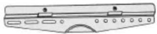
4
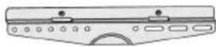
5
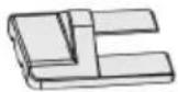
678910


11121314


15161718


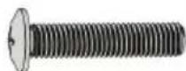
19202122


232425

2
flowchart
graph LR
    A["External Component"] --> B["Internal Component"]
    B --> C["Internal Rotation"]
    C --> D["Internal Rotation"]
    D --> E["Internal Structure"]
3
4
5

natural_image
Technical illustration of a mechanical assembly with two views showing internal components and directional arrows (no text or symbols)6

7

8

9

10

natural_image
Technical illustration of a mechanical assembly with two views showing internal components and rotational motion (no text or symbols)11
12
natural_image
Technical line drawing of a mechanical assembly with a magnified inset showing internal components (no text or symbols)13

SÄKERHETSANVISNINGAR
- Kabelklämma x1 l
- Skruv M4 x1 J
- Skruv M6 x 12 x4 K
- Skruv M6 x 25 x4 L
- Bricka D6 x4 M
- Insexnyckel x1 N
- Skruv M5 x 14 x4 M-A
- Skruv M6 x 14 x4 M-B
- Skruv M8 x 20 x4 M-C
- Skruv M6 x 30 x4 M-D
- Skruv M8 x 30 x4 M-E
- Bricka x4 M-F
- Distans x8 M-G
- Distans x4 M-H
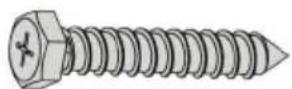
- Skruv ST6,3 x 55 x4 W-A
- Plugg x4 W-B
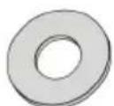
- Bricka D6 x4 W-C
BILD 1
MONTERING
DEMONTERING AV VESA-FÄSTE
- Read all the instructions before installation.
- Contact your dealer if you have any questions.
- The product must only be used for its intended purpose and in accordance with these instructions.
- Incorrect installation can result in the risk of personal injury and/or material damage.
- Check that the wall can support the total weight of the bracket and the television.
- At least two persons are needed, or use a mechanical lifting device, to lift and position the equipment.
- Tighten the screws firmly, but do not overtighten.
- The product is only intended for indoor use. Using it outdoors can result in personal injury and/or material damage.
WARNING!
Do not exceed the permitted load (max 35 kg) – risk of personal injury and/or material damage.
TECHNICAL DATA
| Max load | 35 kg |
| Weight | 6.34 kg |
| TV size | 37-70" |
DESCRIPTION
- Swivel bracket x1 A
- Mounting template x1 B
- Horizontal stay x2 C
- Right bracket, vertical x1 D
- Left bracket, vertical x1 E
- Decoration x2 F
-
Decoration x1 G
-
Cable strain relief x1 H
- Cable clip x1 l
- Screw M4 x1 J
- Screw M6 x 12 x4 K
- Screw M6 x 25 x4 L
- Washer D6 x4 M
- Hex key x1 N
- Screw M5 x 14 x4 M-A
- Screw M6 x 14 x4 M-B
- Screw M8 x 20 x4 M-C
- Screw M6 x 30 x4 M-D
- Screw M8 x 30 x4 M-E
- Washer x4 M-F
- Spacer x8 M-G
- Spacer x4 M-H
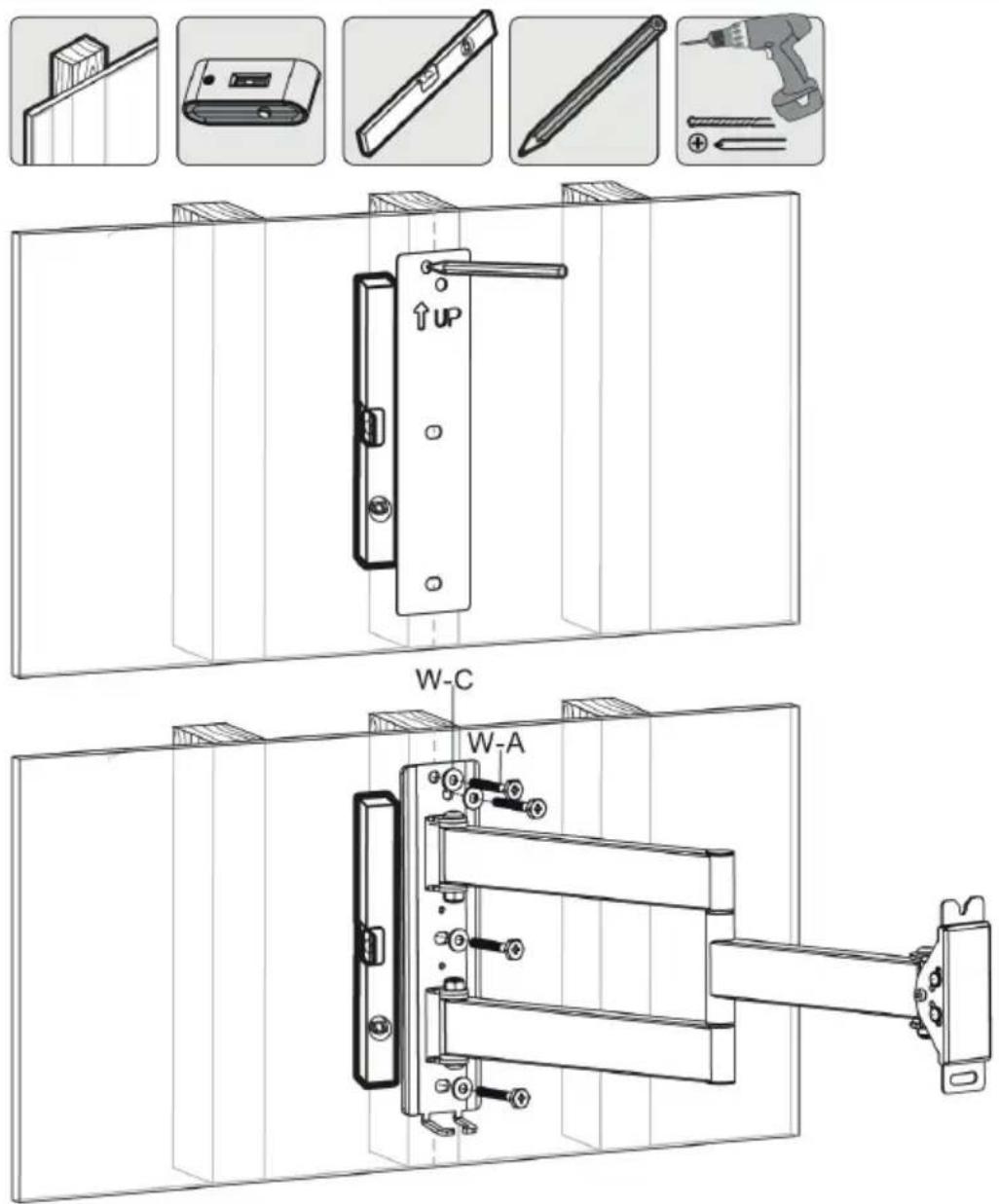
- Screw ST6.3 x 55 x4 W-A
- Plug x4 W-B
- Washer D6 x4 W-C
FIG. 1
ASSEMBLY
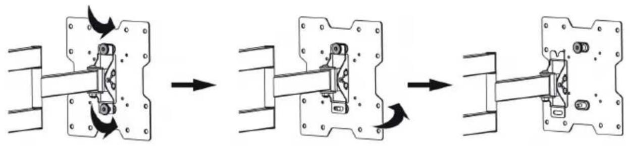
REMOVAL OF VESA MOUNT
- Loosen the top thumb screw.
- Unscrew the bottom thumb screw all the way.
- Lift up the adapter plate and remove it from the swivel bracket.
FIG. 2
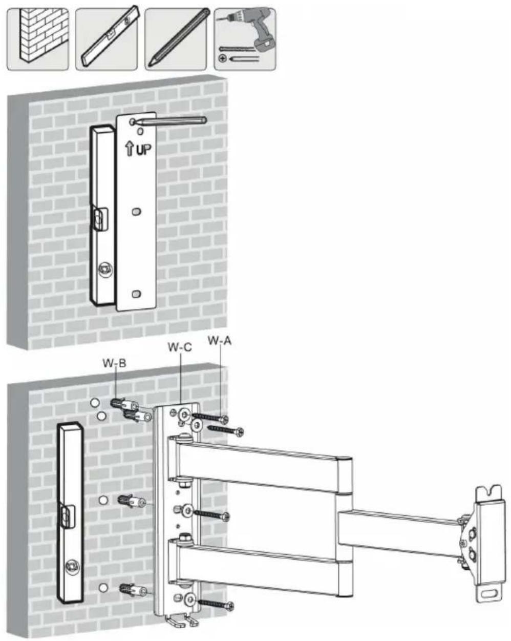
MOUNTING ON WOODEN STUDS
NOTE:
Make sure that the arrow on the mounting template points upwards.
-
Mark out the position of the holes with the mounting template.
-
Predrill the holes.
- Screw on the swivel bracket. Use screws and washers.
FIG. 3
IMPORTANT:
- Fasten the screws in the middle of the studs.
- Make sure to use suitable parts for the installation.
- Check that the wall can support the total weight of the bracket and the television.
- Check at least every 3 months that the bracket is correctly mounted.
MOUNTING ON CONCRETE/BRICK WALL
NOTE:
Make sure that the arrow on the mounting template points upwards.
- Mark out the position of the holes with the mounting template.
- Predrill the holes.
- Put plugs in the predrilled holes.
- Screw on the swivel bracket. Use screws and washers.
FIG. 4
IMPORTANT:
- Check that the concrete is at least 35 mm thick to accommodate the concrete anchors. Do not drill into mortar joints. Drill into the bricks or concrete blocks, preferably at least 25 mm from the edge.
- Make sure to use suitable parts for the installation.
- Check that the wall can support the total weight of the bracket and the television.
- Check at least every 3 months that the bracket is correctly mounted.
FITTING THE DECORATIONS
FIG. 5
FITTING THE ADAPTER PLATE
- Put the horizontal stays in the left and right bracket.
- Fasten the adapter plate on the horizontal stays.
FIG. 6
MOUNTING OF BRACKETS ON TELEVISION
Mounting without spacers
- Put the vertical brackets on the back of the television, as close to the middle as possible.
- Screw the brackets on the television.
FIG. 7
IMPORTANT:
Tighten the screws firmly, but do not overtighten.
Mounting with spacers
- Use suitable screws, washers and spacers for the actual television.
- Put the vertical brackets on the back of the television.
- Screw the brackets on the television.
FIG. 8
IMPORTANT:
Tighten the screws firmly, but do not overtighten.
MOUNTING OF TELEVISION
NOTE:
Two persons are needed to mount the television.
- Make sure the top thumb screw is unscrewed about 4 mm.
FIG. 9
-
Mount the television on the swivel bracket. Make sure the thumb screw fits in the intended slot on the bracket.
-
Screw in the bottom thumb screw.
-
Tighten both thumb screws.
FIG. 10
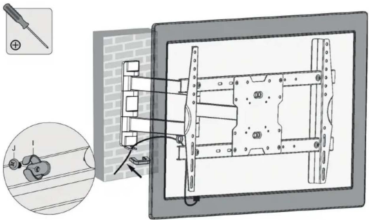
CABLE ROUTING
-
Fit the cable clip on the swivel bracket.
-
Connect the cables to the television.
-
Route the cables through the cable clip.
-
Put the cable through the integrated cable retainer on the swivel bracket.
FIG. 11
NOTE:
Make sure the cables are not overstretched. Stretched cables prevent the bracket moving.
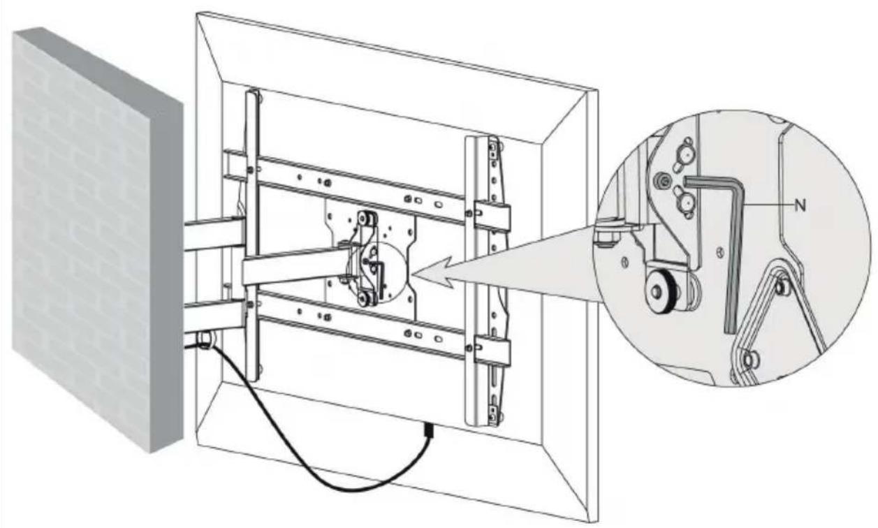
ADJUSTING THE BRACKET ANGLE
Undo or tighten the set screw with a hex key. Have someone hold the television while doing this.
FIG. 12
- SE VÄGGFÄSTE
- SÄKERHETSANVISNINGAR
- BILD 1
- MONTERING
- DEMONTERING AV VESA-FÄSTE
- WARNING!
- DESCRIPTION
- ASSEMBLY
- REMOVAL OF VESA MOUNT
- MOUNTING ON WOODEN STUDS
- NOTE:
- Make sure that the arrow on the mounting template points upwards.
- 3
- IMPORTANT:
- MOUNTING ON CONCRETE/BRICK WALL
- 4
- FITTING THE DECORATIONS
- 5
- FITTING THE ADAPTER PLATE
- 6
- MOUNTING OF BRACKETS ON TELEVISION
- Mounting without spacers
- 7
- Tighten the screws firmly, but do not overtighten.
- Mounting with spacers
- 8
- MOUNTING OF TELEVISION
- Two persons are needed to mount the television.
- 9
- 10
- CABLE ROUTING
- 11
- Make sure the cables are not overstretched. Stretched cables prevent the bracket moving.
- ADJUSTING THE BRACKET ANGLE
- 12
Brand : Marquant
Model : 929-081
Category : Wall mount