L40PFW17E - Fan Logik - Free user manual and instructions
Find the device manual for free L40PFW17E Logik in PDF.
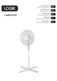


| Product Type | Pedestal Fan |
| Brand | Logik |
| Model | L40PFW17E |
| Rated Voltage | 220-240 V |
| Rated Frequency | 50 Hz |
| Input Power | 40 W |
| Max Airflow Rate | 59 m³/min |
| Fan Power Input | 33 W |
| Service Value | 1.78 (m³/min)/W |
| Standby Power Consumption | 0.0 W |
| Seasonal Electricity Consumption | 10.7 kWh/a |
| Sound Power Level | 54 dB(A) |
| Max Air Velocity | 2.8 m/s |
| Number of Speeds | 3 (off, low, medium, high) |
| Oscillation | Yes (push/pull control) |
| Height Adjustment | Yes (telescopic stand with locking collar) |
| Control Type | Push button for speed, push/pull for oscillation |
| Power Cord Length | Approx. 1.5 m |
| Color | White |
| Material | Plastic and metal grille |
| Included Accessories | Motor unit, front guard, rear guard, 2 feet, stand, fan blade, securing nut, spinner, instruction manual |
| Assembly Required | Yes |
| Cleaning Instructions | Unplug, wipe with damp cloth; do not immerse or use chemicals |
Frequently Asked Questions - L40PFW17E Logik
User questions about L40PFW17E Logik
0 question about this device. Answer the ones you know or ask your own.
Ask a new question about this device
Download the instructions for your Fan in PDF format for free! Find your manual L40PFW17E - Logik and take your electronic device back in hand. On this page are published all the documents necessary for the use of your device. L40PFW17E by Logik.
USER MANUAL L40PFW17E Logik
Contents
Safety Warnings....4
Unpacking....9
Assembling Your Fan....10
Product Overview....13
How to Use Your Fan....14
Cleaning 14
Hints and Tips....14
Specifications....15
Thank you for purchasing your new product.
We recommend that you spend some time reading this instruction manual in order that you fully understand all the operational features it offers. You will also find some hints and tips to help you resolve any issues.
Read all the safety instructions carefully before use and keep this instruction manual for future reference.
Unpacking
Remove all items from the packaging. Retain the packaging. If you dispose of it please do so according to local regulations.
The following items are included:
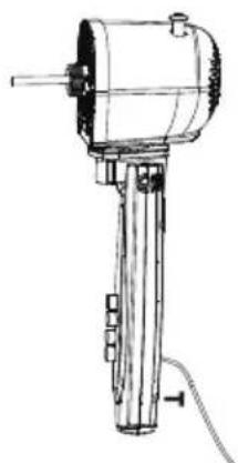
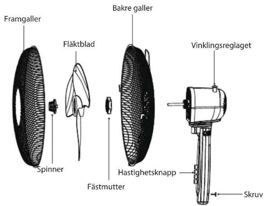
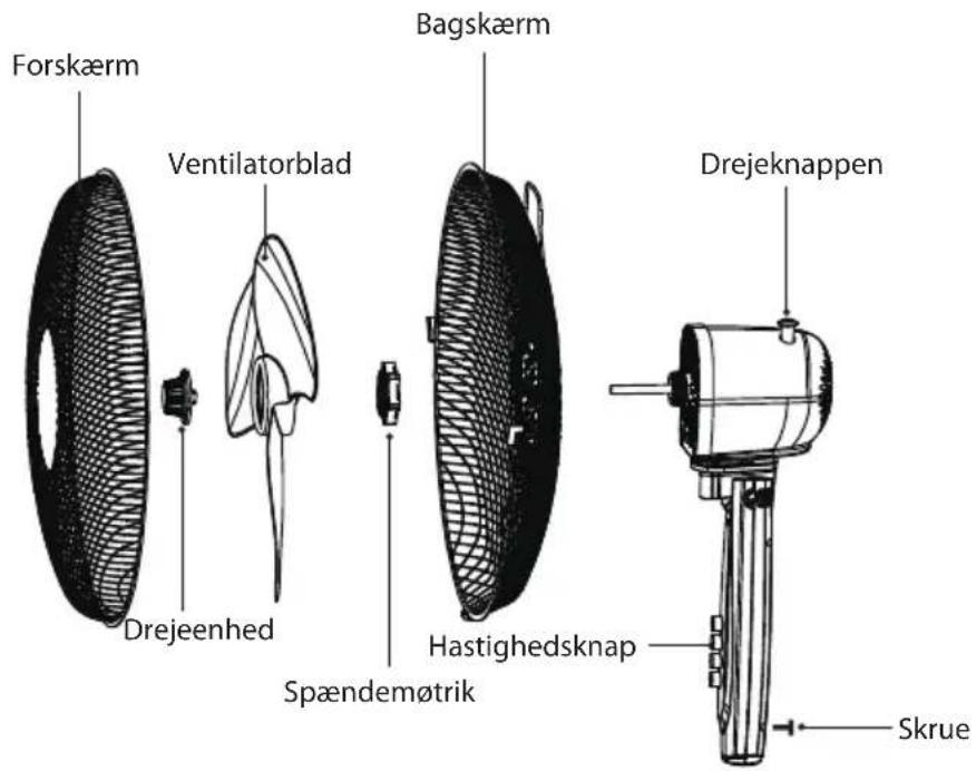
Motor Unit with Screw and Power Cord
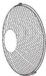
Front Guard (with Screw and Nut)
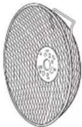
Rear Guard
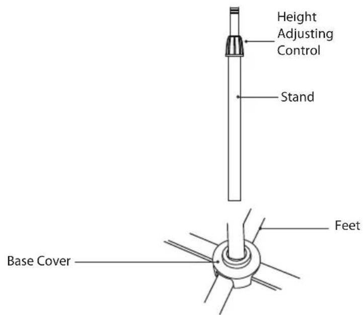
Base Cover
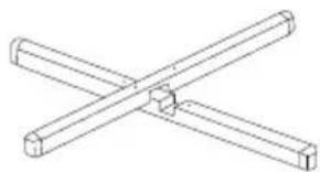
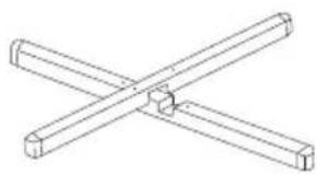
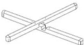
Feet x 2 with Screws and Washers
Stand
Fan Blade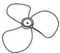
Securing Nut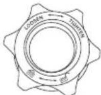
Spinner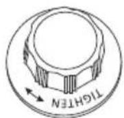
Instruction Manual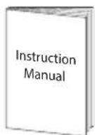
Assembling Your Fan

- Avoid using your fan in hazardous areas.
- Do not use your fan if it has not been fully assembled. Make sure that the screw(s) that hold the base parts and the main unit together is(are) tightened securely.
- Do not connect the unit to the mains until the assembly is finished. Use a Philips style screwdriver to assemble and secure.
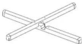
- Unscrew the screws and washers from the feet.
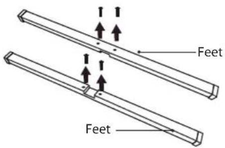
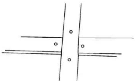
- Fix the 2 feet on each other.
- Insert the stand onto the base, then tighten it with the screws and washers.
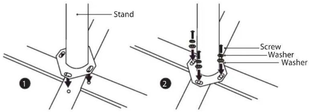
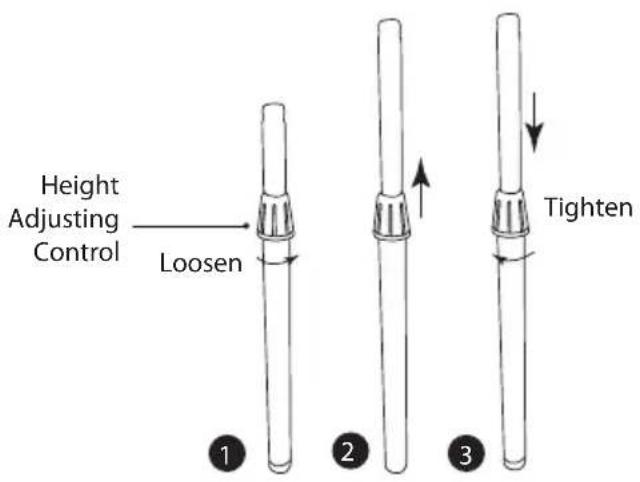
- Adjust the height of the stand.
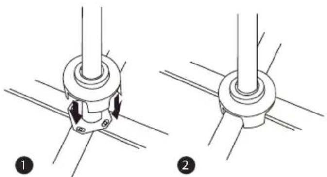
- Cover the screws with the base cover.
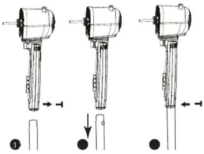
- Detach the screw from the motor unit, attach the motor unit onto the stand then tighten it with the screw.
- Attach the front and rear guards.
![graph TD A["Front Guard"] --> B["Spinner"] B --> C["Securing Nut"] C --> D["Rear Guard"] style A fill:#f9f,stroke:#333 style D fill:#bbf,stroke:#333](/content/2026/05/871072/images/93294720bc7b67df6167c45907cd4498778d53490f17e71d10bf954b730439af.jpg)
8.
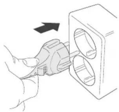
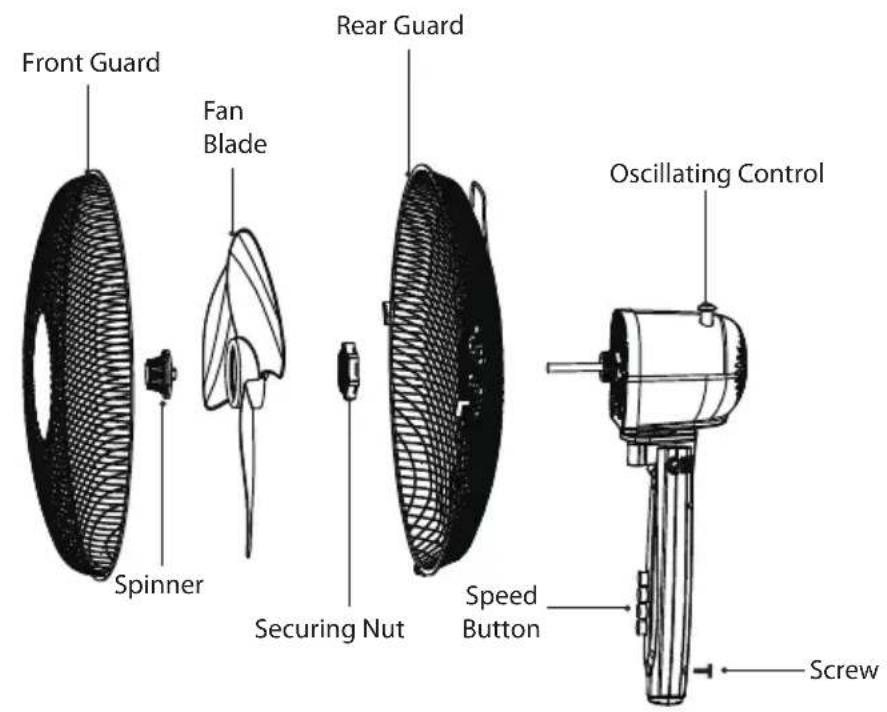
- Press the Speed BUTTON for the required fan speed. The following settings are available:
0 - The Fan is switched Off
1 - The Fan operates at the lowest speed 2 - The Fan operates at the medium speed 3 - The Fan operates at the highest speed
- To make the fan head oscillate, push the Oscillating Control down. To stop the oscillation, pull the Oscillating Control up. The head of the fan can be adjusted up or down.
- The height of the fan can be adjusted up or down. To do this, loosen the Height Adjusting Control, pull on the Stand to the desired height, then tighten the Height Adjusting Control.
Cleaning
Unplug the unit from the mains socket.
Use a slightly damp cloth to wipe the outer body of the unit. Never completely cover the unit with water or use chemicals or detergents as they could damage the unit in some way.
Hints and Tips
| Problem Solution | |
| The force of air coming from the unit is weak. | Adjust the speed up to a higher setting. |
| The unit does not work. Check that the plug | is connected correctly and that the unit is turned on at the mains supply. |
| Other abnormal conditions. Disconnect the | fan from the wall and consult a repair specialist. |
Specifications
| Model L40PFW17E | |
| Rated Voltage 220-240 V | |
| Rated Frequency 50 Hz | |
| Input Power 40 W | |
| Maximum Fan Flow Rate (F) 59 m | 3 /min |
| Fan Power Input (P) 33 W | |
| Service Value (SV) 1.78 (m) | 3 /min)/W |
| Standby Power Consumption (Psb) 0.0 W | |
| Seasonal Electricity Consumption (Q) 10.7 kWh/a | |
| Fan Sound Power Level (Lwa) 54 dB(A) | |
| Maximum Air Velocity (c) 2.8 meters/sec | |
| Measurement Standard for Service Value | IEC 60879:1986 (corr.1992) |
Features and specifications are subject to change without prior notice.
Thank you
for purchasing our new product.
NO
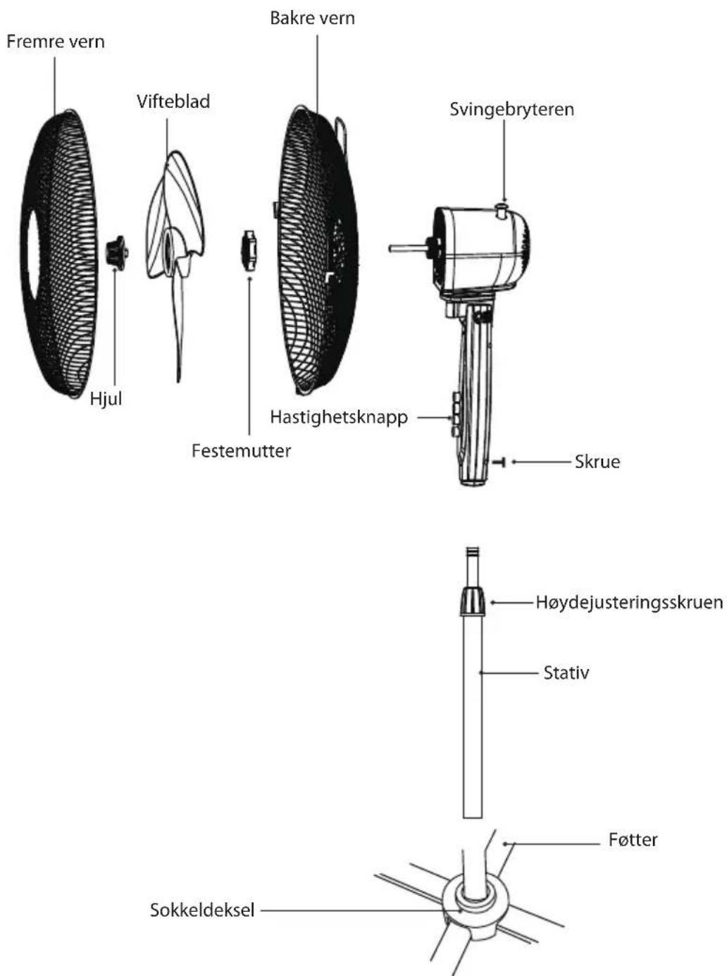
Rear grille
Base housing
SE
Top cover
Base cover
FI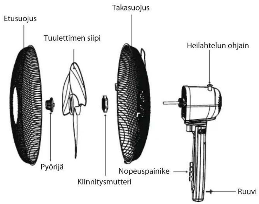
Front fender (with screws and nuts)
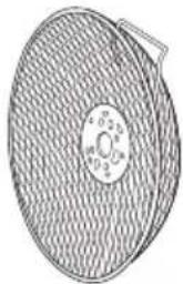
Rear fender
Foot cover
The symbol on the product or its packaging indicates that this product must not be disposed of with your other household waste. Instead, it is your responsibility to dispose of your waste equipment by handing it over to a designated collection point for the recycling of waste electrical and electronic equipment. The separate
collection and recycling of your waste equipment at the time of disposal will help conserve natural resources and ensure that it is recycled in a manner that protects human health and the environment.
For more information about where you can drop off your waste for recycling, please contact your local authority, or where you purchased your product.
NO
Brand : Logik
Model : L40PFW17E
Category : Fan