Bonn Germany Concept 2.2 - Fitness Equipment Joy Sport - Free user manual and instructions
Find the device manual for free Bonn Germany Concept 2.2 Joy Sport in PDF.


| Product Type | Magnetic resistance rowing machine |
| Brand / Model | Joy Sport / Bonn Germany Concept 2.2 |
| Intended Use | Home fitness equipment |
| Maximum User Weight | 150 kg (330 lbs) |
| Resistance System | Air and magnetic (Air Mag. system) |
| Resistance Levels | Manual adjustment via +/- keys on monitor |
| Monitor Display | LCD with scan, time, distance, calories, strokes, SPM, RPM, speed, pulse, power, 500m split, ODO |
| Programs | 8 programs: Manual (P1), 5 preset (P2-P6), 2 Heart Rate Control (P7-P8 60% and 85% max HR) |
| Heart Rate Monitoring | Wireless chest strap (included) |
| Power Supply | AC adaptor (included, 116), plug into wall outlet |
| Dimensions (approx.) | Seat track length ~120 cm; overall length ~200 cm; width ~50 cm; height ~70 cm |
| Weight (approx.) | ~40 kg (88 lbs) |
| Seat | Sliding seat on carriage with wheels, adjustable stoppers |
| Foot Pedals | Adjustable with straps and velcro |
| Handlebar | Adjustable, folds for storage |
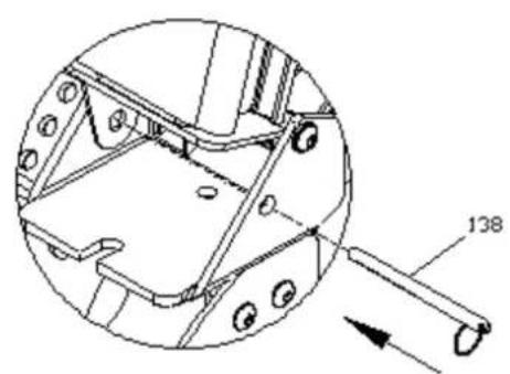
| Storage | Upright storage with lock pin (138); fold seat forward |
| Frame Material | Steel tube with painted finish |
| Transport Wheels | Front stabilizer with wheels |
| Safety Precautions | Consult physician before use; keep children/pets away; warm up/cool down; max weight 150 kg; inspect before use |
| Maintenance | Check and tighten bolts regularly; clean with damp cloth; keep away from moisture |
| Spare Parts Availability | Full parts list in manual; contact manufacturer for replacements |
| Included Accessories | Wireless chest strap, AC adaptor, allen wrench, universal wrench, assembly hardware |
| Warranty | Not specified; home use only |
Frequently Asked Questions - Bonn Germany Concept 2.2 Joy Sport
User questions about Bonn Germany Concept 2.2 Joy Sport
0 question about this device. Answer the ones you know or ask your own.
Ask a new question about this device
Download the instructions for your Fitness Equipment in PDF format for free! Find your manual Bonn Germany Concept 2.2 - Joy Sport and take your electronic device back in hand. On this page are published all the documents necessary for the use of your device. Bonn Germany Concept 2.2 by Joy Sport.
USER MANUAL Bonn Germany Concept 2.2 Joy Sport
Stap 3
Stap 5
Stap 6
De roeier opbergen.


Snel START:
H.R.C. (Heart Rate Control):
CAUTION: Weight on this product should not exceed 150kgs.
CAUTION: Exercise of a strenuous nature, as is customarily done on this equipment,
should not be undertaken without first consulting a physician. No specific health claims
are made or implied as they relate to the equipment. Measurements made by the equipment
are believed to be accurate, but only the measurements of your physician should be relied upon.
IMPORTANT: Read all instructions carefully before using this product. Retain this owner's manual for future reference.
| Table of Contents | |
| 2 | Safety Precautions |
| 3 | Hardware Packing List |
| 4 | Pre-assembly Check List |
| 5~10 | Assembly |
| 11~13 | Monitor instruction |
| 14-15 | Parts List |
| 16 | Exploded Drawing |
SAFETY PRECAUTIONS
Thank you for purchasing our product. Even though we go to great efforts to ensure the quality of each product we produce, occasional errors and/or omissions do occur. In any event should you find this product to have either a defective or a missing part please contact us for a replacement.
This product has been designed for home use only. Product liability and guarantee conditions will not be applicable to products being subjected to professional use or products being used in a gym centre.
This exercise equipment was designed and built for optimum safety. However, certain precautions apply whenever you operate a piece of exercise equipment. Be sure to read the entire manual before assembly and operation of this machine. Also, please note the following safety precautions:
- Read the OWNER'S OPERATING MANUAL and all accompanying literature and follow it carefully before using your elliptical.
- If dizziness, nausea, chest pains, or any other abnormal symptoms are experienced while using this equipment, STOP the workout at once. CONSULT A PHYSICIAN IMMEDIATELY.
- Inspect your exercise equipment prior to exercising to ensure that all nuts and bolts are fully tightened before each use.
- The elliptical must be regularly checked for signs of wear and damage. Any part found defective, the part must be replaced with new spare part from the manufacturer.
- Fitness equipment must always be installed on a flat surface, do not place the unit on a loose rug or uneven surface. It is recommended to use an equipment mat to prevent the unit from moving while it is being used, which could possibly scratch or damage the surface of your floor.
-
No changes must be made which might compromise the safety of the equipment.
-
It is recommended to have a minimum of 2' safe clearance around the exercise equipment while in use.
-
Keep children and pets away from this equipment at all times while exercising.
-
Warm up 5 to 10 minutes before each workout and cool down 5 to 10 minutes afterward. This allows your heart rate to gradually increase and decrease and will help prevent you from straining muscles.
-
Never hold your breath while exercising. Breathing should remain at a normal rate in conjunction with the level of exercise being performed
-
Always wear suitable clothing and footwear while exercising. Do not wear loose fitting clothing that could become entangled with the moving parts of your elliptical.
-
Care must be taken when lifting or moving the equipment, so as not to injure your back. Always use proper lifting techniques
-
User weight should not exceed 150 kgs.
-
Tie all long hair back and remove all personal jewelry before exercising.
-
After eating, allow 1-2 hours before exercising as this will help to prevent muscle strain.
-
Injuries may result from incorrect or excessive training and using the equipment other than as directed or recommended by your doctor.
HARDWARE PACKING LIST
| PART | DESCRIPTION | Q'TY | SKETCH | |
| 21 Seat track end cap 1 | 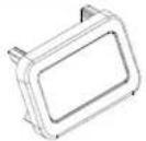 |  | ||
| 23 Spacer 1 | ||||
| 24 Knob 1 |  |  | ||
| 26 Flat washer M8 6 | ||||
| 29 Cap nut M10 4 |  |  | ||
| 76 Nylon nut M10 | 6 | |||
| 77 Flat washer M10 12 |  |  | ||
| 104 Spring washer M8 4 | ||||
| 110 Allen head bolt M8* 25mm 2 |  |  | ||
| 107 M10X20 Allen head bolt 2 | ||||
| 114 Spring washer M10 | 12 |  |  | |
| 117 Allen head bolt M8* 15mm 4 | ||||
| 122 Nut M8 | 1 |  | 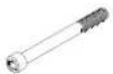 | |
| 123 Hex head bolt M8* 85mm | 1 | |||
| 22 Seat Carriage Stopper | 2 |  | 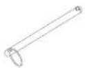 | |
| 138 Pin | 1 | |||
| 111 M10X25 Allen head bolt | 6 | [SZHK] | ||
| Allen wrench | 1 |  |  | |
| Universal wrench | 1 | |||
PRE-ASSEMBLY CHECK LIST

| PART NO. DESCRIPTION QTY | ||
| 1 | Front frame with air mag. drive system set | 1 |
| 6/28(R/L)/124 | Front stabilizer w/transportation wheels, anti-slippery pads | 1 |
| 5/20(R(L)/98 | Rear stabilizer w/end caps, level knobs | 1 |
| 12/7/113(R/L)/125 | Foot plate w/foot pedal, pedal straps, elastic velcro straps | 1P |
| 4/3/120 | Seat track w/connected bracket, count sensor wire | 1 |
| 13/8/17 | Seat w/carriage wheel set | 1 |
| 84/83 | Monitor w/four screws | 1 |
| 2/105/122/27 | U support bracket w/knob, spacer, level knob | 1 |
| Wireless chest belt set | 1 | |
| 116 | Adaptor with cable | 1 |
ASSEMBLY INSTRUCTION
GENERAL
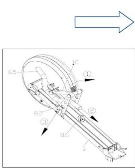
REMOVE ALL THE PARTS OF YOUR ROWER FROM THE CARTON AND PLACE THEM ON THE FLOOR CAREFULLY. ASSEMBLING YOUR ROWER IS SIMPLE. FOLLOW THESE INSTRUCTIONS
1) Secure with knob (105) & washer (26) on monitor support bracket (9) and front main frame (1).
2) Cut the zip tie (82) between two monitor support bracket (9).
3) Cut the zip tie (82) between handlebar (65) and monitor support bracket (9).
4) Pull and slide the handlebar (65) and pass through the monitor support bracket (9) and monitor bracket (11) carefully as shown.
5) Rotate the handlebar (65) to right 90° and rest onto the handlebar stand (86) in position.
NOTE: Please follow the following step to assemble handlebar and avoid the chain to
drop off from the pivot shaft.
Use left hand to hold the chain (66) which is located on gear of pivot shaft and right hand grips handlebar (65) through the monitor support bracket (9) & monitor bracket (11),
and place handlebar (65) on stand (86).
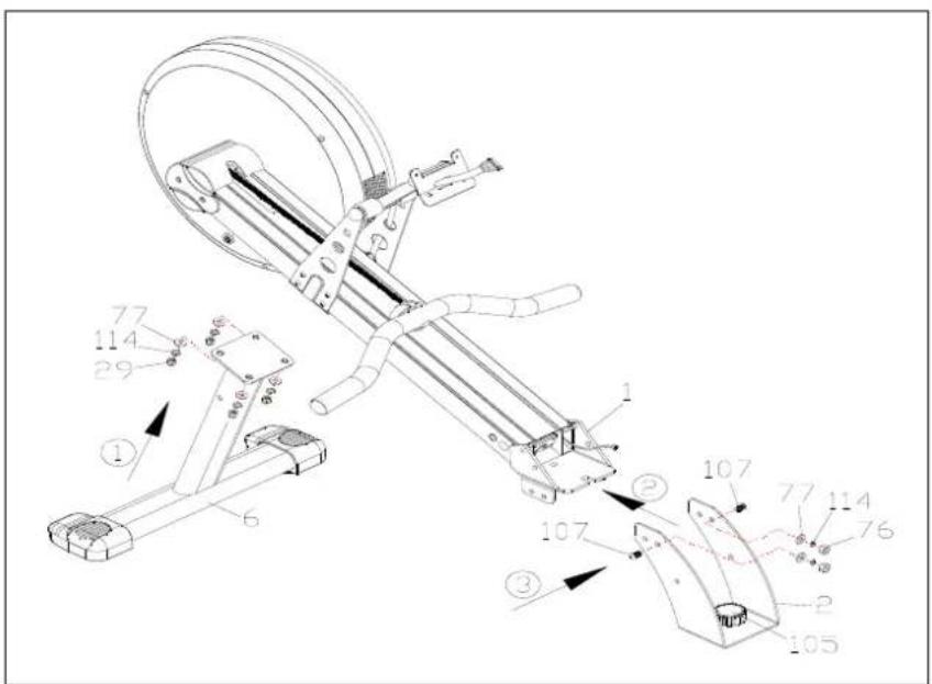
6) Put the top welded bracket of front stabilizer (6) with two wheel caps (28R/L) to bottom four screw holes of front main frame (1) and tighten with four cap nuts (29), four spring washers (114) and four flat washers (77).
7) Attach "U" support bracket (2) to the end "U" welded bracket of front main frame (1) and tighten with two allen head bolts (107), two flat washers (77), two spring washers (114) and two nylon nuts (76).
NOTE: After finish whole product assembly, you can screw the pre-assembled level knob
(27) to adjust the whole product balance.
STEP 2
1) Attach the three welded “Γ” shape bracket of right metal foot plate (7R) with plastic foot pedal (12), velcro straps (113) to the right 3 screw holes of main frame (1) and support bracket (2) and secure with three allen head bolts (111), three spring washers (114), three flat washers (77) and two nylon locknuts (76) per drawing.
2) Do the same step to assemble left metal foot plate (7L), plastic foot pedal (12) and velcro Straps (113) with the left 3 screw holes of main frame (1) and support bracket (2).
NOTE: Please move the slot of foot pedal (12) of pre-assembled metal foot plate (7R/7L), foot pedal (12) velcro straps (113) to adjust the user's foot.

STEP 3
1) Slide the seat (13) with seat carriage set (8) into the rower seat track (4) which direction is from end of seat track (4).
2) Put one bolt (123) with one stopper (22) through the two side hole of rower seat track (4) and tighten with another stopper (22) and nut (122).
3) Put the end cap (21) into end of seat track (4).

STEP 4
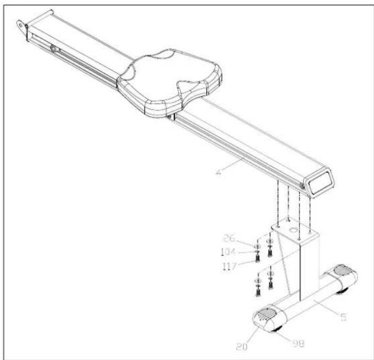
1) Attach the welded bracket of rear stabilizer (5) with two end cap set (20/98) to the bottom four screw hole of end seat track (4) and tighten with four allen head bolts (117), four spring washers (104) and four flat washers (26).
NOTE: After finish whole product assembly, you can screw the pre-assembled level knob (98) of rear stabilizer (5) to adjust the whole product balance.
STEP 5
1) Attach the socket of count sensor (120) of seat track (4) to the plug of count sensor wire (129) of front main frame (1) per the following drawing.
2) Put the front welded thread pole of seat track (4) to the "C" type welded bracket of main frame (1) and tighten with two allen head bolts (110) and two flat washers (26) per the drawing.
3) Put the level knob (24) with big spacer (23) to the bottom screw hole of front end seat track (4) and tighten well the level knob (24) to touch the "C" welded bracket per drawing.
■ NOTE: Avoid punching all cables and wires.

STEP 6
1) Remove the pre-assembled four screws (83) from back of monitor (84).
2) Insert plug of system wire cable (102) to the socket of monitor (84).
3) Attach monitor (84) to the top adjustable monitor bracket (11) and tighten with previously removed four screws (83) again.
NOTE: The manufacturer has pre-assembled the adjustable monitor bracket (11) with monitor support bracket (9) on front main frame (1).

STEP 7
■ Insert the plug of the adaptor (116) into the socket (112) of power supply cable as shown.
■ Plug the two pin of adaptor (116) into the wall power supply.

Now the rower is finished completely.

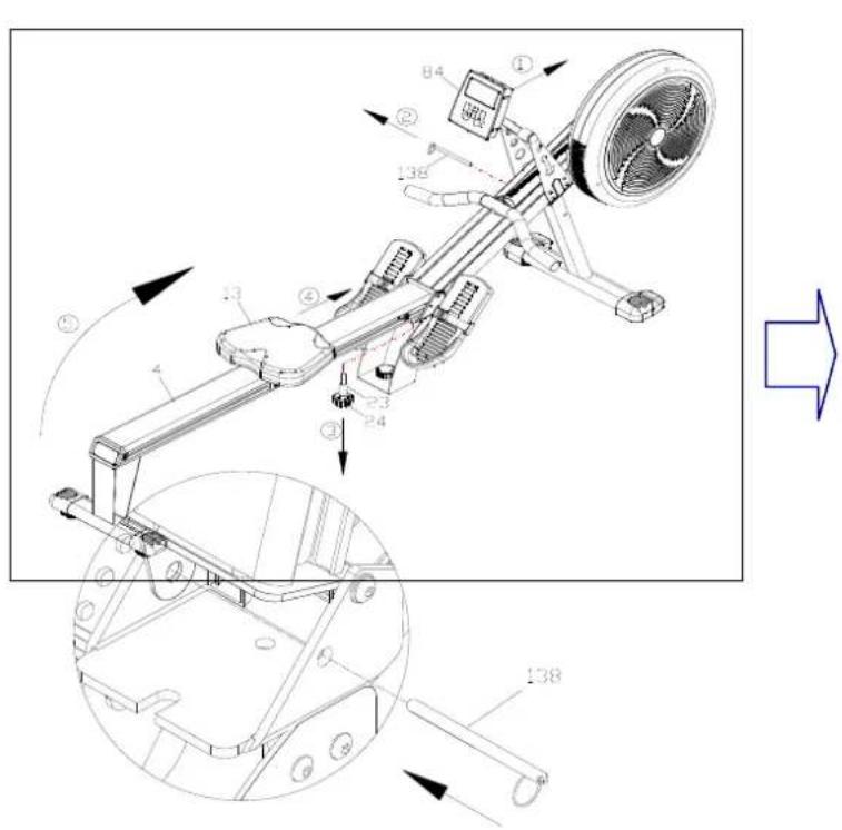
HOW TO STORE YOUR ROWER
1) Loosen knob (24) with spacer (23) to leave 20mm distance and slide seat (13) to the front end of seat track (4).
2) Push the two monitor support bracket (11) with monitor (84) forward a little bit to front main frame (1).
3) Lift up seat track (4) to welded U bracket of front main frame (1) and insert the pin (138) to thread the two side hole of "U" shape bracket of from main frame (1) and ear of front end connected bracket (3) of seat track (4).

MONITOR INSTRUCTION

QUI CK START:
- Press the "display mode"
button to activate the computer console.
- Begin rowing.
- Adjust the resistance level with the "+" / "-" key
- The values of time, distance, calories, count, will start counting upwards.
DISPLAY AND FEEDBACK:
| AGE | The user age has been set. |
| PROGRAM | The number of the selected pre-set program (1~8). |
| min. iiiiiiii max. | Displays the resistance level in manual mode. |
| THR | Target heart rate frequency has been set. |
| SCAN | Automatically scans through the feedback modes. Each being displayed for 5 seconds. |
| PULSE | Current heart rate in beats per minute (bpm) (Only displayed when the transmitter chest strap is used.) |
| CAL | Approximate calories burned this session (for comparison only, not to be used for medical purposes); default counts up from zero, but counts down if a target has been set. |
| SPM | The strokes per minute (S.P.M) you are rowing at. |
| RPM | The revolutions per minutes (RPM) you are rowing at, |
| DST | Distance travelled this session; default counts up from zero, but counts down if a target has been set. |
| SPD | The current speed you are rowing at, in KM/H. |
| ODO | Total distance travelled since last battery changed. |
| TIME | Time exercised this session; default counts up from zero, but counts down if a target has been set. |
| COUNT | Stroke exercised this session; default counts up from zero, but counts down if a target has been set |
| 500M | Expected exercise time for 500 meters travelled. |
| POWER | The force of each rowing stroke. |

Screen Display
BUTTON FUNCTIONS:
| Button Pre-workout During workout | ||
| Display Mode | Switch different mode values Select display mode | |
| Program Press repeatedly to select a program (p1~p8) | ||
| set Confirm current target values setting | ||
| reset | Reset current setting value, press & hold total reset | |
| + | Increase values setting in “target setting” mode Increase the resistance level | |
| - | Decrease values setting in “target setting” mode | Decrease the resistance level |
USING WORKOUT PROGRAMS:
When you turn the rower on it will enter the main display mode, waiting for your to select a program and begin your workout.
MANUAL:
In manual mode, the user is free to adjust the resistance level at any point throughout the workout.
- Press "program" button to choose your program (p1).
- Press "set" button to confirm the "manual" selection.
- Start rowing to begin your workout.
NOTE: You can also add to your program targets based on time, distance, calories, stroke or pulse rate. To do this, see the “Target Program” instruction below.
PROGRAM:
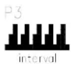
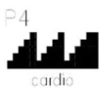
There are 5 pre-set programs available for you to choose from. The resistance level adjusts automatically throughout the program.
- Press "program" button to choose your program (P2\~P6).
- Press "set" button to confirm your selection
- Press "display mode" button to enter the "time" mode.
- The value of "00:00" will be flashing in the "time" window
- Press “+” or “-” button to set your workout time
- Press 'set" to confirm your setting
- Start rowing to begin your workout
NOTE: 1) You can change the resistance level at any point during the workout and the rest of
segments will be
adjusted by scale automatically
2) You can also add to your program targets based on time, distance, calories, stroke or pulse rate. To do this, see the "Target Program" instruction below
3) Each program is made up of 16 segments and the length of each segment will on the time you set for your workout.
H.R.C. (Heart Rate Control):
HRC program works by automatically adjusting the resistance to keep you working out at your target heart rate. To do this the console will need your pulse reading throughout the exercise, which it gets from you wearing a chest strap transmitter.
If your heart rate is too high the resistance is decreased.
If your heart rate is too low the resistance is increased
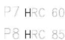
This console features 2 heart rate control programs:.
. 60% - Target to operate at 60% of your maximum heart rate to lose weight.
. 85% - Target to operate at 85% of your maximum heart rate to improve your stamina.
- Press & hold" display mode' button for 5 seconds to enter the "age" mode
- Press "+" or "-" button to set your age
- Press "display mode" to confirm your setting
- Press "program" button to choose your program (p7 - 60% Max. HR/p8 - 85% Max. HR)
- Press "set" button to confirm your selection
- The value of "THR" will be flashing in the "pulse" window
- Press "set" to confirm your target heart rate setting
- Start rowing to begin your workout
NOTE: You can also add to your program targets based on time, distance, calories or stroke. To do this, see the "Target Program" instruction below
TARGET PROGRAM:
You can choose to workout by setting a target based on pulse rate, calories burned, distance travelled, time or the strokes rowed you want to achieve.
When you reach your target the rower will sound a short alarm.
Set to your desired program as described previously, but before pressing "set" to begin your exercise.
- The value of "0" will be flashing in the "pulse' window
- Press "+" or "-" button to set your Target Pulse Rate.
- Press "set" to confirm your setting
- The value of "0" will be flashing in the "calories" window
- Press “+” or “-” button to set your Target Calories
- Press "set" to confirm your setting
- The value of "0" will be flashing in the "distance" window
- Press "+" or "-" button to set your Target Distance
- Press "set" to confirm your setting
- The value of "00:00" will be flashing in the "time" window
- Press "+" or "-" button to set your Target Time
- Press "set" to confirm your setting
- The value of "0" will be flashing in the "count" window
- Press “+” or “-” button to set your Target Stroke
- Press "set" to confirm your setting
- Start rowing to begin your workout
NOTE: You only have to set one of the targets described above, and once done you can press "set" to go straight into your workout, however, if you set multiple targets the workout will end when the first target is reached.




PARTS LIST
| NO. | DESCRIPTION | Q'TY (PCS) | NO. | DESCRIPTION | Q'TY (PCS) |
| 1 | MAIN FRAME | 1 | 36 | BUSHING | 3 |
| 2 | MAIN FRAME SUPPORT BRACKET | 1 | 37 | SLEEVE | 2 |
| 3 | CONNECTED BRACKET | 1 | 38 | ELASTIC CORD | 1 |
| 4 | ROWER SEAT TRACK | 1 | 39 | M8*35mm ALLEN HEAD BOLT | 1 |
| 5 | REAR STABILIZER | 1 | 40 | CHAIN GUIDE PULLEY | 1 |
| 6 | FRONT STABILIZER | 1 | 41 | SHORT ELASTIC TUBE | 1 |
| 7 | FOOT PLATE | 1p | 42 | FLAT WASHER | 4 |
| 8 | SEAT CARRIAGE BRACKET | 1 | 43 | CLIP | 2 |
| 9 | COMPUTER SUUPORT BRACKET | 2 | 44 | BUSHING | 2 |
| 10 | BRACKET | 1 | 45 | ELASTIC CORD GUIDE PULLEY | 3 |
| 11 | MONITOR BRACKET | 1 | 46 | PIN | 1 |
| 12 | FOOT PEDAL | 2 | 47 | U BRACKET | 1 |
| 13 | SEAT | 1 | 48 | M8*95MM ALLEN HEAD BOLT | 1 |
| 14 | M6*15mm ACROSS HEAD SCREW | 4 | 49 | BUSHING | 2 |
| 15 | M8*24mm ALLEN HEAD BOLT | 4 | 50 | BUSHING | 1 |
| 16 | BUSHING | 6 | 51 | CLIP | 2 |
| 17 | SEAT CARRIAGE WHEEL | 6 | 52 | SILENCER | 2 |
| 18 | M8 NYLON LOCK NUT | 9 | 53 | GEAR | 1 |
| 19 | MAGNET WITH STAND | 2 | 54 | CLIP | 2 |
| 20 | REAR STABILIZER END CAP | 2 | 55 | BEARING | 3 |
| 21 | SEAT TRACK END CAP | 1 | 56 | PLASTIC BUSHING | 1 |
| 22 | SEAT CARRIAGE STOPPER | 4 | 57 | FLAT WASHER | 2 |
| 23 | SPACER | 1 | 58 | PLASTIC BUSHING | 1 |
| 24 | KNOB | 1 | 59 | BEARING | 1 |
| 25 | M8*15mm ALLEN HEAD SCREW | 4 | 60 | PIVOT SHAFT | 1 |
| 26 | M8 FLAT WASHER | 11 | 61 | M5*12mm MACHINE SCREW | 2 |
| 27 | LEVEL KNOB | 1 | 62 | FRONT FRAME DECORATION COVER | 1 |
| 28R/L | FRONT STABILIZER END CAP | 1P | 63 | CHAIN PROTECTOR | 1 |
| 29 | M10 CAP NUT | 4 | 64 | END CAP | 2 |
| 30 | MIDDLE SECTION MOTOR CABLE | 1 | 65 | HANDLEBAR | 1 |
| 31 | ELASTIC CORD HOOK | 1 | 66 | CHAIN | 1 |
| 32 | CAP | 2 | 67 | SHORT ELASTIC TUBE | 1 |
| 33 | M8*75mm ALLEN HEAD BOLT | 2 | 68 | TAPER WASHER | 1 |
| 34 | BUSHING | 2 | 69 | BOLT | 1 |
| 35 | CHAIN GUIDE PULLEY | 2 | 70 | FOAM GRIP | 1 |
| 71 | DECORATION PLATE | 1 | 111 | HEX BOLT | 6 |
| 72 | DECORATION PLATE | 1 | 112 | POWER SUPPLY CABLE | 1 |
| 73 | DECORATION PLATE | 1 | 113 | PEDAL STRAPS (R/L) | 1P |
| 74 | DECORTION STRIPE | 1 | 114 | M10 SPRING WASHER | 12 |
| 75 | NUT | 4 | 115 | SUPPORT BRACKET | 1 |
| 76 | NYLON NUT M10 | 8 | 117 | M8*15mm ALLEN HEAD BOLT | 5 |
| 77 | FLAT WASHER M10 | 16 | 118 | M5*10mm MACHINE SCREW | 5 |
| 78 | PLASTIC BUSHING | 4 | 119 | COUNTSENSOR BRACKET | 1 |
| 80 | HEX BOLT | 1 | 120 | COUNTSENSOR WITH WIRE | 1 |
| 81 | SCREW M5 | 8 | 121 | ROWER SEAT TRACK FIX PLATE | 2 |
| 82 | ZIP TIE | 1 | 122 | M8 NUT | 3 |
| 83 | M5*15mm ACROSS HEAD SCREW | 16 | 123 | M8*85mm HEX HEAD BOLT | 1 |
| 84 | MONITOR | 1 | 124 | ANTI-SLIPPERY PAD | 2 |
| 85 | M4*10mm ACROSS HEAD SCREW | 2 | 125 | ELASTIC BAND | 2 |
| 86 | HANDLEBAR STAND | 1 | 126 | SCREW M5X12MM | 2 |
| 87 | M5*12.5mm SCREW | 14 | 127 | SLEEVE | 1 |
| 88 | AIR MAG. SYSTEM | 1 | 128 | M5*25mm ROUND HEAD SCREW | 4 |
| 89 | M4*25mm MACHINE SCREW | 6 | 129 | MIDDLE SECTION COUNT SENSOR WIRE | 1 |
| 90 | M6*12mm ACROSS HEAD SCREW | 4 | 130 | M4*8mm SCREW | 4 |
| 91 | FAN FIX BRACKET | 1 | 131 | MOTOR W/CABLE | 1 |
| 92 | M5*20mm MACHINE SCREW | 6 | 132 | SPRING | 2 |
| 93 | LEFT FAN COVER | 1 | 133 | TENSION RESISTANT CABLE | 1 |
| 94 | RIGHT FAN COVER | 1 | 134 | MAGNETIC SYSTEM | 1 |
| 95 | WIND OUT SHEET | 1 | 135 | BRACKET | 1 |
| 96 | FOAM | 1 | 116 | ADAPTOR W/CABLE | 1 |
| 97 | M5X20 SCREW | 1 | ALLEN WRENCH | 2 | |
| 98 | LEVEL KNOB | 2 | UNIVERSAL WRENCH | 1 | |
| 99 | M5*15mm MACHINE SCREW | 10 | WIRELESS CHEST BELT | 1 | |
| 100 | ADJUST WASHER | 8 | 79 | HEX BOLT M10 | 1 |
| 101 | M4*10mm MACHINE SCRE | 4 | 136 | FIX BOARD | 1 |
| 102 | SYSTEM WIRE CABLE | 1 | 137 | WIRE PROTECTOR | 1 |
| 103 | FLAT WASHER | 2 | 138 | PIN | 1 |
| 104 | SPRING WASHER M8 | 5 | 139 | WIRE CLAMP | 1 |
| 105 | KNOB | 1 | 140 | ANTI-SLIPPERYBOLT | 1 |
| 106 | FLAT WASHER | 4 | 141 | CROSS HEAD BOLT M5X10MM | 1 |
| 107 | ALLEN HEAD BOLT | 2 | |||
| 108 | SPEED SENSOR WITH WIRE | 1 | |||
| 109 | SCREW | 2 | |||
| 110 | M8*25mm ALLEN HEAD BOLT | 2 |
EXPLODED DRAWING

- STAP 3
- STAP 5
- STAP 6
- DE ROEIER OPBERGEN
- SNEL START
- H.R.C. (HEART RATE CONTROL)
- SAFETY PRECAUTIONS
- PRE-ASSEMBLY CHECK LIST
- ASSEMBLY INSTRUCTION
- GENERAL
- STEP 2
- STEP 3
- STEP 4
- STEP 5
- STEP 6
- STEP 7
- HOW TO STORE YOUR ROWER
- MONITOR INSTRUCTION
- QUI CK START
- USING WORKOUT PROGRAMS
- MANUAL
- PROGRAM
- TARGET PROGRAM
- EXPLODED DRAWING
Brand : Joy Sport
Model : Bonn Germany Concept 2.2
Category : Fitness Equipment