
38-5545 - Wall mount Exibel - Free user manual and instructions
Find the device manual for free 38-5545 Exibel in PDF.


| Product Type | Wall Mount |
| Brand | Exibel |
| Model | 38-5545 |
| Compatible Screen Sizes | 26" - 55" |
| VESA Compatibility | 100x100mm to 400x400mm |
| Maximum Weight Capacity | 35 kg (77 lbs) |
| Material | Steel with powder coating |
| Mounting Type | Fixed mount |
| Distance from Wall | 20 mm (0.79") |
| Adjustment | Level adjustment after installation |
| Installation | Wall mount with included hardware |
| Included Accessories | Mounting bracket, screws, anchors, level |
| Color | Black |
| Weight | 1.5 kg (3.3 lbs) |
| Dimensions (W x H x D) | 450 x 200 x 20 mm |
| Wall Type | Concrete or brick wall (recommended) |
| Safety Standard | Compliant with TÜV and UL |
| Warranty | 2 years |
Frequently Asked Questions - 38-5545 Exibel
User questions about 38-5545 Exibel
0 question about this device. Answer the ones you know or ask your own.
Ask a new question about this device
Download the instructions for your Wall mount in PDF format for free! Find your manual 38-5545 - Exibel and take your electronic device back in hand. On this page are published all the documents necessary for the use of your device. 38-5545 by Exibel.
USER MANUAL 38-5545 Exibel
Articulated Arm TV/Monitor Bracket
Art.no.
38-5545
English 3
Svenska 11
Norsk 19
Suomi 27
Deutsch 35
Articulated Arm TV/Monitor Bracket
Art.no 38-5545
Please read the entire instruction manual before using the product and then save it for future reference. We reserve the right for any errors in text or images and any necessary changes made to technical data. If you have any questions regarding technical problems please contact our Customer Services.
Safety
- Ensure that you have read and understood all of the mounting intructions.
- The wall or surface to which the bracket is to be attached must be able to bear the weight of both the bracket and the attached TV or monitor. If the wall has studding, try to screw into the middle of the studding. The use of a stud detector is recommended.
- Use the appropriate tools and always use two people when attempting to mount a heavy flatscreen onto the articulated arm assembly. Trying to mount the TV alone can result in injury both to person and property.
- Do not overtighten the screws, doing so might damage and weaken the bracket.
- Always take into consideration the ventilation requirements of your TV/monitor by consulting the device's instruction manual.
• Max load 20 kg. - Consult an expert if you are unsure how to mount the bracket.
- This wall bracket is only intended for indoor use. Using the bracket outdoors could cause it to break, resulting in property damage or personal injury.
Note:
- Avoid laying the TV face down on the screen. If it is unavoidable, ensure that you have something soft under it, like a blanket to protect the screen.
- Never tilt a plasma screen more than is recommended in the instruction manual.
- Tighten the TV fastening bolts by hand at first. Stop when you notice any resistance, remove the bolts and investigate the cause of the problem.
Important:
The included mounting screws might not be suitable for the material of the wall or surface to which the bracket is to be mounted. Substitute the screws for some more suitable for the supporting material if necessary. Always check the depth of the TV's mounting holes before beginning installation.
Contents
Check that no parts are missing.
A. Articulated arm assembly
B. VESA plate
C. Left decorative cover
D. Right decorative cover
E. Spanner
F. Allen key

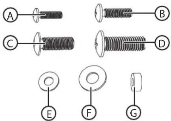
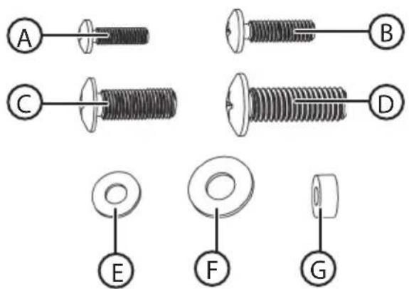
Pack M (fasteners)
A. M4×14 (×4)
B. M5x14 (x4)
C. M6×14 (×4)
D. M8x20 (x4)
E. M5 washer (x4)
F. M8 washer (x4)
G. Small spacer (x8)
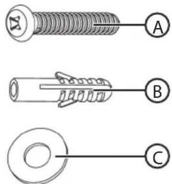
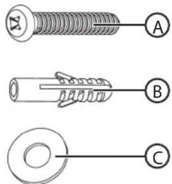
Pack W (fasteners for wall mounting)
A. ST 5.5×50 (x3)
B. Masonry wall plug (x3)
C. M6 washer (x3)
Assembly
Warning! Make sure that the wall you intend to attach the wall bracket to can bear the combined weight of the bracket and TV. If you are unsure, contact a tradesman. Make sure that you test the capacity of the bracket with a load of equal weight as the TV before mounting the TV onto it.
Screwing the articulated arm wall bracket to the wall
Important: The holes must be at least as deep as the length of the screws. If drilling into brick, drill at least 25 mm away from the edge of the brick. Do not drill into the mortar.
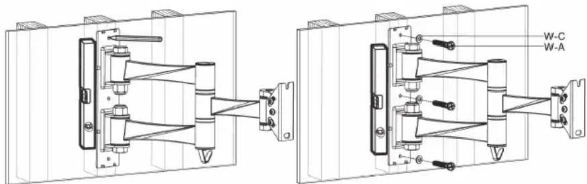
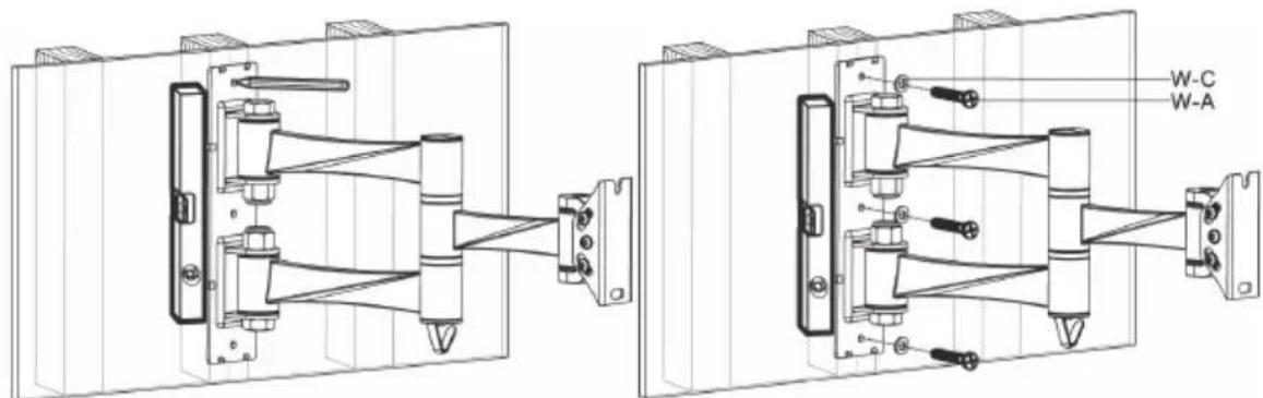
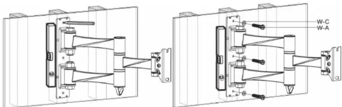
Wooden wall
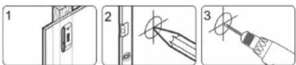
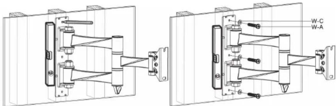
- 1-3. Measure, mark out and drill pilot holes. It is a good idea to use a stud detector on stud walls to help drill into the centre of the stud.
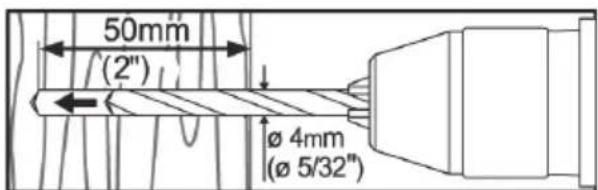
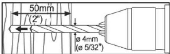
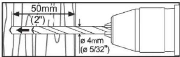
- 4. Drill the mounting holes 50 mm deep using a ∅ 4 mm (5/32") drill bit.
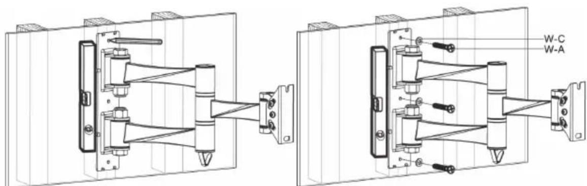
- 5. Screw the articulated arm wall bracket to the wall.
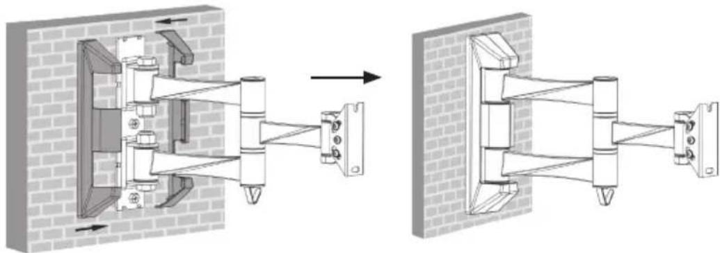
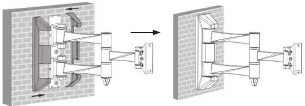
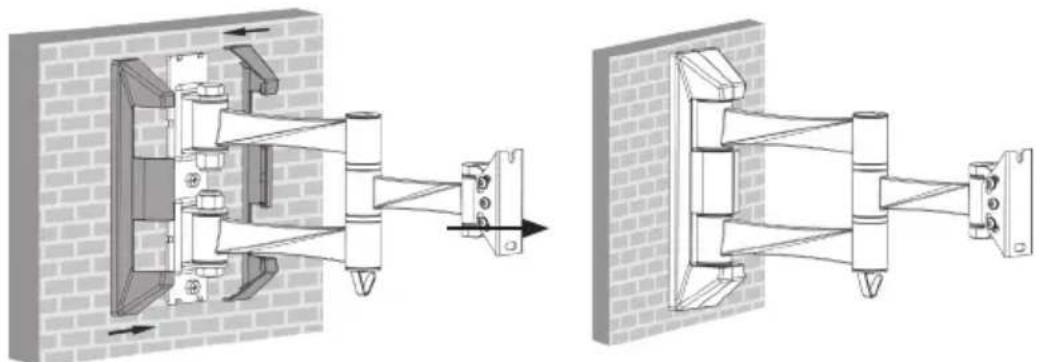
- 6. Push the right and the left decorative covers onto the articulated arm assembly.
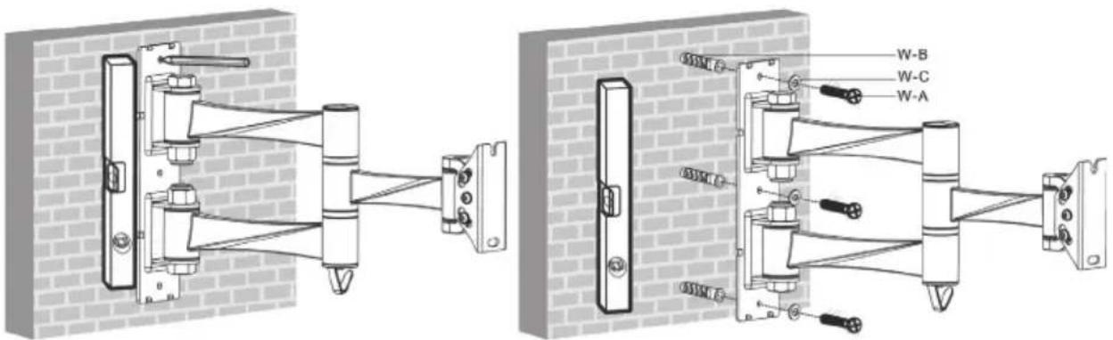
Masonry wall
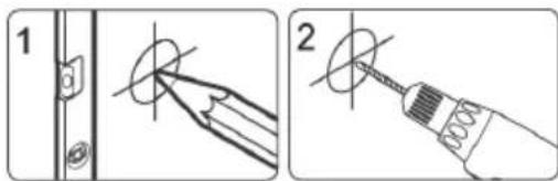
- 1-2. Measure, mark out and drill pilot holes. Use a hammer drill.
-
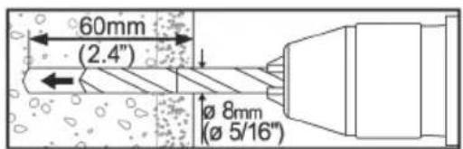
- Drill the mounting holes 60 mm deep using a ∅ 8 mm (5/16") drill bit.
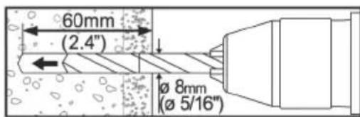
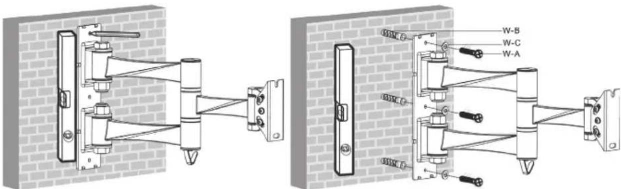
- 4. Screw the articulated arm wall bracket to the wall.
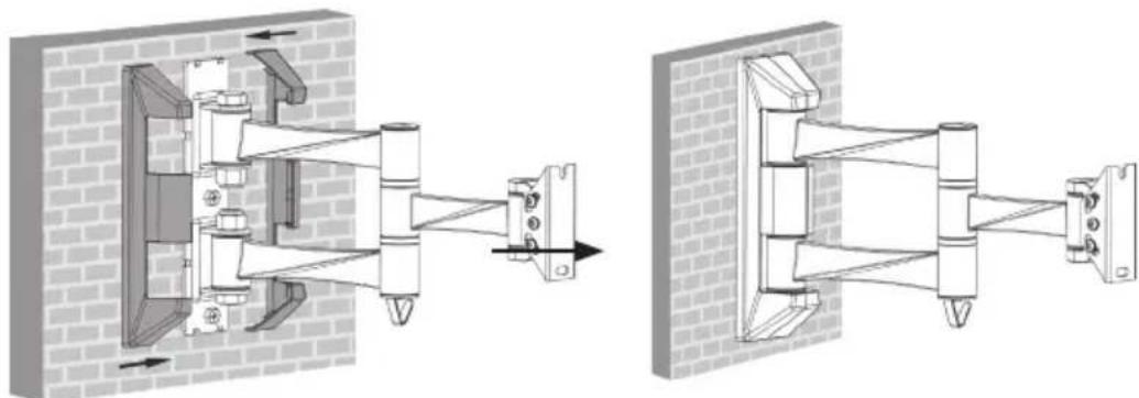
- 5. Push the right and the left decorative covers onto the articulated arm assembly.
Attaching the VESA plate to the TV/monitor

Detach the VESA plate from the articulated arm assembly. Leave the nut on the upper bolt, but remove the nut from the lower bolt.
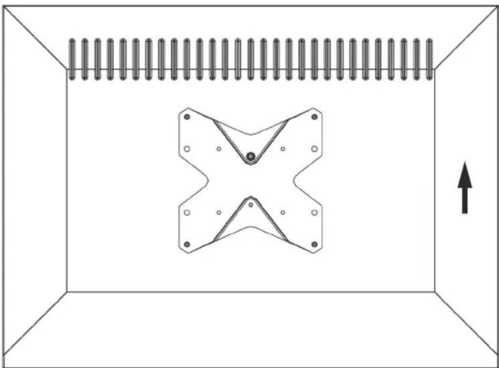
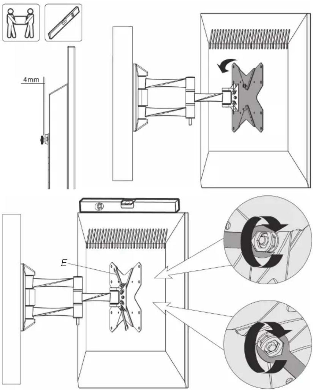
Align the VESA plate with the mounting holes in the back of the TV/monitor and attach the mount using suitable fasteners from Pack M. Tighten the fasteners using the spanner.
Attaching the TV/monitor to the articulated arm wall bracket
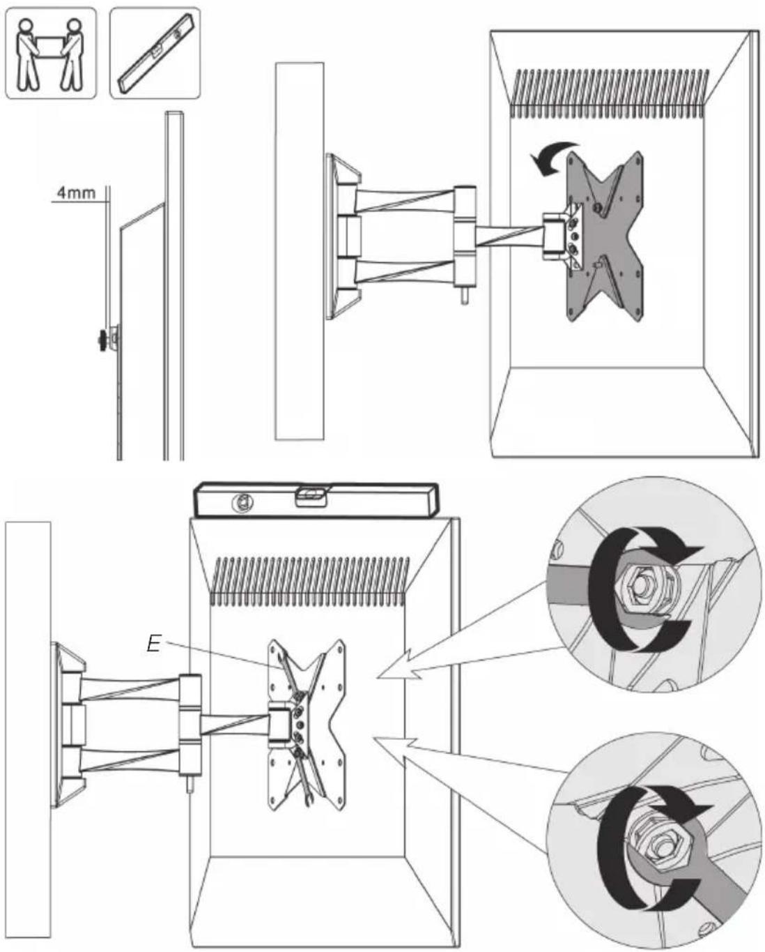
- Undo the upper nut on the VESA plate by 4 mm.
- Hang the TV/monitor and the VESA plate onto the articulated arm assembly.
- Use a spirit level to make sure that the TV/monitor is level.
- Screw on the lower nut and then tighten both the upper and lower nuts.
Hanging the cables
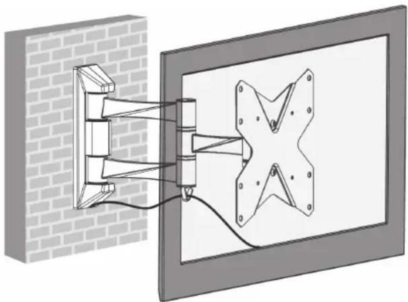
Hang the cables over the hook on the articulated arm wall bracket. Leave a little slack on the cable to allow for adjustment of the TV angle.
Adjusting the swivel and tilt angles
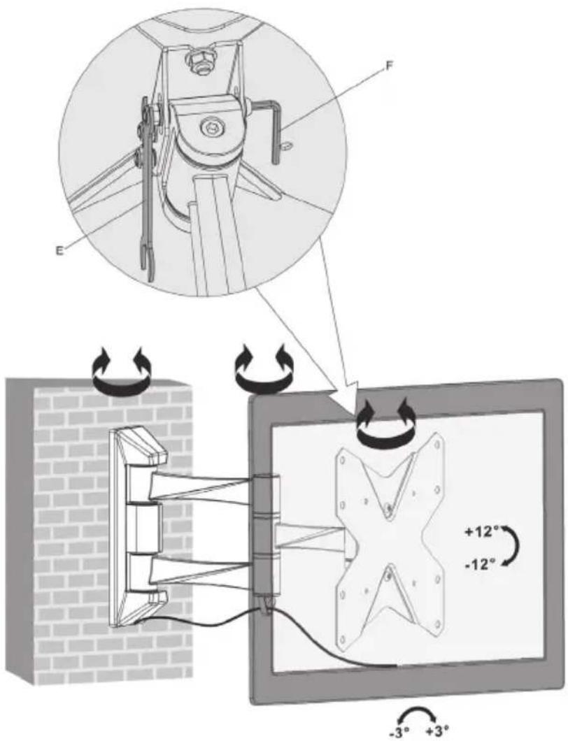
Loosen the bolts a little, adjust the angle and then retighten. Regularly check that the articulated arm wall bracket is securely mounted (at least every 3 months).
Disposal
This product should be disposed of in accordance with local regulations. If you are unsure how to proceed, contact your local authority.
Specifications
Tilt ± 12°
Mount VESA 100x100, 200x100 and 200x200 mm
Wall distance 340/220/60 mm
Load capacity 20 kg
Montering


Avfallshantering
Forpakning M (festedetaljer)
A. M4×14 (×4)
B. M5x14 (x4)
C. M6×14 (×4)
D. M8x20 (x4)
E. M5-skive (x4)
F. M8-skive (x4)
G. Distansestykke, kort (x8)
Forpakning W (festedetaljer for veggmontering)
A. ST 5,5x50 (x3)
B. Betongplugg (x3)
C. M6-skive (x3)
Montering

- 5. Skru opp veggfestet.

- 4. Skru opp veggfestet.
Plasser VESA-festet slik at det passer til festehullene på apparatet/monitoren. Velg riktige festeskruer og eventuelt distansestykker. Dra til alle skruene med nøkkelen.
Monter tv-apparatet/monitoren på veggfestet
Avfallshåndtering
Når produktet skal kasseres, må det skje i henhold til lokale forskrifter.
Asennus

Kierrättäminen
Montage
10 – 13 Market Place
Kingston Upon Thames
Surrey
KT1 1JZ
DEUTSCH


- ARTICULATED ARM TV/MONITOR BRACKET
- SAFETY
- NOTE
- IMPORTANT
- CONTENTS
- PACK M (FASTENERS)
- PACK W (FASTENERS FOR WALL MOUNTING)
- ASSEMBLY
- SCREWING THE ARTICULATED ARM WALL BRACKET TO THE WALL
- WOODEN WALL
- MASONRY WALL
- ATTACHING THE VESA PLATE TO THE TV/MONITOR
- ATTACHING THE TV/MONITOR TO THE ARTICULATED ARM WALL BRACKET
- HANGING THE CABLES
- ADJUSTING THE SWIVEL AND TILT ANGLES
- DISPOSAL
- SPECIFICATIONS
- MONTERING
- AVFALLSHANTERING
- FORPAKNING M (FESTEDETALJER)
- FORPAKNING W (FESTEDETALJER FOR VEGGMONTERING)
- MONTER TV-APPARATET/MONITOREN PÅ VEGGFESTET
- AVFALLSHÅNDTERING
- ASENNUS
- KIERRÄTTÄMINEN
- MONTAGE
- DEUTSCH
Brand : Exibel
Model : 38-5545
Category : Wall mount