380-075 - Log splitter Meec Tools - Free user manual and instructions
Find the device manual for free 380-075 Meec Tools in PDF.


| Product Type | Log Splitter |
| Brand | Meec Tools |
| Model | 380-075 |
| Splitting Force | 7 tons |
| Power Source | Electric, 230 V / 50 Hz |
| Motor Power | 1500 W (2 HP) |
| Max Log Length | 520 mm |
| Max Log Diameter | 250 mm |
| Cycle Time (Advance) | 4.5 seconds |
| Cycle Time (Retract) | 3.0 seconds |
| Hydraulic Oil Capacity | 2.5 liters |
| Dimensions (L x W x H) | 800 x 350 x 400 mm |
| Weight | 25 kg |
| Operation | Two-hand safety control |
| Safety Features | Emergency stop, overload protection |
| Wheels | 2 wheels for portability |
| Maintenance | Check oil level, clean air filter, lubricate moving parts |
| Recommended Oil | ISO VG 32 hydraulic oil |
| Noise Level | 85 dB (A) |
| Warranty | 2 years (subject to terms) |
Frequently Asked Questions - 380-075 Meec Tools
User questions about 380-075 Meec Tools
0 question about this device. Answer the ones you know or ask your own.
Ask a new question about this device
Download the instructions for your Log splitter in PDF format for free! Find your manual 380-075 - Meec Tools and take your electronic device back in hand. On this page are published all the documents necessary for the use of your device. 380-075 by Meec Tools.
USER MANUAL 380-075 Meec Tools
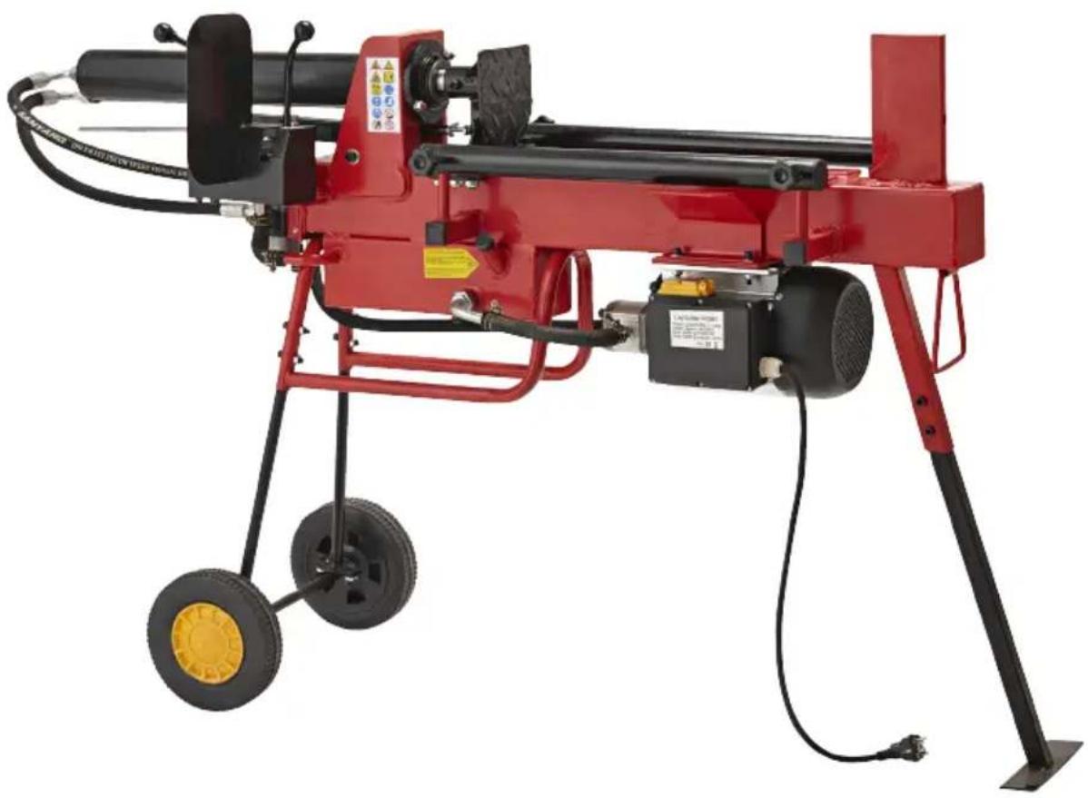
natural_image
Red industrial machine with wheels and control panel, no visible text or symbolsEN - Operating instructions (Translation of the original instructions)
Date of production: 2015-05-08
© Jula AB
SVENSKA....4
SÄKERHETSANVISNINGAR....4
Symboler 6
TEKNISKA DATA....7
BESKRIVNING 8
MONTERING 9
HANDHAVANDE 13
Före användning 13
Klyvning 14
UNDERHÅLL 15
FELSÖKNING....17
NORSK 19
SIKKERHETSANVISNINGER 19
Symboler 21
TEKNISKE DATA 22
BESKRIVELSE....23
MONTERING....24
BRUK....28
Før bruk 28
Kløyving 29
VEDLIKEHOLD 30
FEILS∅KING....32
POLSKI 34
ZASADY BEZPIECZEŃSTWA 34
Symbole 36
DANE TECHNICZNE 37
OPIS 38
MONTAŻ 39
OBSŁUGA 43
Przed użyciem....43
Rozłupywanie 44
KONSERWACJA 45
WYKRYWANIE USTEREK 47
ENGLISH 49
SAFETY INSTRUCTIONS 49
Symbols 51
TECHNICAL DATA....52
DESCRIPTION 53
ASSEMBLY 54
USE....58
Before use. 58
Cleaving 59
MAINTENANCE 60
TROUBLESHOOTING 62
SÄKERHETSANVISNINGAR
natural_image
Close-up of a robotic arm with articulated legs and a camera, no visible text or symbols
natural_image
Mechanical assembly diagram showing a bracket with mounting flanges and directional arrows indicating force or movement (no text or symbols present)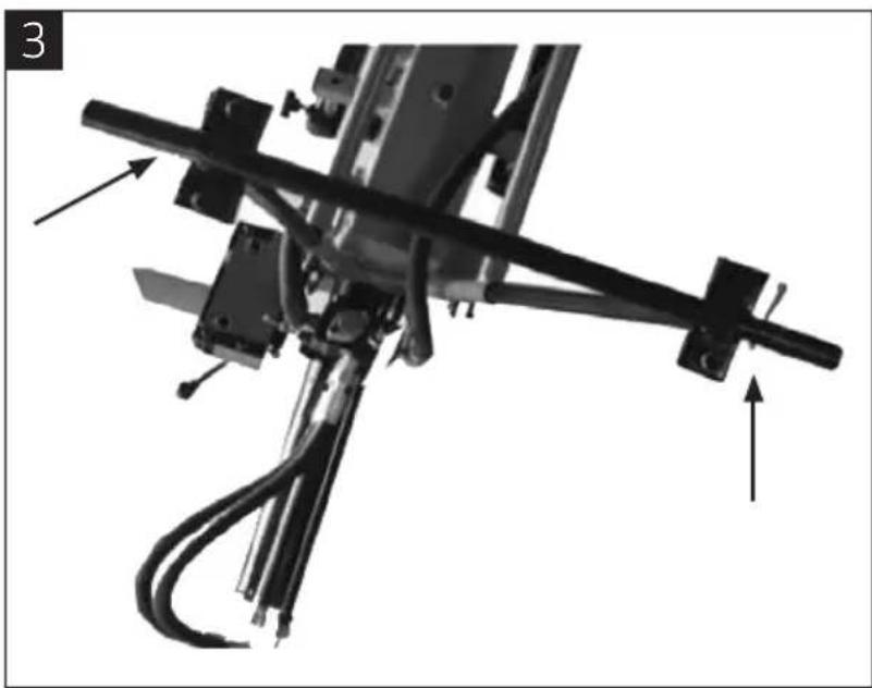
natural_image
Mechanical assembly diagram showing a linkage mechanism with arrows indicating motion direction (no text or symbols present)4
natural_image
Mechanical assembly diagram showing a hand adjusting a tire, alongside a vehicle with wheels and a mounted device (no text or symbols visible)5
natural_image
Three-panel black-and-white photo showing hands operating a mechanical leg, with no visible text or symbols.natural_image
Mechanical assembly diagram showing a rotating component with mounting flanges and a directional arrow (no text or symbols)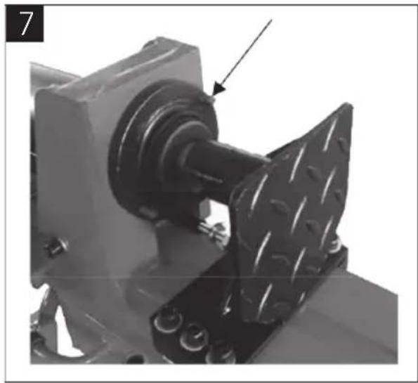
natural_image
Mechanical assembly with a metallic component and a textured plate, no visible text or symbols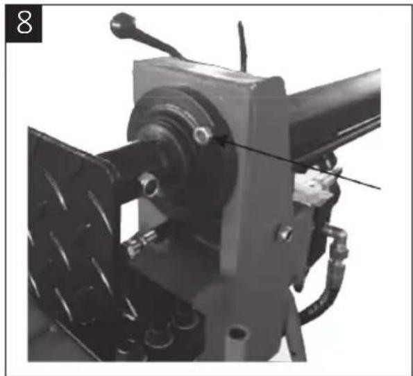
natural_image
Mechanical assembly with a mounted component and pipe fittings (no visible text or symbols)natural_image
Mechanical assembly with mechanical components and directional arrows indicating motion (no text or symbols)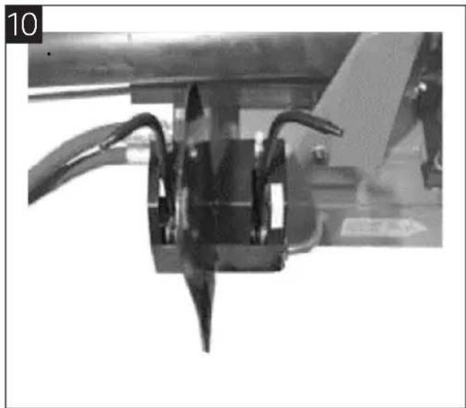
natural_image
Close-up of a mechanical assembly with curved wires and a pointed tip (no visible text or symbols)HANDHAVANDE
FÖRE ANVÄNDNING
natural_image
Close-up of a mechanical component with a circular inset showing a pin and lever (no text or symbols visible)KLYVNING
OBS!
natural_image
Technical line drawing of a mechanical device with wheels and a cross mark (no text or symbols)natural_image
Mechanical device with attached motors and wheels, no visible text or symbols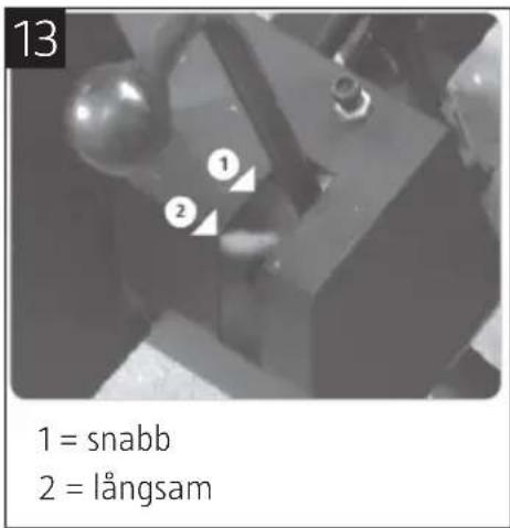
natural_image
Technical line drawing of a mechanical device with wheels and a downward arrow indicating motion (no text or symbols)natural_image
Simple line drawing of a trash bin with diagonal lines crossing it, no text or symbols present.Värna om miljön!
natural_image
Mechanical device with articulated legs and a camera, no visible text or symbols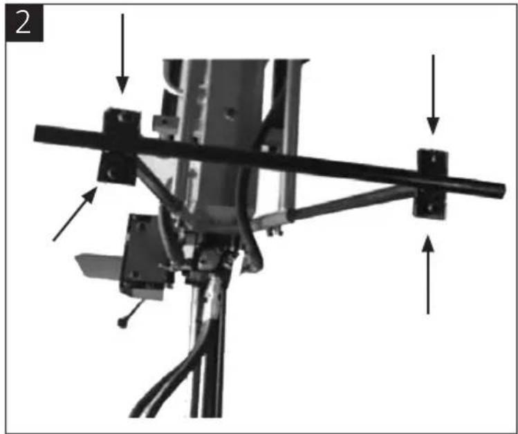
natural_image
Mechanical assembly diagram showing a bracket with mounting points and directional arrows (no text or symbols)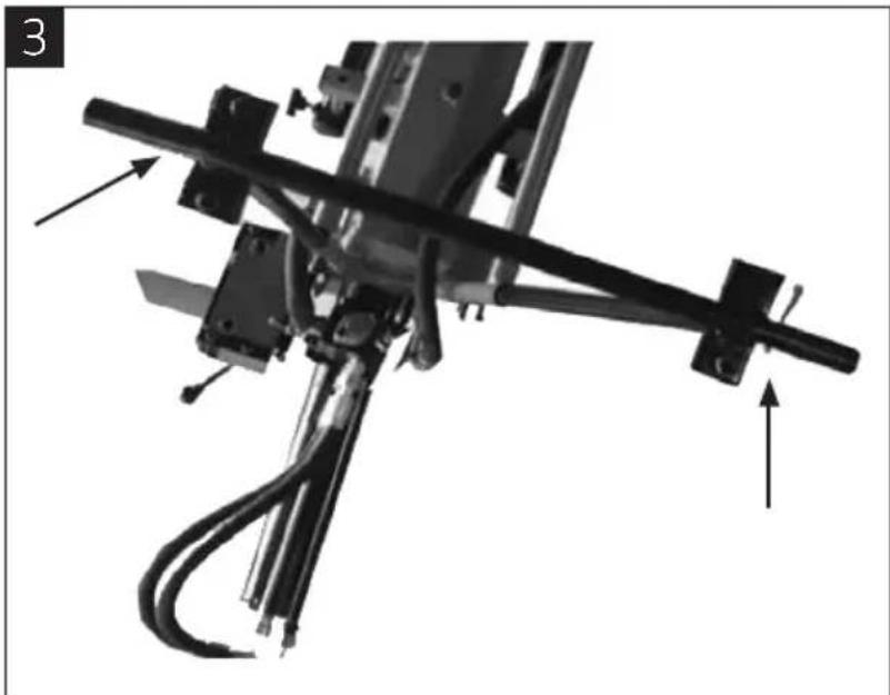
natural_image
Mechanical assembly diagram showing a linkage mechanism with arrows indicating motion direction (no text or symbols present)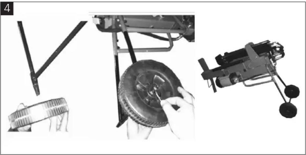
natural_image
Mechanical assembly diagram showing motor components and a tire assembly (no text or labels)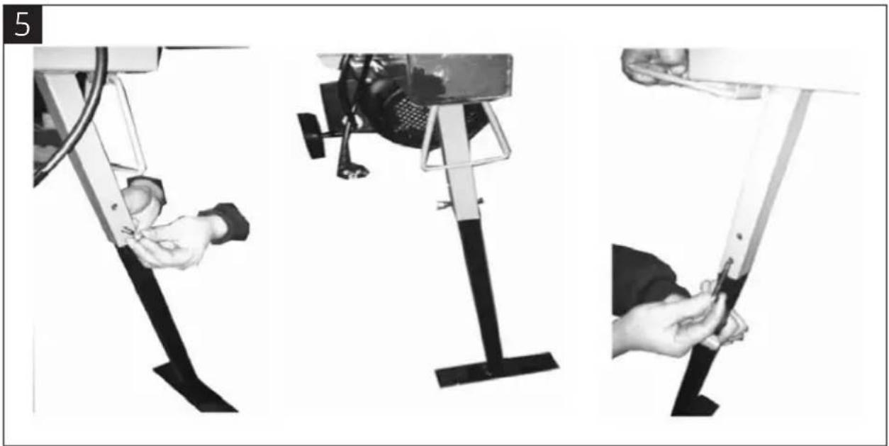
natural_image
Three-step diagram showing a person using a leg-mounted device to adjust the base of a vehicle (no text or symbols present)natural_image
Mechanical assembly with a metallic frame and mounting bracket, showing motion direction (no text or symbols)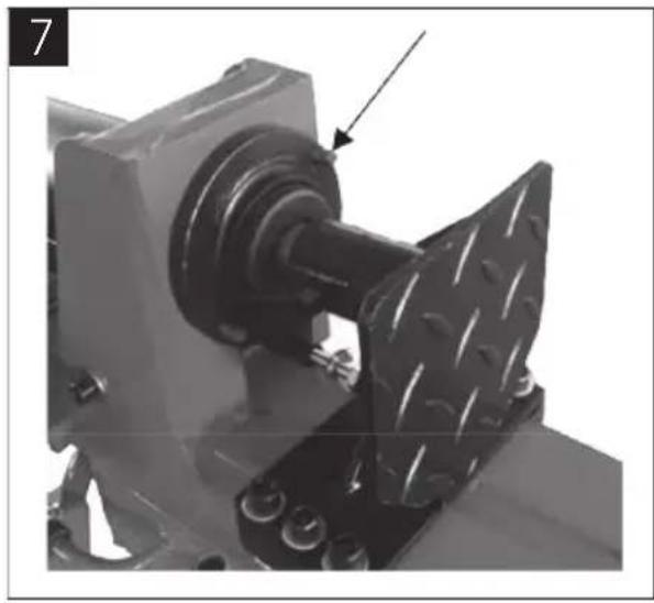
natural_image
Mechanical assembly with a metallic component and bolted base, no visible text or symbols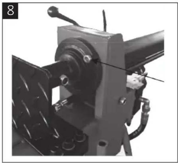
natural_image
Mechanical assembly with attached components and a tool, no visible text or symbolsnatural_image
Mechanical assembly diagram showing mechanical components with arrows pointing to specific parts (no text or symbols present)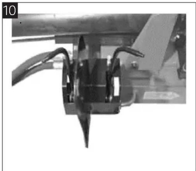
natural_image
Close-up of a mechanical assembly with wires and components (no visible text or symbols)BRUK
F∅R BRUK
natural_image
Close-up of a mechanical component with a circular inset showing a pin or bracket (no text or symbols visible)KL∅YVING
OBS!
natural_image
Technical line drawing of a mechanical device with wheels and a cross mark (no text or symbols)-
Koble vedkløyveren til strømforsyningen og start den.
-
Legg en kubbe på arbeidsbordet.
natural_image
Mechanical device with attached motors and wheels, no visible text or symbols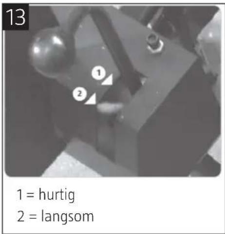
Løsne fastklemte kubber
natural_image
Technical line drawing of a mechanical device with wheels and a downward arrow indicating motion (no text or symbols)natural_image
Mechanical device with articulated legs and a camera, shown in black and white (no visible text or symbols)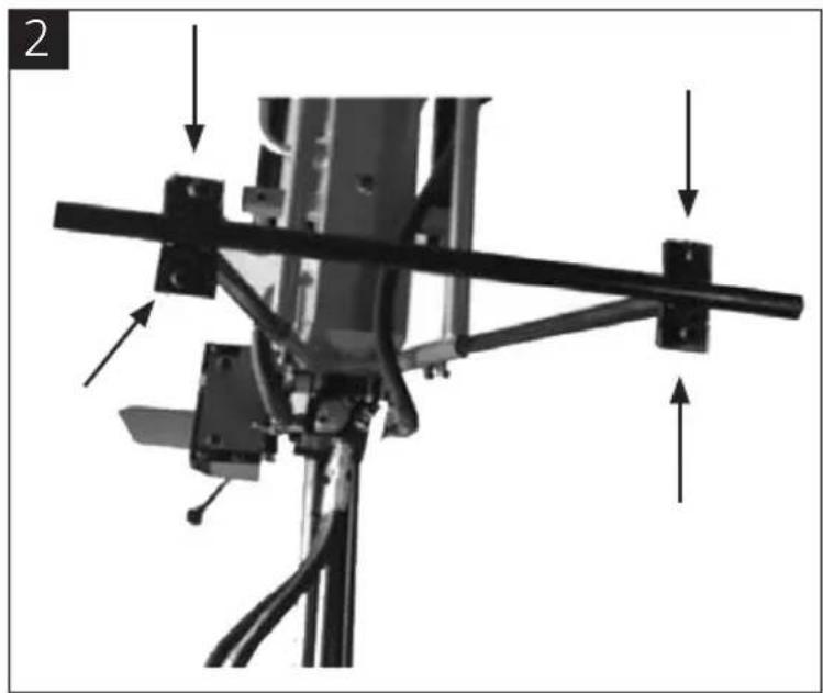
natural_image
Mechanical assembly diagram showing a bracket with mounting hardware and directional arrows indicating force or movement (no text or symbols present)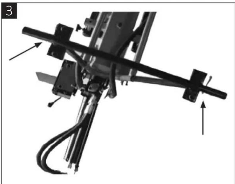
natural_image
Mechanical assembly diagram showing a linkage mechanism with labeled components and directional arrows (no text or symbols present)4
natural_image
Black-and-white photo showing mechanical components including a tire, wheel assembly, and a small vehicle (no visible text or symbols)5
natural_image
Three-panel black-and-white photo showing hands operating a mechanical leg, with no visible text or symbols.Montaż cylindra
natural_image
Mechanical assembly diagram showing a motor drive with rotating components and an arrow indicating motion (no text or symbols)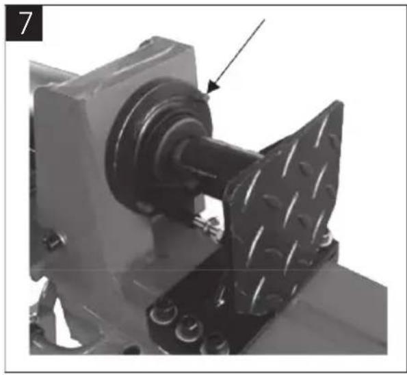
natural_image
Mechanical assembly with a metallic component and bolted base, no visible text or symbols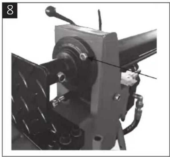
natural_image
Mechanical assembly with attached components and a tool, no visible text or symbolsnatural_image
Close-up mechanical assembly with arrows pointing to specific components (no visible text or symbols)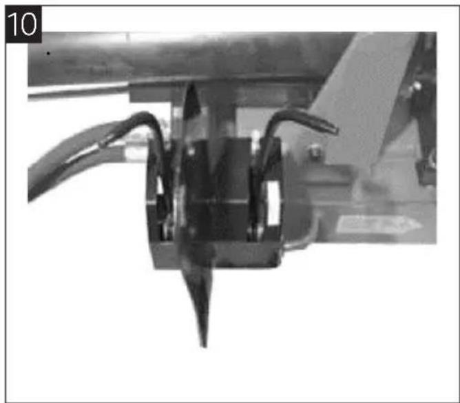
natural_image
Close-up of a mechanical component with curved wires and a pointed tip, no visible text or symbolsOBSŁUGA
PRZED UŻYCIEM
natural_image
Close-up of a mechanical component with a circular inset showing a pin and cable (no text or symbols visible)ROZŁUPYWANIE
UWAGA!
natural_image
Technical line drawing of a mechanical device with wheels and a cross mark (no text or symbols)natural_image
Mechanical device with attached motors and wheels, no visible text or symbols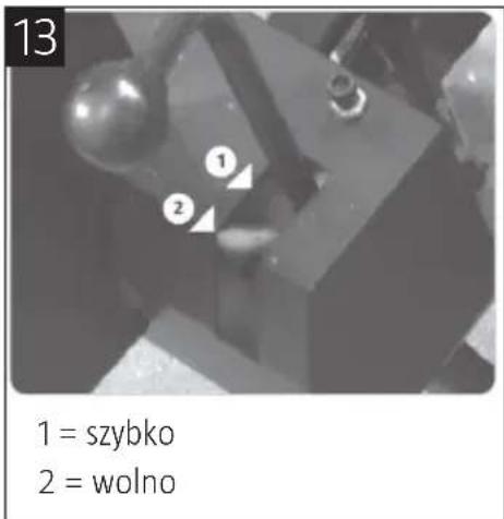
natural_image
Technical line drawing of a mechanical device with wheels and a downward arrow indicating motion (no text or symbols)natural_image
Pure electrical circuit lines without any symbolsDBAJ O ŚRODOWISKO!
Read the user instructions carefully before use!
Save these instructions for future reference.
- Read all warnings, safety instructions and other directives carefully before use. Do not use the tool for anything other than the purpose for which it is intended to be used for. Failure to follow all the instructions and safety instructions can result in a risk of personal injury and/or material damage. Save these instructions for future reference.
- The log splitter is not intended to be used by persons (children or adults) with any form of functional disorders, or by persons who do not have sufficient experience or knowledge on how to use it, unless they have received instructions concerning the use of the log splitter from someone who is responsible for their safety. Keep children under supervision to make sure they do not play with the log splitter. Do not allow children to use, clean or maintain the log splitter without supervision.
- Read all the instructions and warning labels on the log splitter prior to use, in order to understand its area of application, its limitations and possible risks.
- Never use the log splitter if you are tired or under the influence of drugs, alcohol or medication. Stay alert at all times. Use your common sense.
- Place the log splitter on a flat, stable, horizontal bench or the like, with plenty of space for the user to handle the logs. Screw the log splitter to the base surface if it slides. Keep the work area clean and well lit. Dark and cluttered work areas increase the risk of accidents and injuries. Do not use the log splitter in damp or wet areas. Do not expose the log splitter to rain. The surface must not be slippery. Select a flat, dry surface without high grass or other obstacles. Keep the work area free of tools, pieces of wood and the like. Clean regularly removing shavings and pieces of wood from the work area. Do not use the log splitter in explosive environments, such as in the vicinity of flammable liquids, gases or dust.
- Always inspect the log splitter before use. Safety devices must be fitted correctly and function properly. Always check that hex keys/spanners etc. have been removed from the log splitter before starting it. Replace any damaged, missing or broken parts prior to use.
- Do not wear loose-fitting clothes, jewellery, or watches etc. that can fasten in moving parts. They can get caught in moving parts. Safety gloves that are not electrically conductive as well as non-slip shoes are recommended. Wear a hair net if you have long hair.
- The log splitter can eject objects that can cause permanent eye injuries. Wear safety glasses. Normal glasses only have shock-resistant lenses. They are not safety glasses. Do not use the log splitter placed on the floor or ground. This results in a poor working position where the user's face comes close to the log splitter - danger of being hit by splinters and the like.
- Unsuitable extension cords can cause a fire and/or electric shock. Do not use extension cords longer than 10 m. Extension cords must have a conductor cross-section of at least 1.5 mm2 to withstand the motor's power supply. Do not use insufficiently insulated connections. Connections must be appropriate for outdoor use.
- Check that the mains voltage corresponds to the rated voltage on the type plate and that the circuit is correctly fuse protected. Check that the cable is earthed or grounded and fitted with an RCD. The log splitter must only be connected to a correctly earthed mains outlet. Avoid body contact with earthed surfaces such as pipes, radiators, cookers and refrigerators. Never open the pushbutton box on the motor. The box must only be opened by authorised electricians. Electrical connections and other electrical work must only be carried out by an authorised electrician. Do not touch metal parts of the plug when connecting or disconnecting it.
- The log splitter must only be used by one person at once. Keep onlookers at a safe distance when using the log splitter. Never allow anyone to help you release logs that have become stuck.
- Check that there are no nails or other foreign objects in the logs. The ends of the logs must be cut perpendicularly. Branches should be cut next to the log. Never attempt to cut logs across the grain. Never try to split two or more logs simultaneously. Never try to split a log that is not properly positioned on the work table.
- Always maintain a firm footing and good balance. Never stand on the log splitter. You could be seriously injured if the log splitter tips over or if you come into contact with sharp parts. Do not store anything above or close to the log splitter, where someone may be tempted to stand on the log splitter in order to reach.
- Watch out for the log splitter's movements. Do not attempt to add or remove logs until the log pusher has completely stopped in its starting position. Keep your hands away from all moving parts.
- Keep your hands at a safe distance from cracks that open up in the wood. Such cracks may close suddenly and crush or amputate your hands. Do not use your hands to release a log that has become stuck.
- The log splitter will work better and more safely at the load for which it is intended. Do not try to split logs larger than that permitted according to the
technical data. This can involve a risk of serious personal injury and/or material damage. Do not use the log splitter for anything other than the purpose for which it is intended to be used for.
- Do not leave the log splitter until it has come to a complete standstill.
- Switch off the motor when the log splitter is not used and before carrying out any adjustments, replacing parts, cleaning or doing maintenance work. Read these instructions before servicing.
• Used oil must be disposed of in accordance with local regulations. - Keep the log splitter clean and in good condition for better and safer work.
- Keep the workshop locked. Turn off the main switch. Store the log splitter out of the reach of children and unauthorised persons. Never allow children, or anyone who is unfamiliar with the log splitter and these instructions, to use it. The log splitter is dangerous if used by inexperienced people.
SYMBOLS
 | Read the user instructions carefully before use. |
 | Wear safety gloves |
 | Wear ear protection and safety glasses. |
 | Wear safety shoes |
 | IMPORTANT: Risk of pinch injury. |
 | WARNING: Moving parts. Do not allow any part of your body to come between the wood and the piston when the machine is working. |
 | Never attempt to remove wood that has got stuck, or clear the blade with your bare hands. |
 | Avoid using the log splitter when other persons, especially children, are nearby. |
 | Remove the plug from the power outlet when the work is finished and before starting repairs or maintenance work. |
 | Protect the environment. Always recycle used oil. Do not pour oil into drains, soil or water. |
 | Do not touch moving parts. |
 | Inspect the log splitter. Check the log splitter before use. Make sure all parts are complete and in working order, and that there are no tools or other items on the work bench. Replace damaged or missing parts before use. |
TECHNICAL DATA
Rated voltage 230 VAC, 50 Hz
Output: 2100 W
Speed 2800 rpm
Protection rating IP54
Splitting force 9 tonnes
Log length 520 mm
Log diameter 70–300 mm*
Hydraulic oil volume 3.5 l
Hydraulic pressure 21 MPa
Height 570 mm
Width 395 mm
Length 1460 mm
Weight 80 kg
Noise level ≤ 70 dB(A)
Vibration, control handle 2.5 m/s ^4
Always wear ear protection!
The product complies with the requirements according to quality class HA ISO 2807.
* The specified diameter are only indicative. A thinner log may be more difficult to split if it has knots
or especially tough fibres. On the other hand, logs with a larger diameter may be easier to split if the fibre structure is even
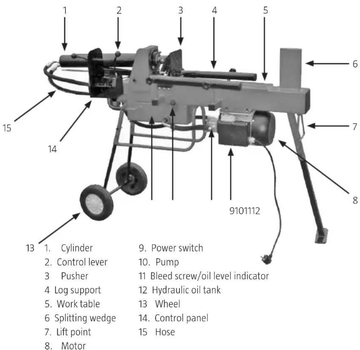
DESCRIPTION
NOTE:
- The log splitter is designed for household use only.
• Stocks should be split along the grain. Never attempt to cut logs across the grain. - Do not use the log splitter at temperatures below 5^ .
- The log splitter can be stored and transported at ambient temperatures between -40 and 30 °C.
ASSEMBLY
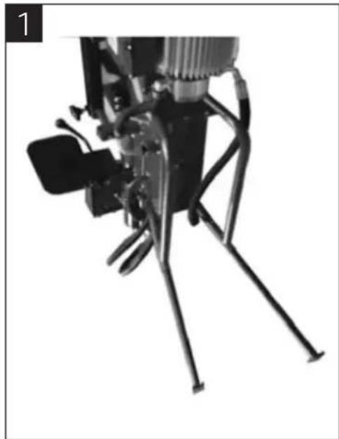
Assembling the legs
- Insert the rear legs in the round tubes and lock in position with two screws on each leg (Figure 1).
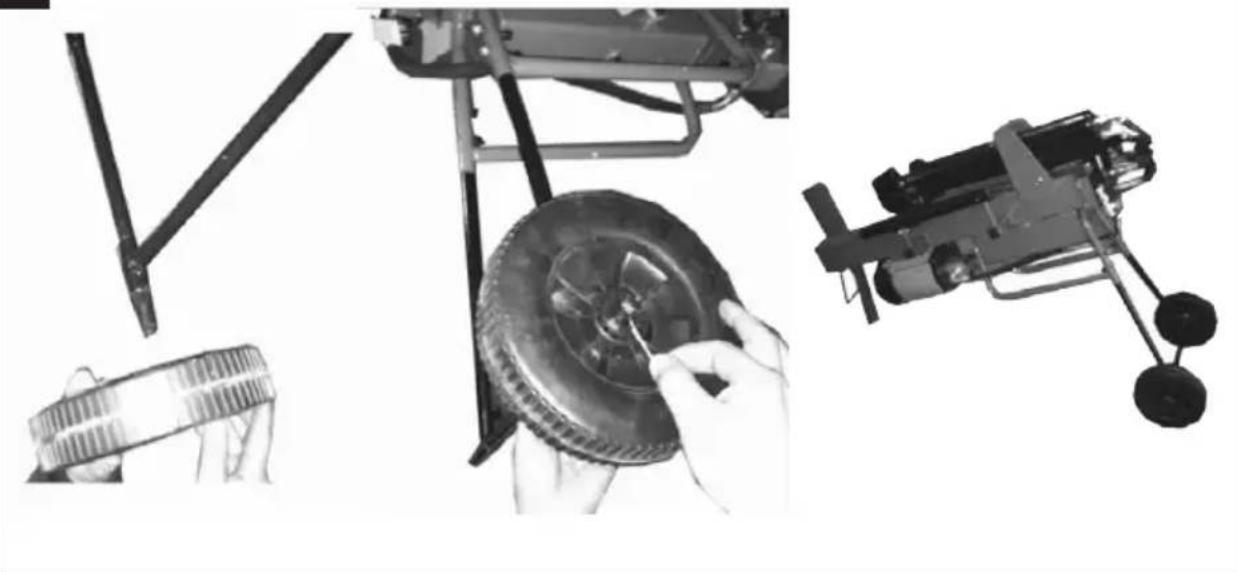
- Fit the wheel axle with four screws (Figure 2).
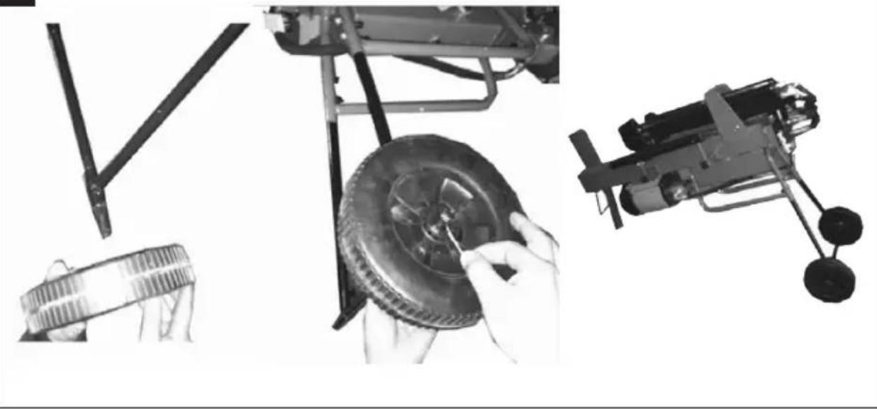
- Insert a cotter pin into the axle (Figure 3), push on the wheel and insert a cotter pin on the other side of the wheel (Figure 4).
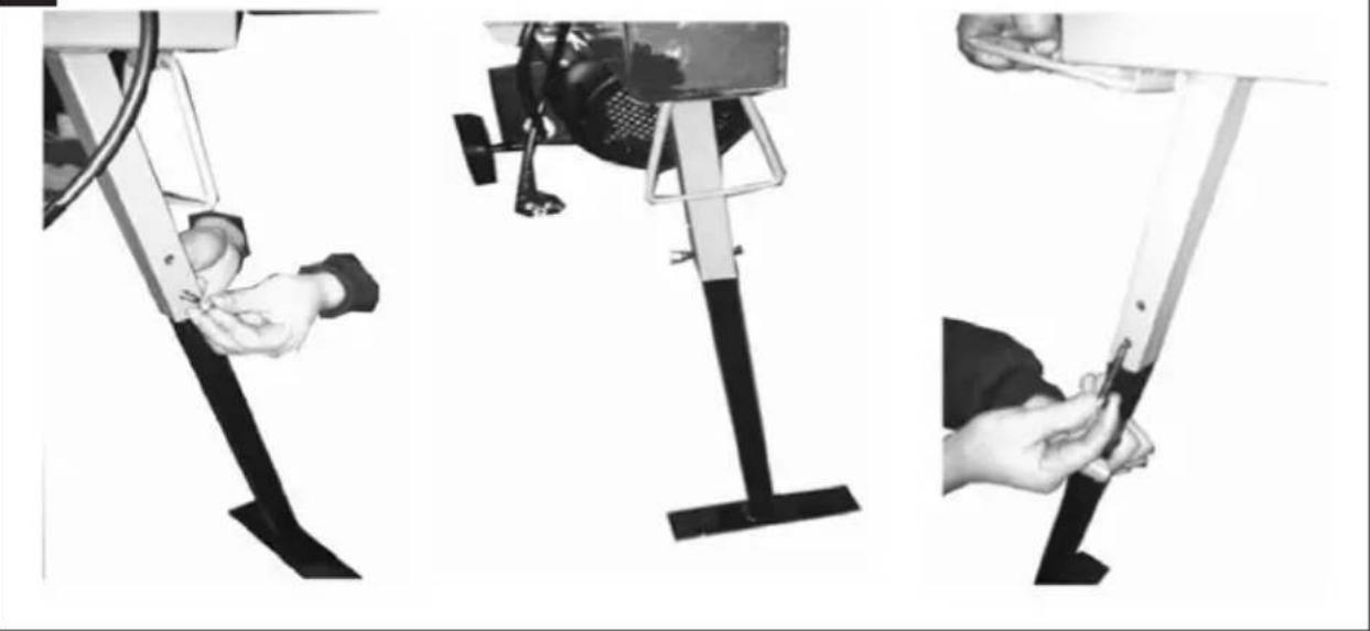
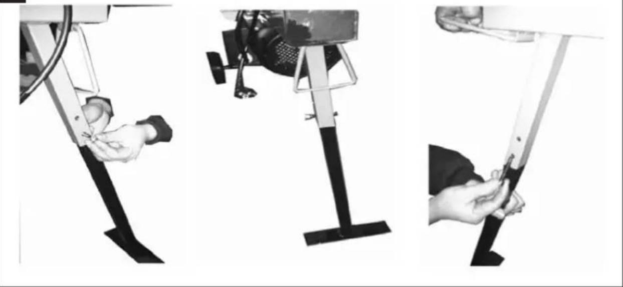
- Lift up the end of the splitting wedge and fit the front legs with screws and nuts (Figure 5).
natural_image
Mechanical device with articulated legs and a camera, no visible text or symbols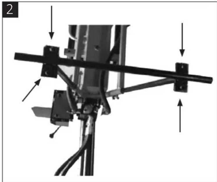
natural_image
Mechanical assembly diagram showing a bracket with mounting points and directional arrows (no text or symbols)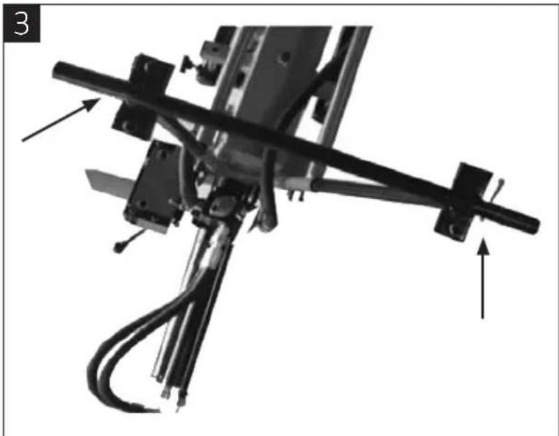
natural_image
Mechanical assembly diagram showing a linkage mechanism with arrows indicating motion direction (no text or symbols present)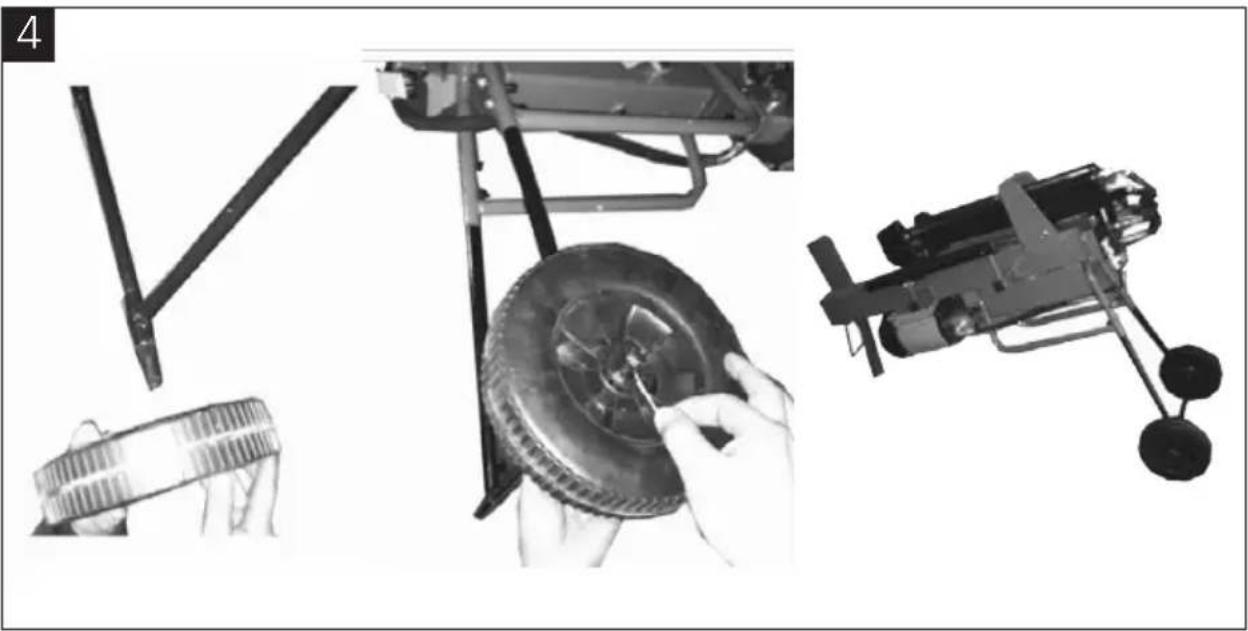
natural_image
Mechanical assembly diagram showing components like a tire, wheel, and motor (no text or symbols)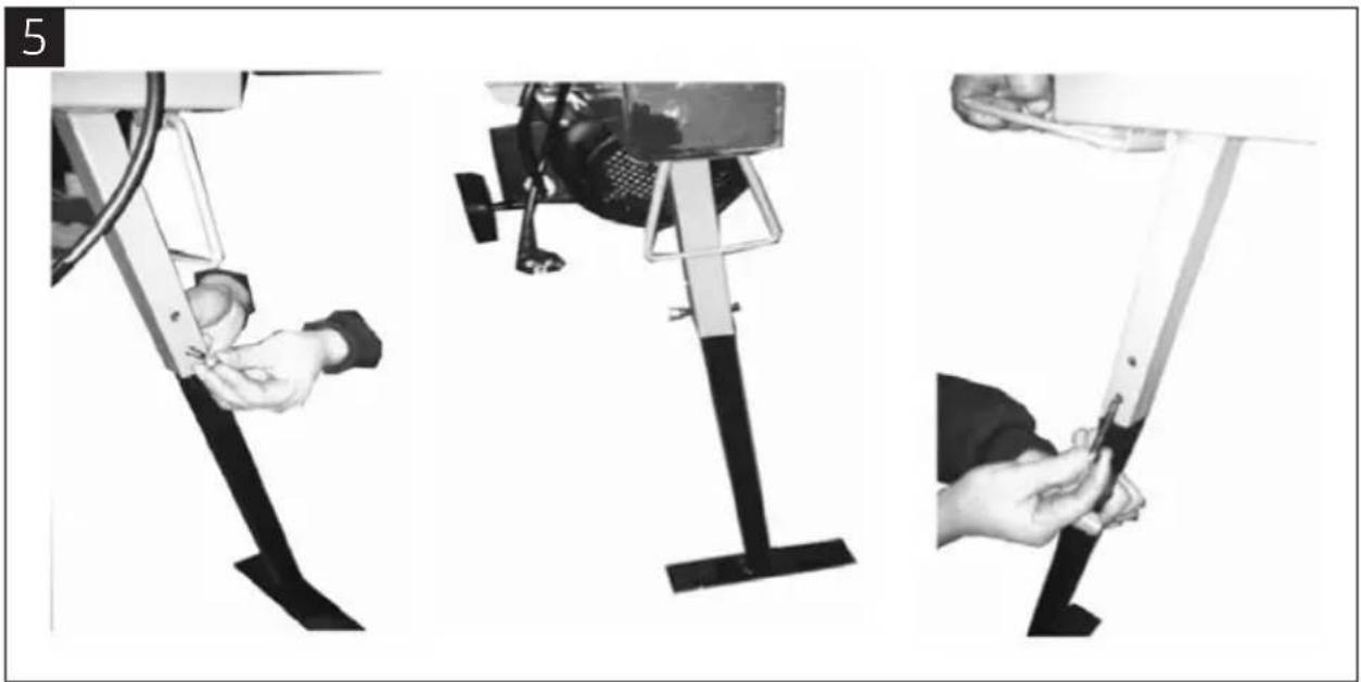
natural_image
Three-step diagram showing a person using a leg-mounted device to adjust the base of a vehicle (no text or symbols present)Assembling the cylinder
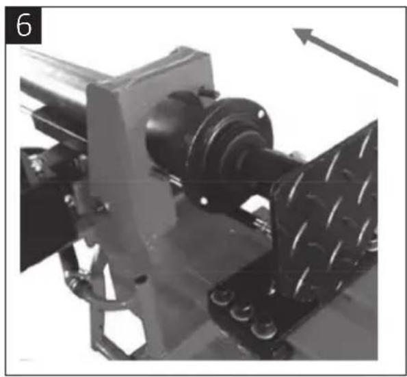
- Push the cylinder away from the splitting wedge (Fig 6).
- Lift the cylinder slightly and move it sideways to fit the screws into the holes in the cylinder (Figure 7).
- Lock in place with two nuts (Figure 8).
natural_image
Mechanical assembly diagram showing a rotating component with mounting flanges and a directional arrow (no text or symbols)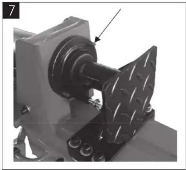
natural_image
Mechanical assembly showing a rotating component with a textured metal plate and an arrow pointing to a feature (no text or symbols visible)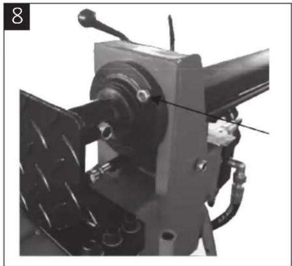
natural_image
Mechanical assembly with attached components and a tool, no visible text or symbolsAssembling the control unit
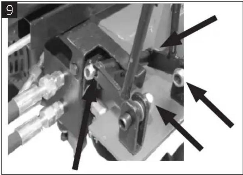
- Remove the nuts and fit the control levers as shown in (Figure 9). Tighten all the bolted joints.
- Unscrew and remove the lever knobs. Position the control cover. Screw on the housing from below using three hexagonal screws. Screw on the knobs again (Figure 10).
natural_image
Mechanical assembly with arrows pointing to specific components (no visible text or symbols)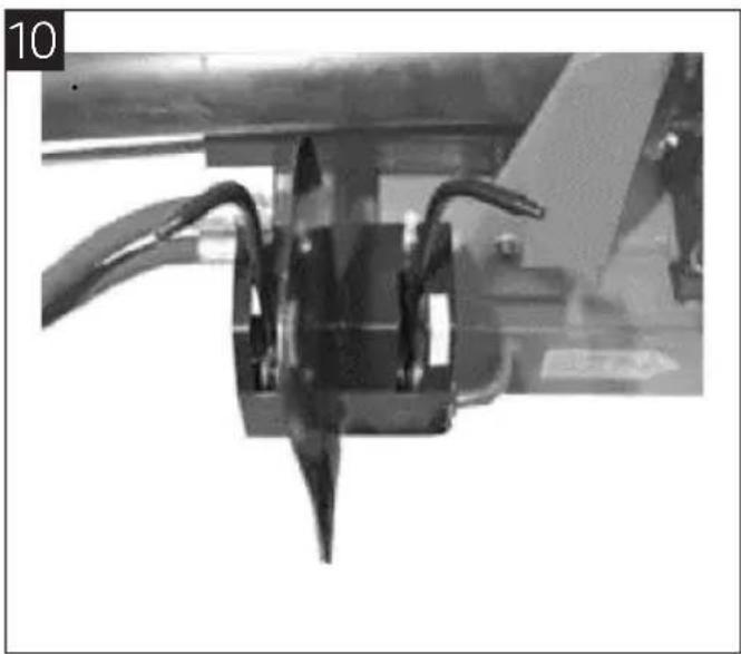
natural_image
Close-up of a mechanical component with two curved wires and a central spike (no visible text or symbols)USE
BEFORE USE
- Always check that the log splitter is in good condition before use. Check all the hydraulic hoses and connections for leakage.
- Do not use the log splitter unless all the safety devices and guards are correctly installed and working
- Plan the work. Good planning makes work easier and safer. Place the logs so that they are easy to reach. Plan the work so that you can easily place the split logs directly in the right place (for example on a platform). Prepare the logs for splitting. The log splitter can handle logs with length of up to 52 cm and a diameter of 30 cm.
Open the bleed screw
NOTE:
- If the bleed screw is not opened the air remaining in the hydraulic system becomes compressed. This destroys the seals and will damage the log splitter permanently.
-
Check that the bleed screw is tightened securely before moving log splitter in order to avoid oil leakage.
-
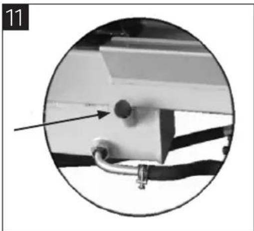
Before using the log splitter, open the bleed screw (Figure 11) a few turns to allow air to pass in and out of the oil tank.
- The air flow through the vent hole should be noticeable when the log splitter is used.
natural_image
Close-up of a mechanical component with a circular inset showing a pin and cable (no text or symbols visible)CLEAVING
NOTE:
- Switch off the motor immediately if the log splitter does not work normally. Check and rectify the reason before using the log splitter again.
- Stocks should be split along the grain. Never attempt to cleave a log across the grain with the log splitter, it may cause personal injury and/or serious damage to property.
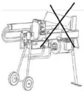
- Never try to split two or more logs simultaneously. One can be thrown out and cause personal injury and/or material damage.
natural_image
Technical line drawing of a mechanical device with wheels and a cross mark (no text or symbols)-
Connect the log splitter to the mains supply and start the log splitter.
-
Place a log on the work table.
- Place the log so that it can rotate, tilt or slide during cleaving. Do not place the log on the top part of the cleaver knife, it can damage the cleaver knife and/or the log splitter.
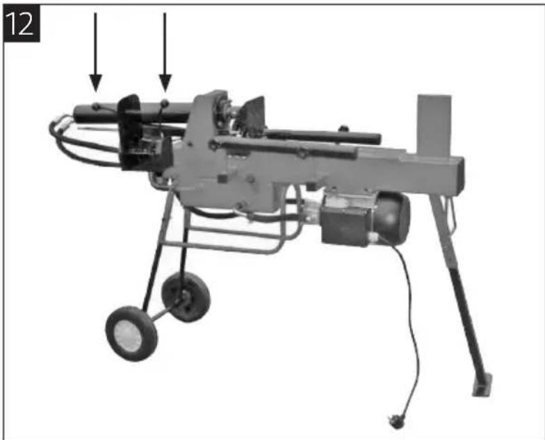
- The log splitter's control system must be operated with one hand on each lever (Figure 12).
- If you release any of the levers the log splitter will stop moving. Only when you released both levers will the pusher begin to move back to the starting position.
- Never hold the levers pressed for longer than 5 seconds to try to cleave hard logs. If you hold the levers pressed longer, the hydraulic oil will overheat and damage the log splitter.
- If it is not possible to cleave the log, turn it 90^ and try again. If you are still unable to cleave the log it should be rejected.
- The log splitter has a two-way valve for speed control (Figure 13).
- Push the levers down a little, fast forward motion.
- Press down the levers fully, for a lower speed during cleaving.
natural_image
Mechanical device with attached motors and wheels, no visible text or symbols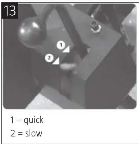
Releasing jammed logs
NOTE: Never try to hit or knock loose a jammed log. This may damage the log splitter or cause the log to suddenly release and cause injury.
- Release both control levers. When pusher has returned and stopped at the starting position, place a wooden wedge under the jammed log.
- Run the log splitter so that the wooden wedge is pressed in under the jammed log. Repeat with thicker wedges until the log releases.
MAINTENANCE
Changing the hydraulic oil
The hydraulic oil in the log splitter should be changed after an interval of 150 working hours. Check at regular intervals that the oil level is between the two markings on the dipstick. Top up the hydraulic oil if the level is too low.
- Switch off the engine and wait until all moving parts have completely stopped.
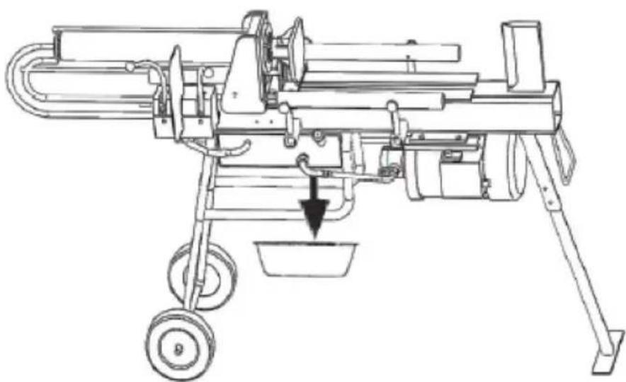
- Place a container that holds at least 3,5 litres under the oil drain plug. Unscrew and remove the plug. Allow the oil to run out.
- Clean the oil drain plug and replace. Fill up with new hydraulic oil. The hydraulic oil tank holds 3,5 l. Check that no oil is leaking out.
- Remove and clean the oil tank cap and dipstick, and then replace in the tank. Remove the dipstick again and check that the oil level is between the two markings.
The following hydraulic oils or equivalent can be used. ISO VG32 and ISO VG 46.
natural_image
Technical line drawing of a mechanical device with wheels and a downward arrow indicating motion (no text or symbols)Sharpening the splitting wedge
Over time, the splitting wedge become dull and needs to be sharpened. Remove all burrs and damage along the edge with a fine file.
Maximum pressure
- The permitted maximum pressure is set at the factory and the set screw is sealed to ensure that the log splitter's operating pressure never exceeds the permitted value.
- Never try to change the set maximum pressure. If the setting is changed, there is a risk of damage to property or that the hydraulic pump does not provide enough pressure.
Transport
- Check that the bleed screw is tightened.
- The log splitter is equipped with two wheels for small movements.
- Switch off the motor and wait until all moving parts have completely stopped before handling, moving and/or transporting.
TROUBLESHOOTING
| Problem Cause Action | ||
| The motor will not start. | Overload protection has tripped. | Let a qualified service technician reset the overload protection. |
| Cleaving is not possible. | The log is incorrectly positioned.The log is too big or too hard to be cleaved.The edge of the splitting wedge is blunt.Oil leak.The adjusting screw for the maximum pressure is set to a lower maximum pressure, despite this not being permitted. | Place the log as directed.Do not exceed the specified sizes and do not try to cleave very hard or fibrous wood.Sharpen the splitting wedge in accordance with these instructions.Locate the leak and contact a qualified service technician.Contact a qualified service technician. |
| The pusher moves erratically, the log splitter is noisy or vibrates. | Too little hydraulic oil and too much air in the hydraulic system. | Check the oil level, and top up the oil if necessary. |
| Oil leak. • Air in the hydraulic system. | The bleed screw is not tightened when moving the log splitter.The drain plug is not tightened sufficiently.Worn seals/valves. | Open the bleed screw few turns before use.Tighten the bleed screw before moving the log splitter.Tighten all the drain plug.Contact a qualified service technician. |
Jula reserves the right to make changes. In the event of problems, please contact our service department. www.jula.com
natural_image
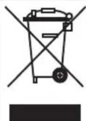
Simple line drawing of a trash bin with no text or symbolsCare for the environment!
Must not be discarded with household waste!
This product contains electrical or electronic components that should be recycled.
Leave the product for recycling at the designated station e.g. the clocal authority's recycling station.

EC DECLARATION OF CONFORMITY
EG FÖRSÄKRAN OM ÖVERENSSTÄMMELSE
EF SAMSVARSERKLÆRING
DEKLARACJA ZGODNOŚCI WE

Jula AB, Box 363, SE-532 24 SKARA, SWEDEN
230V, 2100W, SP 40%, IP54, 9t
Item number / Artikelnummer / Artikkelnummer / Numer artykułu
380-075
conforms to the following directives and standards / överensstämmer med följande direktiv och standarder: er i samsvar med fölgende direktiver og standarder / są zgodne z następującymi dyrektywami i normami:
Machinery Directive 2006/42/EC
EN 609-1+A2:2009
Electromagnetic Compatibility Directive 2004/108/EC
EN 55014-1:2006+A1+A2, EN 55014-2:19997+A1+A2
EN 61000-3-2:2006+A1+A2, EN 61000-3-11:2000
RoHS Directive 2011/65/EU
This product was CE marked in year -15
Name and address of the person authorised to compile the technical file:
- SVENSKA....4
- SÄKERHETSANVISNINGAR....4
- TEKNISKA DATA....7
- MONTERING 9
- UNDERHÅLL 15
- NORSK 19
- SIKKERHETSANVISNINGER 19
- POLSKI 34
- ZASADY BEZPIECZEŃSTWA 34
- WYKRYWANIE USTEREK 47
- ENGLISH 49
- SAFETY INSTRUCTIONS 49
- TECHNICAL DATA....52
- ASSEMBLY 54
- MAINTENANCE 60
- TROUBLESHOOTING 62
- SÄKERHETSANVISNINGAR
- HANDHAVANDE
- FÖRE ANVÄNDNING
- KLYVNING
- OBS!
- Värna om miljön!
- BRUK
- F∅R BRUK
- KL∅YVING
- Løsne fastklemte kubber
- Montaż cylindra
- OBSŁUGA
- PRZED UŻYCIEM
- ROZŁUPYWANIE
- UWAGA!
- DBAJ O ŚRODOWISKO!
- Read the user instructions carefully before use!
- TECHNICAL DATA
- DESCRIPTION
- NOTE:
- ASSEMBLY
- Assembling the legs
- Assembling the cylinder
- Assembling the control unit
- USE
- BEFORE USE
- Open the bleed screw
- CLEAVING
- Releasing jammed logs
- MAINTENANCE
- Changing the hydraulic oil
- Sharpening the splitting wedge
- Maximum pressure
- Transport
- TROUBLESHOOTING
- Care for the environment!
- EC DECLARATION OF CONFORMITY
- EG FÖRSÄKRAN OM ÖVERENSSTÄMMELSE
- EF SAMSVARSERKLÆRING
- DEKLARACJA ZGODNOŚCI WE
Brand : Meec Tools
Model : 380-075
Category : Log splitter