721-257 - Lawn mower Meec Tools - Free user manual and instructions
Find the device manual for free 721-257 Meec Tools in PDF.


| Brand | Meec Tools |
| Model | 721-257 |
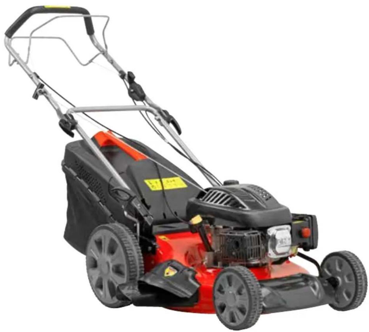
| Product Type | Lawn Mower with Wheel Drive |
| Working Width | 508 mm (20 inches) |
| Cutting Height Range | 25–85 mm |
| Cutting Height Adjustment | Central |
| Grass Catcher Capacity | 70 L |
| Drive Type | Automatic (wheel drive) |
| Number of Gears | 1 |
| Max Blade Speed | 2800 rpm |
| Sound Power Level (LwA) | 98 dB(A) |
| Engine Type | 4-stroke petrol engine |
| Oil Capacity | 0.6 L |
| Fuel Type | Petrol (gasoline) |
| Mulching Function | Yes (mulching unit included) |
| Side Discharge | Yes (side ejector outlet) |
| Safety Features | Engine control lever (dead man’s switch), deflector, grass catcher required |
| Blade Sharpening Interval | Approximately every 25 hours of use |
| Power Source | Petrol |
| Weight | Approximately 30 kg (estimated) |
Frequently Asked Questions - 721-257 Meec Tools
User questions about 721-257 Meec Tools
0 question about this device. Answer the ones you know or ask your own.
Ask a new question about this device
Download the instructions for your Lawn mower in PDF format for free! Find your manual 721-257 - Meec Tools and take your electronic device back in hand. On this page are published all the documents necessary for the use of your device. 721-257 by Meec Tools.
USER MANUAL 721-257 Meec Tools
natural_image
Red and black lawn mower with attached blue frame, no visible text or symbolsSE Bruksanvisning för gräsklippare
NO Bruksanvisning for gressklipper
PL Instrukcja obsługi kosiarka
EN Operating Instructions for Lawn Mower
SE - Bruksanvisning i original
NO - Bruksanvisning i original
EN - Operating instructions in original © Jula AB
SVENSKA....6
SÄKERHETSANVISNINGAR....6
ALLMÄNT....6
ANVÄNDNING....6
SYMBOLER 7
UNDERHÅLL OCH FÖRVARING....8
TEKNISKA DATA 9
BESKRIVNING 10
MONTERING....10
MONTERING AV GRÄSUPPSAMLARE 10
MONTERING AV HANDTAG 11
INSTÄLLNING AV KLIPPHÖJD 11
SÄKERHETSANVISNINGAR....12
HANDHAVANDE 12
START AV MOTOR 13
HJULDRIVNING 13
MULCHINGFUNKTION, SIDOUTKAST, GRÄSUPPSAMLARE 14
TIPS....14
FÖRE ANVÄNDNING 15
ANVÄNDNING AV MULCHINGFUNKTIONEN....15
ANVÄNDNING AV SIDOUTKAST 15
ANVÄNDNING AV GRÄSUPPSAMLARE 16
DEMONTERING AV MULCHINGTILLSATS. 16
DEMONTERING AV UTKASTKANAL FÖR SIDOUTKAST....16
DRIVNING 16
UNDERHÅLL 17
NORSK 19
SIKKERHETSANVISNINGER 19
GENERELT 19
BRUK....19
SYMBOLER 20
VEDLIKEHOLD OG OPPBEVARING 21
TEKNISKE DATA 22
BESKRIVELSE....23
MONTERING....23
MONTERING AV GRESSOPPSAMLER 23
MONTERING AV HÅNDTAK 24
INNSTILLING AV KLIPPEH∅YDE 24
SIKKERHETSANVISNINGER....25
BRUK....25
SAFETY INSTRUCTIONS 45
GENERAL 45
USE 45
SYMBOLS 46
MAINTENANCE AND STORAGE 47
TECHNICAL DATA 48
DESCRIPTION 49
ASSEMBLY 49
FITTING THE GRASS CATCHER 49
FITTING THE HANDLE ....50
ADJUSTING THE CUTTING HEIGHT....50
SAFETY INSTRUCTIONS....51
OPERATION....51
STARTING THE ENGINE 52
WHEEL DRIVE 52
MULCHING FUNCTION, SIDE EJECTOR, GRASS CATCHER....53
TIPS....53
BEFORE USE 54
USING THE MULCHING FUNCTION ....54
USING THE SIDE EJECTOR 54
USING THE GRASS CATCHER ....55
REMOVING THE MULCHING UNIT ....55
REMOVING THE EJECTOR OUTLET FOR THE SIDE EJECTOR ....55
DRIVE 55
MAINTENANCE 56
natural_image
Three technical line drawings of mechanical components labeled A, B, and C, showing different views and internal structures (no text or symbols beyond labels)MONTERING AV HANDTAG
natural_image
Technical line drawing of a mechanical assembly with exploded view (no text or symbols)INSTÄLLNING AV KLIPPHÖJD
natural_image
Technical line drawing of a mechanical device with labeled parts (no text or symbols present)SÄKERHETSANVISNINGAR
HANDHAVANDE
natural_image
Line drawing of a mechanical linkage or support structure (no text or symbols)MULCHINGFUNKTION, SIDOUTKAST, GRÄSUPPSAMLARE
natural_image
Mechanical assembly diagram showing a vehicle's wheel and base platform (no text or symbols)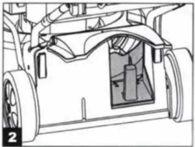
natural_image
Technical line drawing of a vehicle chassis frame with visible structural components (no text or symbols)natural_image
Diagram of a lawn mower with a mounted gear and wheel, showing mechanical components without any text or symbols.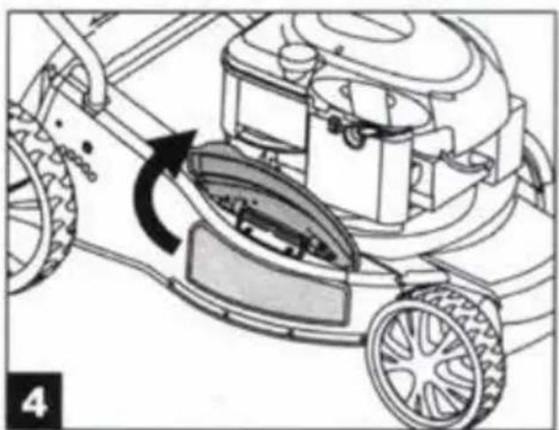
natural_image
Diagram of a lawn mower with a rotating blade and wheel, showing mechanical components without any text or symbols.natural_image
Technical illustration of a lawn mower with wheels and tire assembly (no text or symbols)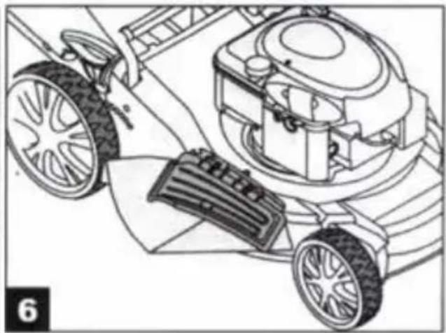
natural_image
Technical line drawing of a lawn mower with wheels and a mounted device (no text or symbols)ANVÄNDNING AV GRÄSUPPSAMLARE
DEMONTERING AV UTKASTKANAL FÖR SIDOUTKAST
natural_image
Illustration of five different mechanical or industrial components, including a tool holder, gear shift, cutting cutter, and cutting blade (no text or symbols present)natural_image
Symbol of a trash bin with no text or labels, crossed by diagonal lines and a solid black rectangle below (no readable text or symbols)Värna om miljön!
VEDLIKEHOLD OG OPPBEVARING
natural_image
Three technical line drawings of household items: a grid box, a bag, and a mobile cart with a plug (no text or symbols)MONTERING AV HÅNDTAK
natural_image
Technical line drawing of a mechanical assembly with exploded view (no text or symbols)INNSTILLING AV KLIPPEH∅YDE
natural_image
Technical line drawing of a mechanical device with labeled components (no text or symbols present)SIKKERHETSANVISNINGER
BRUK
HJULDRIFT
natural_image
Line drawing of a mechanical linkage or support structure with no visible text or symbolsnatural_image
Mechanical assembly diagram showing a vehicle chassis with a bracket and mounting base (no text or symbols)- Fell ned utkastskjermen.
natural_image
Technical line drawing of a vehicle chassis with visible structural components and mounting brackets (no text or symbols)BRUK AV SIDEUTKAST
natural_image
Mechanical diagram showing a lawn mower with a mounted gear and wheel, no text or symbols present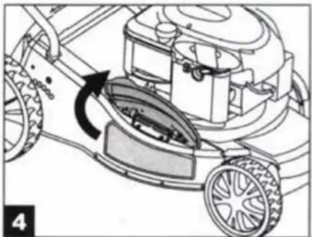
natural_image
Diagram of a lawn mower with a rotating blade and guide mechanism (no text or symbols)-
Monter utkastkanalen for sideutkast på festet til den bakre skjermen (fig. 5).
-
Fell ned den bakre skjermen slik at den dekker utkastkanalen (fig. 6).
natural_image
Technical line drawing of a lawn mower with wheels and a wheelbase, showing mechanical components without any text or symbols.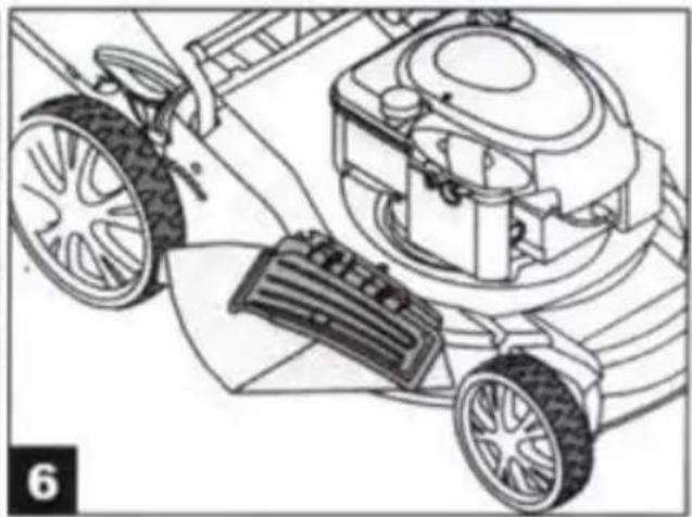
natural_image
Technical line drawing of a lawn mower system with wheels and a mounted device (no text or symbols)BRUK AV GRESSOPPSAMLER
DEMONTERING AV UTKASTKANAL FOR SIDEUTKAST
natural_image
Illustration of five different mechanical or industrial components, including a tool holder, gear shift, cutting cutter, and cleaning tool (no text or symbols present)natural_image
Symbol of a trash bin with no text or labels, including a crossed-out box and a solid black rectangle below (no readable text or symbols)Verne om miljøet!
natural_image
Three technical line drawings of household items: a grid-patterned box, a bag, and a mobile cart with wheels (no text or symbols)MONTAŻ UCHWYTU
natural_image
Technical line drawing of a mechanical assembly with exploded view (no text or symbols)REGULACJA WYSOKOŚCI KOSZENIA
natural_image
Technical line drawing of a mechanical device with labeled components (no text or symbols)ZASADY BEZPIECZEŃSTWA
OBSŁUGA
natural_image
Line drawing of a mechanical device with attached components (no text or symbols)natural_image
Illustration of a grass lawn mower with a green leaf cover and circular inset showing a green crop (no text or symbols)WSKAZÓWKI
natural_image
Technical illustration of a vehicle's front wheel assembly with a mechanical bracket (no text or symbols)natural_image
Technical line drawing of a vehicle chassis with visible structural components and mounting brackets (no text or symbols)KORZYSTANIE Z WYRZUTU BOCZNEGO
natural_image
Mechanical diagram showing a lawn mower mounted on a vehicle, with no visible text or symbols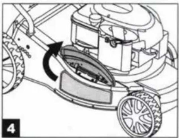
natural_image
Diagram of a lawn mower with a rotating blade and wheel, showing mechanical components without any text or symbols.natural_image
Technical line drawing of a lawn mower with wheels and a moving cart, showing no text or symbols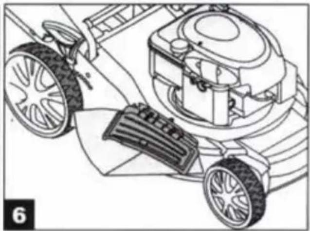
natural_image
Technical line drawing of a lawn mower system with wheels and a mounted device (no text or symbols)KORZYSTANIE ZE ZBIORNIKA NA TRAWĘ
DEMONTAŻ KANAŁU WYRZUTOWEGO WYRZUTU BOCZNEGO
natural_image
Illustration of five different mechanical or industrial components, including a tool holder, valve mechanism, cutting tool, and cleaning device (no text or symbols present)natural_image
Symbol of a trash bin with no text or labels, crossed by diagonal lines and a solid black rectangle below (no readable text or symbols)Dbaj o środowisko!
Read the instructions carefully before use.
Save these instructions for future reference.
GENERAL
- This machine is only intended for mowing lawns. Only use the machine in accordance with these instructions. All other use involves a risk of serious personal injury and/or material damage.
- Never allow children, persons with functional disorders or persons who are unfamiliar with the machine and these instructions, to use it.
- The user is responsible for any accidents or risks to other persons or property. Keep other people, especially children, and pets at a safe distance from the work area.
- Carefully inspect the area where the machine is to be used and remove any stones, wires, bones or other foreign objects. Ejected objects can cause serious personal injury.
USE
- Regularly check that all screw connections are properly tightened.
• Always check that the grass catcher, side ejector outlet or mulcher unit, is fitted. - Always check that the blade and blade screw are properly tightened. Check that the blade is sharp at regular intervals, and sharpen when necessary. Check the balance of the blade after sharpening. Replace the blade if it is damaged.
• Always wear heavy-duty shoes and long trousers when using the machine. - Never start the engine indoors or in an enclosed area. Exhaust fumes from the engine contain carbon monoxide, an odourless and highly dangerous gas – risk of serious personal injury and/or death.
- Only use the machine in daylight, or in good artificial lighting.
- Do not use the machine when it is raining, or in wet grass.
- Be very careful when changing direction, and when on slopes. Mow across slopes, never up or down.
- Do not leave the machine unattended when the engine is running. Never tilt, lift or carry the machine when the engine is running.
- Never lift or tilt the machine when starting the engine. Never put your hands or feet under the deck or in the ejector opening when the engine is running.
- The rated engine speed is set at the factory and must not be changed.
• Disengage the drive before starting. - Never lift or carry the machine when the engine is running.
- Switch off the engine and disconnect the spark plug lead from the spark plug in the following situations.
— Before doing any work under the deck or in the ejector opening.
– Before inspection, maintenance and/or repairs.
- Before tilting, lifting or carrying the machine.
– Before leaving the machine unattended. - Before adjusting the cutting height.
- Before removing the grass collector.
- Switch off the engine immediately if you hit something. Check that the machine is not damaged before starting it again. Contact an authorised service centre to have it repaired if necessary.
WARNING: The blade continues to rotate for a few seconds after the engine is switched off.
- Switch off the machine immediately in the event of abnormal noise or vibrations. Have the machine checked and repaired before using it again.
- Always check that all the screw connections are tightened and that the safety devices are properly fitted.
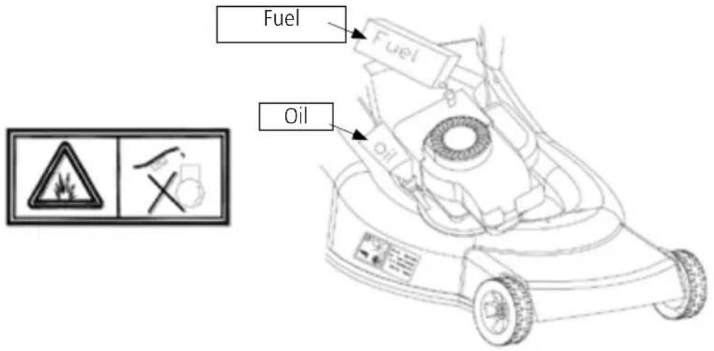
WARNING: Petrol is highly flammable and can in certain circumstances be explosive – risk of burn injuries when refuelling.
- Only store petrol in approved containers.
- Use a funnel or the equivalent when handling fuel. Work outdoors, at a safe distance from any sources of heat. Do not smoke. Do not use mobile phone.
- Always fill up with fuel and engine oil before using for the first time. Never remove the fuel cap or add fuel while the engine is running. Allow the engine to cool before filling with fuel.
- Be careful not to spill fuel when filling. Wipe up any spilled fuel immediately. Move the machine away from any fuel spill before starting.
- Replace and firmly tighten the fuel cap after filling. Replace and tighten the cap on the petrol container.
SYMBOLS
IMPORTANT: Read these instructions carefully before assembly and use.
| SYMBOL EXPLANATION | |
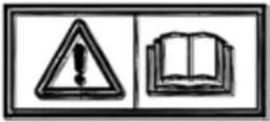 | IMPORTANT: Read these instructions before use. |
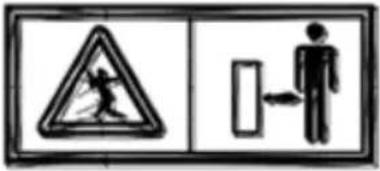 | IMPORTANT: Keep onlookers, especially children, at a safe distance from the work area. |
 | IMPORTANT: Keep your hands and feet away from moving parts – risk of serious personal injury and/or death. |
 | IMPORTANT: Only use the machine outdoors and in well-ventilated areas. |
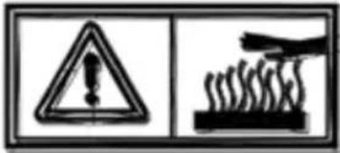 | IMPORTANT: Hot surfaces – risk of burn injuries. |
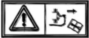 | IMPORTANT: Switch off the engine, release the spark plug lead from the spark plug, and wait until all moving parts have completely stopped before maintenance or any other work on the machine. |
 | IMPORTANT: Never refuel when the engine running. |
MAINTENANCE AND STORAGE
WARNING: Switch off the engine, release the spark plug lead from the spark plug, and wait until all moving parts have completely stopped before cleaning, maintenance and/or repairs.
- Regularly check that all screw connections are properly tightened.
- Never store the machine with fuel in the tank in areas with sources of heat, such as hot water heaters, heaters and driers etc. Allow the engine to cool before putting the machine away.
- Clean the engine and the area around the muffler and the fuel tank. Remove any residual grass and grease.
- Regularly check the deflector and grass catcher for wear or damage.
- Wear safety gloves when handling blades. Only use correctly balanced blades.
TECHNICAL DATA
Max. working width (mm) 508
| Drive | Automatic |
| Cutting height (mm) 25–85 mm | |
| Gears | 1 |
| Adjusting the cutting height Central | |
| Grass catcher volume 701 | |
| Max. blade speed (rpm) 2800 | |
| Sound power level, LwA 98 | |
| Sound pressure level, LpA | |
| Max. vibration |
Always wear ear protection.
The declared vibration value, which has been measured by a standardised test method, can be used to compare different tools with each other and for a preliminary assessment of exposure.
WARNING: The actual vibration level when using power tools may differ from the specified total value, depending on how the tool is used. It is therefore necessary to determine which safety precautions are required to protect the user, based on an estimate of exposure in actual operating conditions (taking into account all stages of the work cycle, e.g. the time when the tool is switched off and when it is idling, in addition to the start-up time).
DESCRIPTION
ASSEMBLY
FITTING THE GRASS CATCHER
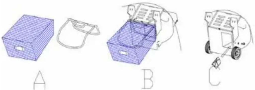
- Insert the metal frame in the grass catcher (fig. A).
- Fasten the grass catcher on the metal frame (fig. A).
- Pull up the deflector and put on the grass catcher (fig. B).
natural_image
Three technical line drawings of household items: a grid box, a bag, and a mobile cart with a plug (no text or symbols)FITTING THE HANDLE
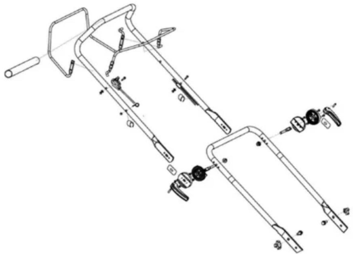
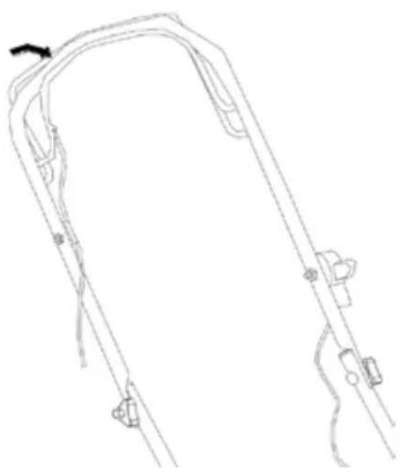
- Fold out the handle and screw the parts together with the two screws and plastic nuts.
- Hang the starter cord handle on the right-hand side of the handle and fasten the starter cord with the plastic sleeve.
- Pull the starter cord through the guide.
natural_image
Technical line drawing of a mechanical assembly with exploded view (no text or symbols)ADJUSTING THE CUTTING HEIGHT
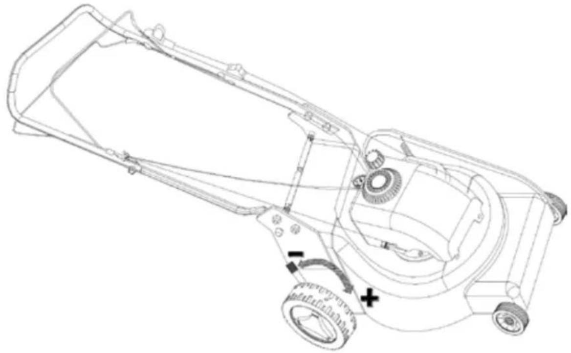
natural_image
Technical line drawing of a mechanical device with labeled parts (no text or symbols present)SAFETY INSTRUCTIONS
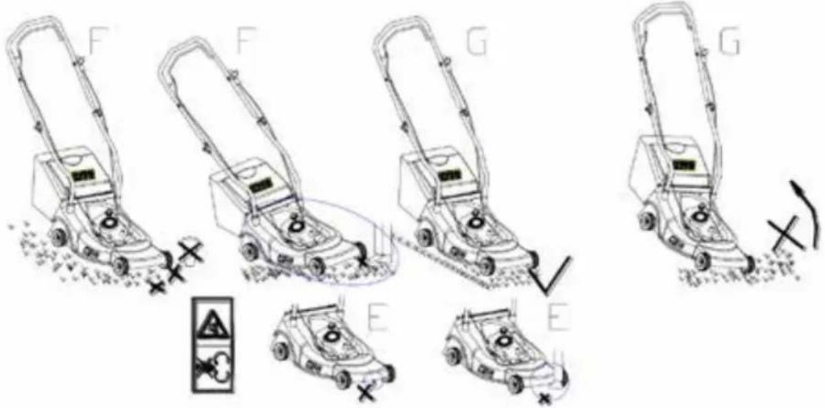
- Do not use the machine without the deflector or grass catcher.
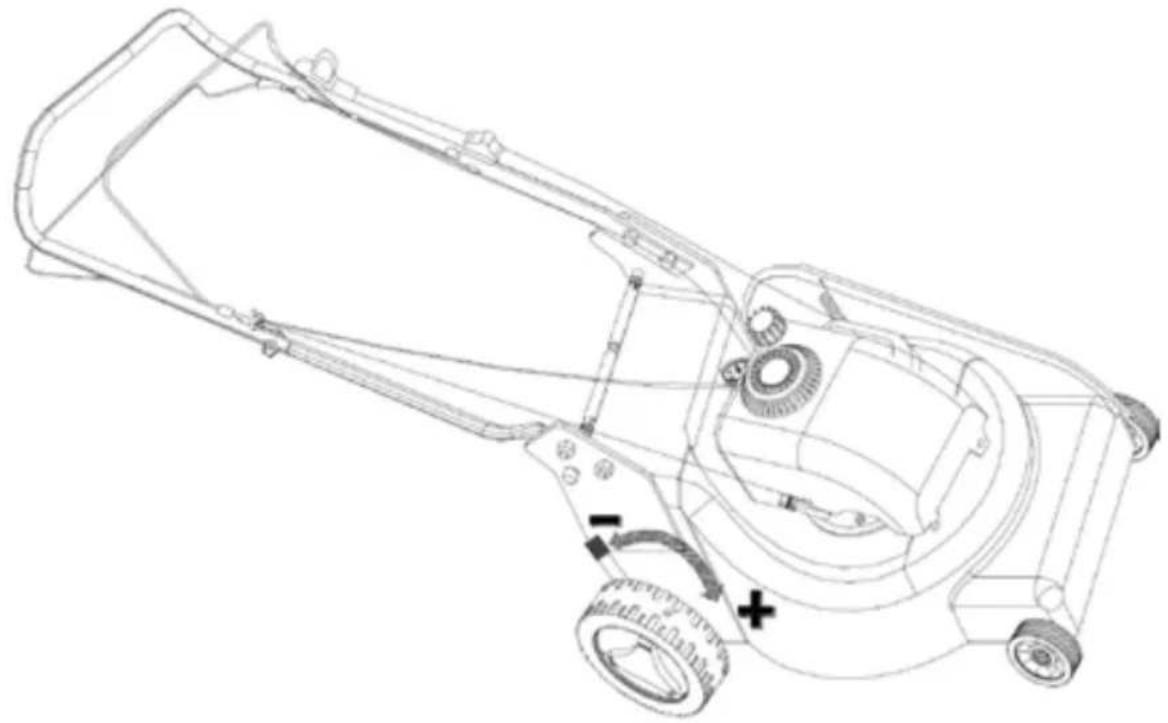
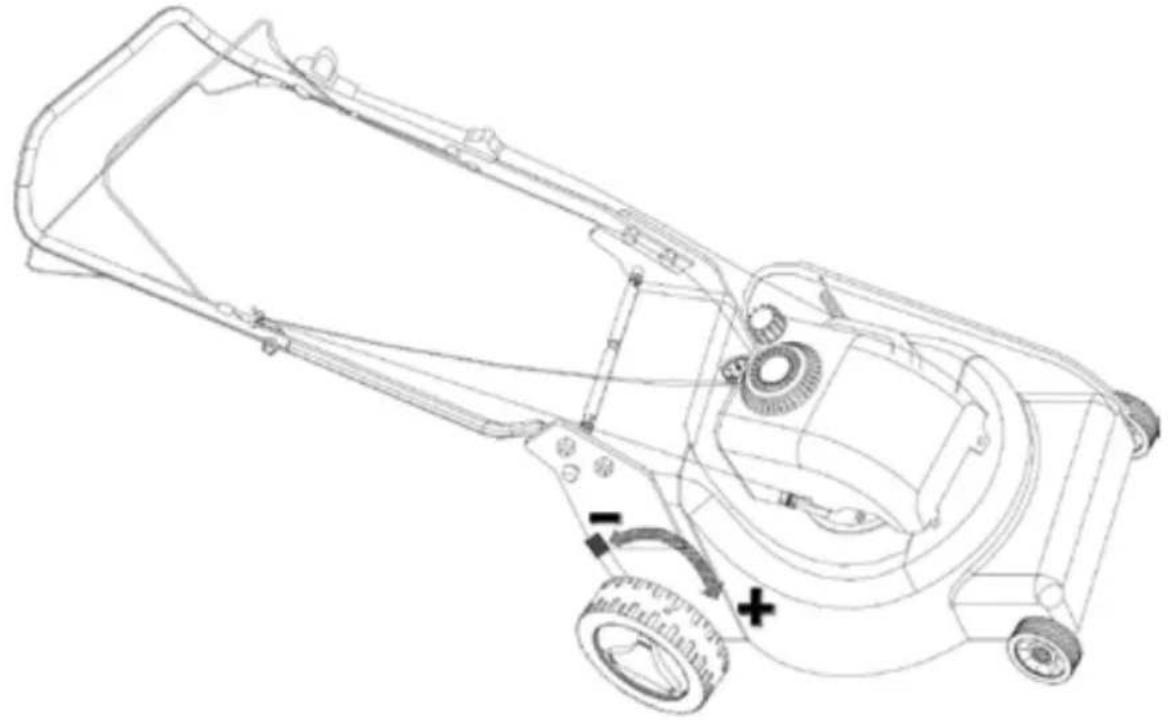
- Switch off the engine, release the spark plug lead from the spark plug, and wait until all moving parts have completely stopped before adjusting the cutting height.
- Never put your hands or feet under the deck or in the ejector opening when the engine is running (fig. E).
- Carefully inspect the area where the machine is to be used and remove any stones, wires, bones or other foreign objects (fig. F).
- Keep other people, especially children, and pets at a safe distance from the work area.
- Never lift or tilt the machine when starting the engine (fig. G).
OPERATION
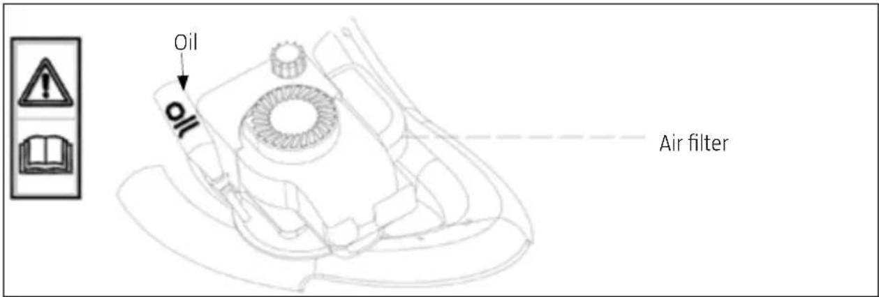
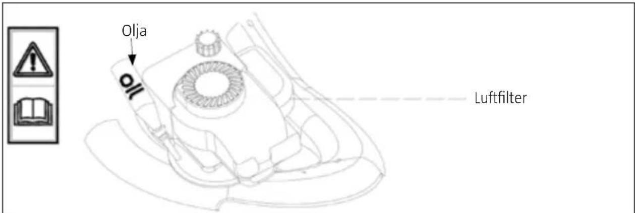
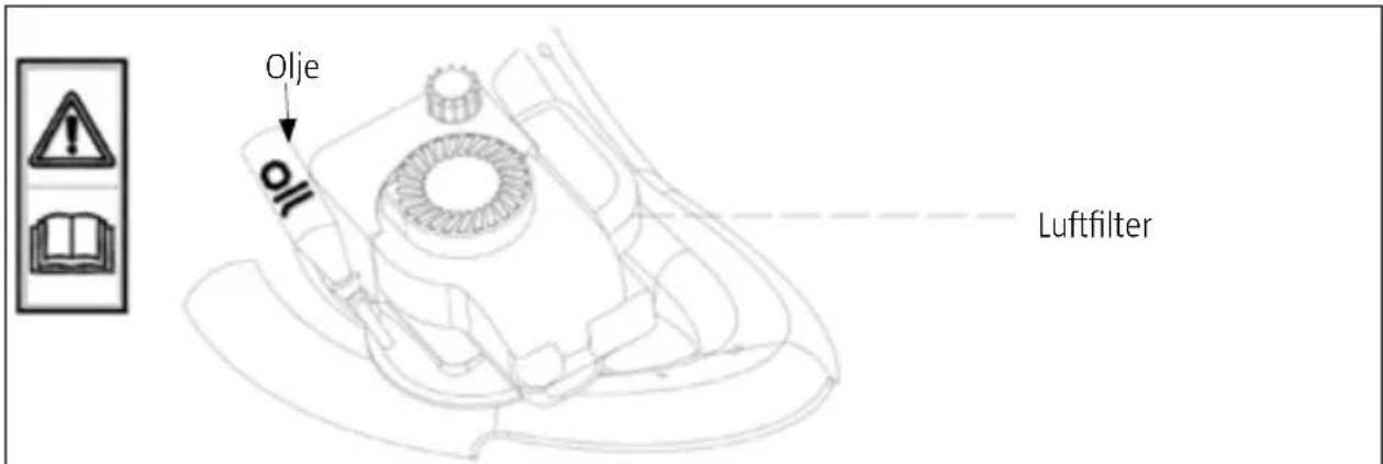
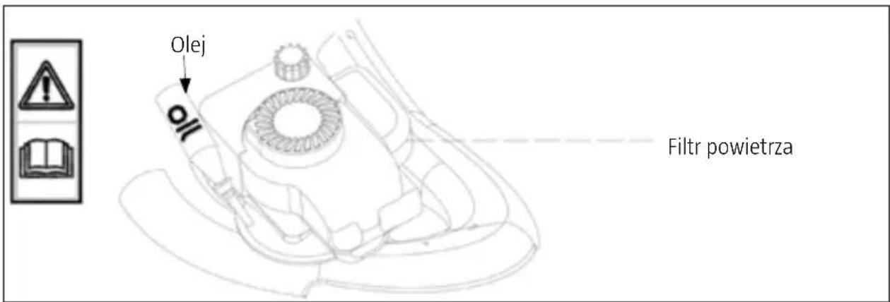
The engine is supplied without oil. Fill up with engine oil (0.6 l) before using for the first time.
STARTING THE ENGINE
- Press the fuel pump bulb 4 times.
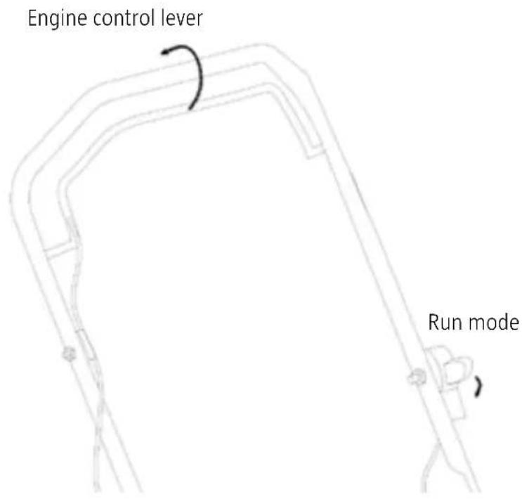
- Put the throttle control lever in the START position.
- Press the engine control lever against the handle. To start the engine, pull the starter cord slowly until it catches and then pull quickly.
- Put the throttle control lever in the RUN position.
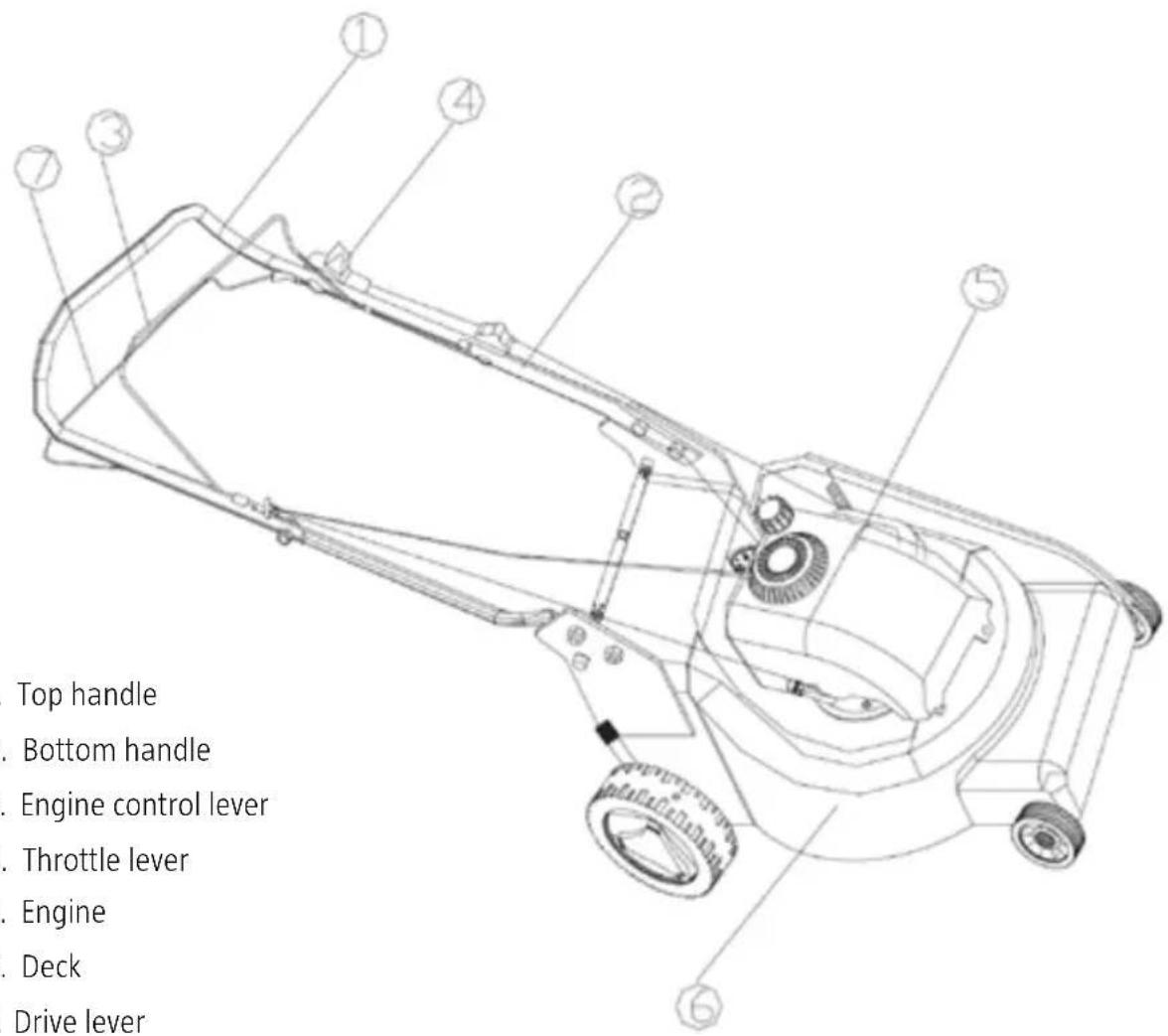
The blade starts rotating when the engine starts. Keep the engine control lever (3) pressed against the handle while working. The engine stops when the engine control lever is released.
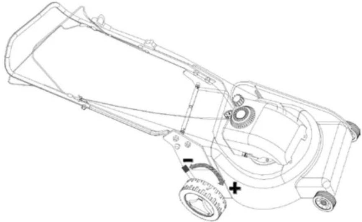
WHEEL DRIVE
Drive lever in drive mode
natural_image
Line drawing of a mechanical linkage or support structure with no visible text or symbolsStart the wheel drive by pressing the drive lever against the handle.
MULCHING FUNCTION, SIDE EJECTOR, GRASS CATCHER
The machine can be used with the mulching function, side ejector or grass catcher.
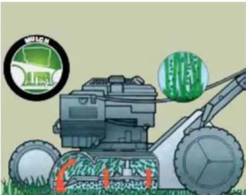
What is mulching?
Mulching means that the grass is first cut and then finely chopped before it drops down onto the lawn.
Mulching saves work.
The machine does not get as heavy when you use the mulching function and you do not need to stop to empty the grass catcher. The special blade under the arched deck chops up the grass and allows to drop onto the lawn. This means you save both time and fertiliser.
TIPS
- Cut 2 cm on a regular basis, e.g. cut 6 cm high grass down to 4 cm.
• Make sure that the blade is sharp.
- Do not cut wet grass.
• Work at full throttle.
- Walk slowly with the machine.
- Clean the mulching unit, the blade and inside of the casing at regular intervals.
BEFORE USE
NOTE: The figures refer to the illustrations.
USING THE MULCHING FUNCTION
NOTE: Switch off the engine, release the spark plug lead from the spark plug, and wait until all moving parts have completely stopped before adjusting.
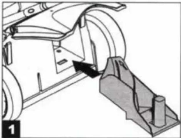
- Lift up the ejector guard and remove the grass catcher.
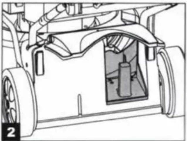
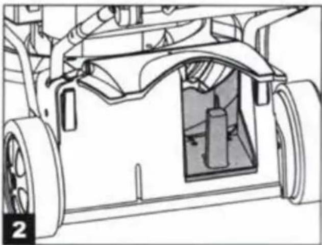
- Insert the mulching unit in the ejector opening so that it locks in place (fig. 1 and 2).
natural_image
Mechanical assembly diagram showing a vehicle's wheel and suspension mechanism (no text or symbols)- Fold down the ejector guard.
natural_image
Technical line drawing of a vehicle chassis frame with visible structural components (no text or symbols)USING THE SIDE EJECTOR
NOTE: Switch off the engine, release the spark plug lead from the spark plug, and wait until all moving parts have completely stopped before adjusting.
- Lift up the ejector guard and remove the grass catcher.
- Insert the mulching unit in the ejector opening so that it locks in place (see above).
- Lift up the guard for the side ejector (fig. 3 and 4).
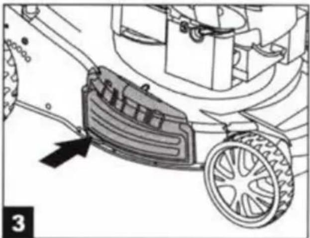
natural_image
Mechanical diagram showing a lawn mower with a mounted gear and wheel, no text or symbols present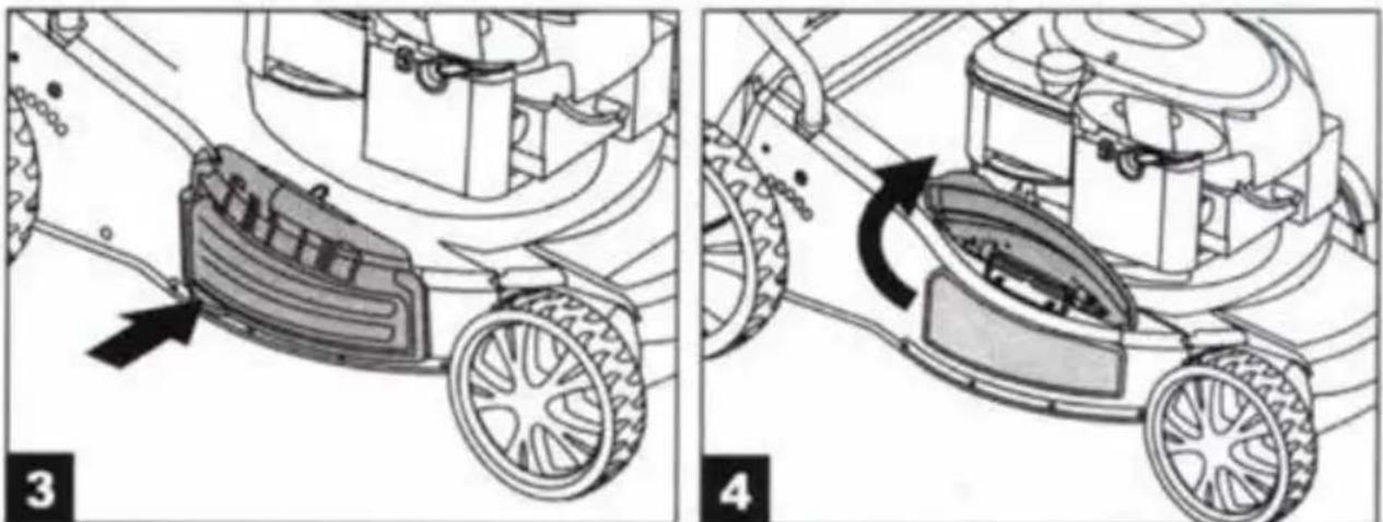
natural_image
Two-step diagram showing a lawn mower on wheels, with no text or symbols present.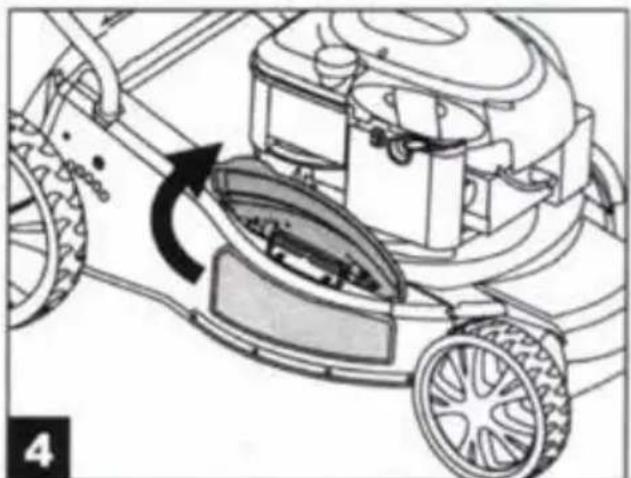
natural_image
Diagram of a lawn mower with a rotating blade and wheel, showing mechanical components without any text or symbols.-
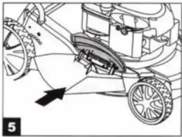
Fit the ejector outlet for the side ejector on the bracket for the rear guard (fig. 5).
-
Fold down the rear guard so that it covers the outlet (fig. 6).
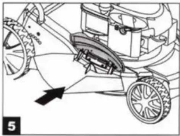
natural_image
Technical line drawing of a lawn mower with wheels and a wheelbase, showing mechanical components without any text or symbols.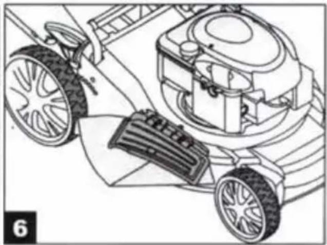
natural_image
Technical line drawing of a lawn mower system with wheels and a mounted device (no text or symbols)USING THE GRASS CATCHER
To use the grass catcher, remove the mulching unit and ejector outlet for the side ejector, and fit the grass catcher.
REMOVING THE MULCHING UNIT
Switch off the engine, release the spark plug lead from the spark plug, and wait until all moving parts have completely stopped before adjusting.
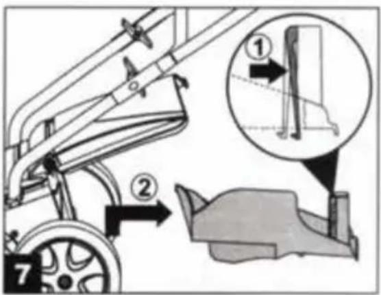
- Lift up the ejector guard
① and release and remove the mulching unit ② (fig. 7).
REMOVING THE EJECTOR OUTLET FOR THE SIDE EJECTOR
NOTE: Switch off the engine, release the spark plug lead from the spark plug, and wait until all moving parts have completely stopped before adjusting.
-
Lift it up the rear guard and remove the ejector outlet. The rear guard springs back automatically to cover the ejector opening.
-
Regularly remove grass and debris from the guard and the ejector opening.
DRIVE
- Check the drive system regularly.
- Clean och lubricate the wheel axles and bearings regularly with grease.
MAINTENANCE
WARNING: Switch off the engine, release the spark plug lead from the spark plug, and wait until all moving parts have completely stopped before cleaning, maintenance and/or repairs.
Switch off the engine, release the spark plug lead from the spark plug, and wait until all moving parts have completely stopped before cleaning, maintenance and/or repairs.
- Check the oil level regularly and top up or change the oil if necessary.
- Remove grass from underneath the deck regularly.
- Lubricate the wheel axles and bearings regularly with grease.
- Regularly check that the blade is sharp and correctly balanced.
- Regularly check that all screw connections are properly tightened. Damaged or defective screw connections can cause serious personal injury and/or material damage.
- If you run against a hard object, stop and check that the blade is not blocked or damaged. Repairs should be carried out by qualified personnel or an authorised service centre.
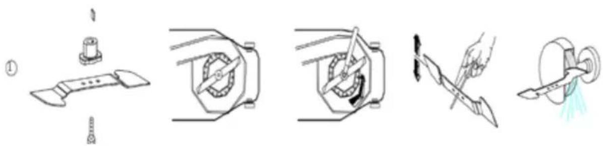
The blade should be sharpened at intervals of about 25 working hours. Check the balance of the blade by inserting a screwdriver with a round stem through the hole in the middle of the blade. The blade should hang horizontally without moving.
If the blade is unbalanced, file off some of the metal on the side of the blade that drops down.
NOTE: Only use blades recommended by the manufacturer.
Remove the blade by undoing the blade screw. Check the blade bracket and replace worn or damaged parts.
Make sure to fit the blade with the edge pointing forwards in the direction of rotation of the engine. Tighten the blade screw to 37 Nm with a torque wrench.
natural_image
Illustration of five different mechanical or industrial components, including a tool, valve, gear mechanism, and cutting tool (no text or symbols present)IMPORTANT: Only use original spare parts. The use of other parts can lead to serious personal injury or material damage.
Jula reserves the right to make changes. In the event of problems, please contact our service department. www.jula.com
natural_image
Symbol of a trash bin with no text or labels, crossed by two diagonal lines and a solid black rectangle below (no text or symbols present)Care for the environment!
Must not be discarded with household waste!
This product contains electrical or electronic components that should be recycled.
Leave the product for recycling at the designated station e.g. the local authority's recycling station.
EC DECLARATION OF CONFORMITY
EG FÖRSÄKRAN OM ÖVERENSSTÄMMELSE
EF SAMSVARSERKLÆRING
DEKLARACJA ZGODNOŚCI WE

Jula AB, Box 363, SE-532 24 SKARA, SWEDEN
certify that the design and manufacturing of this product
Machinery Directive 2006/42/EC
ISO 8437:1989+A1
Electromagnetic Compatibility Directive 2004/108/EC
EN 55012:2007+A1, EN 61000-6-1:2007
Outdoor Noise Directive 2000/14/EC, amended by 2005/88/EC
| Measured sound power level on an equipment representative for this type: Uppmätt ljudeffektnivá på en utrustning som är representativ för denna typ: Målt lydeffektnivá for utstyr som er representativt for vedkommende type: zmierzony poziom mocy akustycznej urządzenia reprezentatywnego dla danego typu: | Guaranteed sound power level: Garanterad ljudeffektnivá: Garantert lydeffektnivá: Gwarantowana moc akustyczna: | Conformity assessment procedure according to 2000/14/EC: Förfarande för bedömning av överensstämmelse enligt 2000/14/EC: Framgangsmáter for samsvarsvurdering iht. 2000/14/EC: Procedura oceny zgodności na podstawie dyrektywy 2000/14/WE: |
| 108 dB(A) 110 dB(A) | Annex V / Bilaga V Vedlegg V / Załącznik V |
This product was CE marked in year -13
Name and address of the person
Jonas Backstad
authorised to compile the technical file:
Box 363, SE-532 37 Skara, Sweden
Skara 2013-08-23

Stefan Rundberg
PRODUCT MANAGER
- SVENSKA....6
- SÄKERHETSANVISNINGAR....6
- HANDHAVANDE 12
- NORSK 19
- SIKKERHETSANVISNINGER 19
- SAFETY INSTRUCTIONS 45
- TECHNICAL DATA 48
- DESCRIPTION 49
- ASSEMBLY 49
- OPERATION....51
- MAINTENANCE 56
- MONTERING AV HANDTAG
- SÄKERHETSANVISNINGAR
- MULCHINGFUNKTION, SIDOUTKAST, GRÄSUPPSAMLARE
- ANVÄNDNING AV GRÄSUPPSAMLARE
- DEMONTERING AV UTKASTKANAL FÖR SIDOUTKAST
- Värna om miljön!
- VEDLIKEHOLD OG OPPBEVARING
- MONTERING AV HÅNDTAK
- SIKKERHETSANVISNINGER
- HJULDRIFT
- BRUK AV SIDEUTKAST
- BRUK AV GRESSOPPSAMLER
- DEMONTERING AV UTKASTKANAL FOR SIDEUTKAST
- Verne om miljøet!
- MONTAŻ UCHWYTU
- ZASADY BEZPIECZEŃSTWA
- WSKAZÓWKI
- KORZYSTANIE Z WYRZUTU BOCZNEGO
- KORZYSTANIE ZE ZBIORNIKA NA TRAWĘ
- DEMONTAŻ KANAŁU WYRZUTOWEGO WYRZUTU BOCZNEGO
- Dbaj o środowisko!
- Read the instructions carefully before use.
- GENERAL
- USE
- SYMBOLS
- MAINTENANCE AND STORAGE
- TECHNICAL DATA
- Always wear ear protection.
- DESCRIPTION
- ASSEMBLY
- FITTING THE GRASS CATCHER
- FITTING THE HANDLE
- SAFETY INSTRUCTIONS
- STARTING THE ENGINE
- WHEEL DRIVE
- MULCHING FUNCTION, SIDE EJECTOR, GRASS CATCHER
- What is mulching?
- Mulching saves work.
- TIPS
- BEFORE USE
- USING THE MULCHING FUNCTION
- USING THE SIDE EJECTOR
- USING THE GRASS CATCHER
- REMOVING THE MULCHING UNIT
- REMOVING THE EJECTOR OUTLET FOR THE SIDE EJECTOR
- DRIVE
- MAINTENANCE
- Care for the environment!
- EC DECLARATION OF CONFORMITY
- EG FÖRSÄKRAN OM ÖVERENSSTÄMMELSE
- EF SAMSVARSERKLÆRING
- DEKLARACJA ZGODNOŚCI WE
Brand : Meec Tools
Model : 721-257
Category : Lawn mower