
PI950ASIX - Hob INDESIT - Free user manual and instructions
Find the device manual for free PI950ASIX INDESIT in PDF.

| Product type | Mixed gas and electric hob |
| Brand | Indesit |
| Model | PI950ASIX |
| Dimensions (W x D x H) | 580 x 510 x 50 mm |
| Weight | 10 kg approximately |
| Power supply | Gas: G20 (natural gas) or G30/G31 (butane/propane); Electricity: 220-240 V ~ 50-60 Hz |
| Number of gas burners | 4 (1 rapid, 2 semi-rapid, 1 auxiliary) |
| Total gas power | 7.3 kW (max) |
| Number of electric plates | 1 rapid plate (optional depending on model) |
| Electric plate power | 1500 W |
| Ignition | Automatic by spark plug |
| Safety device | Safety thermocouple for gas burners |
| Surface material | Stainless steel |
| Cleaning | Clean with a damp sponge and mild detergent; do not use abrasive products |
| Spare parts | Injectors, gaskets, knobs, thermocouples available |
| Repairability | Repairability index estimated at 7/10 |
| Energy efficiency class | Not specified |
| Gas compatibility | G20, G25, G30, G31 (adaptable via injectors) |
Frequently Asked Questions - PI950ASIX INDESIT
User questions about PI950ASIX INDESIT
0 question about this device. Answer the ones you know or ask your own.
Ask a new question about this device
Download the instructions for your Hob in PDF format for free! Find your manual PI950ASIX - INDESIT and take your electronic device back in hand. On this page are published all the documents necessary for the use of your device. PI950ASIX by INDESIT.
USER MANUAL PI950ASIX INDESIT
Electrical connections
Gas connections
Data plate
Burner and nozzle specifications
Description of the appliance, 16
Overall View
Start-up and use, 17
Suggestions for using burners
Suggestions for using electric hotplates
PI 941 A
PI 941 AS
PI 950 A
PI 950 AS
Precautions and tips, 18
General safety
Disposal
Maintenance and care, 19
Disconnecting the power supply
Cleaning the appliance
Gas tap maintenance
Troubleshooting, 20
! Please keep these operating instructions for future reference. Should the appliance be sold or transferred to a new owner, or should you move house, ensure the operating instructions remain with the appliance for operation and safety information.
Please read the instructions carefully: they contain important information on installation, operation and safety.
Positioning
! Keep packaging material out of the reach of children and dispose according to the regulations on separate waste collection (see Precautions and tips).
! The appliance must be installed by a qualified professional in accordance with the instructions provided. Incorrect installation may harm people and animals or may damage property.
! The conditions relating to the adjustment procedure are listed on the label (or on the data plate).
! The appliance must be installed in ventilated rooms only and in accordance with current national legislation. The following requirements must be fulfilled:
- The room must be fitted with an air extraction system to expel combustion fumes. This may consist of a cooker hood or an electric fan which automatically activates every time the appliance is switched on.
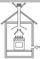
In a chimney stack or branched flue. exclusively for cooking appliances)
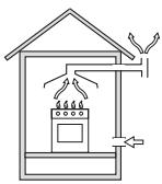
Directly to the Outside
- The room must contain a system ensuring sufficient air flow for steady combustion. The flow of air must not be less than 2m^3/h per kW of installed power.
The air flow system may take in air directly from the outside through a duct having an inner cross-section of at least 100~cm^2 ; the opening must be kept clear to avoid accidental blockages.
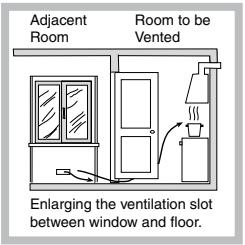
The system can also provide the air needed for combustion indirectly, i.e. from adjacent rooms fitted with air circulation ducts as described above. However, these rooms must not be common rooms, bedrooms or rooms presenting a fire hazard.
- Liquid petroleum gas sinks to the floor as it is heavier than air. Therefore, rooms containing LPG cylinders must be equipped with vents to allow gas to escape from the bottom in the event of a leak. Consequently, LPG cylinders,
whether partially or completely full, must not be installed or stored in rooms or storage areas which are below ground level (cellars, etc.). Only the cylinder currently being used should be kept in the room. It must not be exposed to direct heat sources (ovens, fireplaces, stoves, etc.) which could raise the temperature of the cylinder above 50^ .
Fitting the hob above a furniture unit
The furniture unit or any other compartment housing the hob must be appropriate in order to ensure the hob functions correctly.
The built-in hob has the following technical specifications:
- P941A-P950A: -Category II 2H3+ -Class 3 -Type Y
- P941AS-P950AS: -Category III 1a2H3+ -Class 3 -Type Y
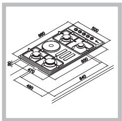
The picture shows the installation diagram with the compartment dimensions. The minimum distance between the hob and the rear wall must be at least 60~mm . If installing the hob close to corners, the minimum distance from the side wall must be at least 100~mm . Hoods must be installed according to their relative installation instruction manuals and at a minimum distance of 650~mm from the hob.
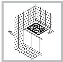
If the hob is fitted above a furniture unit with doors, the operation of the hob will not be effected by the opening and closing of the unit doors.
Fitting the hob above a furniture unit with oven
All the necessary precautions must be taken in order to install the appliance according to current accident-prevention regulations for gas and electrical connections.
To avoid overheating, the power supply cable and the gas pipe must not come into contact with the hot areas of the oven casing.
If the hob is fitted above a built-in oven without a forced ventilation cooling system, suitable air vents must be placed as shown in Fig. 8 (lower input vent of at least 200~cm^2 , upper output vent of at least 120
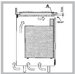
cm^2) so the inside of the furniture unit is adequate aerated (see picture).
Furthermore, a wooden board "A" must be placed beneath the hob for heat insulation. It must be at least 15 mm from the hob casing (see picture).
Fitting the hob to the worktop
The hob must be fitted to the worktop in the following manner:
- Mount the provided clamps “B” and partially tighten the screws “A” in the relative holes.
- Place the provided sealing gasket "X" 5-6 mm
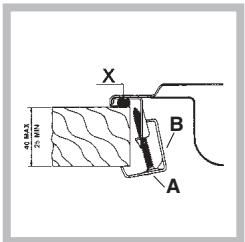
from the cut-out edge,
ensuring the ends of the seal
meet without overlapping.
- Fit the hob into the cut-out, centre it and ensure the hob edge adheres to the seal.
- Place the clamps "B" correctly and then tightly fasten the screws "A".
Electrical connections
Hobs equipped with a three-pole power supply cable are designed to operate with alternating current at the voltage and frequency indicated on the data plate (located on the underside of the hob). The earth wire in the cable has a green and yellow covering. If the hob is to be fitted above a built-in electric oven, the hob and oven electrical connections must be carried out separately, both for electrical safety purposes and to facilitate oven extraction.
Replacing the cable
Use a rubber cable of the type H05RR-F. The yellow-green earth wire must be 2-3 cm longer than the other wires.
Connecting the electricity supply cable to the mains
Mount a normalised plug corresponding to the load indicated on the data plate.
When connecting the appliance directly to the
mains, an omnipolar switch with a minimum contact opening of 3mm must be installed between the appliance and the mains. The switch should be sized for the required load and must comply with current electrical regulations (the earth wire must not be interrupted by the switch). The supply cable must be properly positioned to avoid reaching more than 50^ above room temperature, at any point along its length.
! The installer is held responsible for the correct electrical connection and for the observance of safety regulations.
Before connecting the appliance to the power supply, ensure that
- The appliance is earthed and the plug complies with regulations.
- The socket can withstand the maximum power of the appliance, which is indicated on the data plate.
- The voltage falls between the values indicated on the data plate.
- The socket is compatible with the appliance plug. If not, the socket or plug must be replaced; do not use extension cords or multiple sockets.
! Once the appliance has been installed, the power supply cable and the electrical socket must be easily accessible.
! The cable must not be subject to bending or compression.
! The cable must be checked regularly and replaced by authorised technicians only (see Assistance).
The manufacturer declines any liability should these safety measures not be observed.
Gas connections
The appliance must be connected to the main gas supply or to a gas cylinder in compliance with current national regulations. Before carrying out the connection, make sure the hob is compatible with the gas supply you wish to use. If this is not the case, follow the instructions indicated in the paragraph "Adapting to different types of gas." When using liquid gas from a cylinder, install a pressure regulator that complies with current national regulations.
! Check that the pressure of the gas supply is consistent with the values indicated in Table 1 ("Burner and nozzle specifications"). This will ensure the safe operation and longevity of your appliance while maintaining efficient energy consumption.
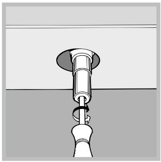
Connection with a rigid hose (copper or steel)
! Connection to the gas system must be carried out in such a way as not to place strain of any kind on the appliance.
An adjustable L-shaped pipe fitting is found on the appliance supply ramp; it is fitted with a seal in order to prevent leaks. The seal must always be replaced after rotating the pipe fitting (the seal is provided with the appliance). The gas supply pipe fitting is a threaded 1/2 gas cylindrical male attachment.
Connecting a flexible jointless stainless steel hose to a threaded attachment
The gas supply pipe fitting is a threaded 1/2 gas cylindrical male attachment.
These pipes must be installed so that they are never longer than 2000mm when fully extended. Once connection has been carried out, make sure that the flexible metal pipe does not touch any moving parts and is not compressed.
! Only use pipes and seals that comply with current national regulations.
Checking for gas tightness
! When the installation process is complete, check the pipe fittings for leaks using a soapy solution. Never use a flame.
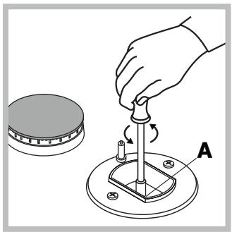
Adapting the hob to different types of gas
To adapt the hob to a different type of gas other than the default type (indicated on the data plate at the base of the hob or on the packaging), the burner nozzles should be replaced as follows:
-
Remove the hob grids and slide the burners off.
-
Unscrew the nozzles using a 7 mm socket spanner, and replace them with nozzles for the new type of gas
(see Table 1 "Burner and nozzle characteristics").
- Reassemble the parts repeating the above procedure in the reverse order.
- Replace the old rating sticker with one indicating the new type of gas used, once this procedure is completed. Stickers are available from any of our Customer Service Centres.
- Adjusting the burners' primary air:
No primary air adjusting is required.
-
Burner minimum setting
-
Turn the tap to minimum.
-
Remove the knob and turn the adjustment screw, which is in or next to the tap pin, until the flame is small but steady.
-
Check that the flame does not go out when turning the knob quickly from maximum to minimum.
- Some appliances have a safety device (thermocouple) fitted. If the device fails to work when the burners are set to minimum, increase the flame setting using the adjustment screw.
- Once the adjustment has been made, replace the seals on the by-passes using sealing wax or a similar substance.
If the appliance is connected to liquid gas, the adjustment screw must be fastened tightly.
! Once this procedure is completed, replace the old rating sticker with one indicating the new type of gas used. Stickers are available from any of our Customer Service Centres.
! Should the pressure of the gas be different (or vary slightly) from the recommended pressure, a suitable pressure regulator must be fitted to the inlet pipe (in order to comply with current national regulations).
Burner and nozzle specifications
Table 1
| Burner | Burner diameter (mm) | Thermal power kW (H.s.*) | By-pass 1/100 (mm) | Nozzle 1/100 (mm) | Flow * g/h | Nozzle 1/100 (mm) | Flow * l/h | ||
| Nomin. | Reduc. | *** | ** | ||||||
| Fast R (large) | 100 | 3.00 | 0.7 | 40 | 86 | 218 | 214 | 116 | 286 |
| Semi-Fast S (medium) | 75 | 1.65 | 0.4 | 30 | 64 | 120 | 118 | 96 | 157 |
| Auxiliary A (small) | 55 | 1.00 | 0.3 | 30 | 50 | 73 | 71 | 71 | 95 |
| Supply pressures | Minimum (mbar)Nominal (mbar)Maximum (mbar) | 302035 | 372545 | 201725 | |||||
- At 15°C and 1013 mbar - dry gas
** Propane P.C.S. = 50.37 MJ/kg
*** Butane P.C.S. = 49.47 MJ/kg
Natural P.C.S. = 37.78 MJ/m³
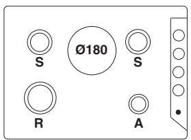
PI 941 A
PI 941 AS
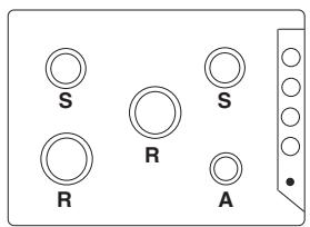
PI 950 A
PI 950 AS
| DATA PLATE | |
| Electrical connections | see data plate |
| CE | This appliance conforms to the following European Economic Community directives: -2006/95/EEC dated 12/12/06 (Low Voltage) and subsequent amendments -89/336/EEC dated 03/05/89 (Electromagnetic Compatibility) and subsequent amendments -93/68/EEC dated 22/07/93 and subsequent amendments. -90/336/EEC dated 29/06/90 (Gas) and subsequent amendments. -2002/96/EC |
Overall View
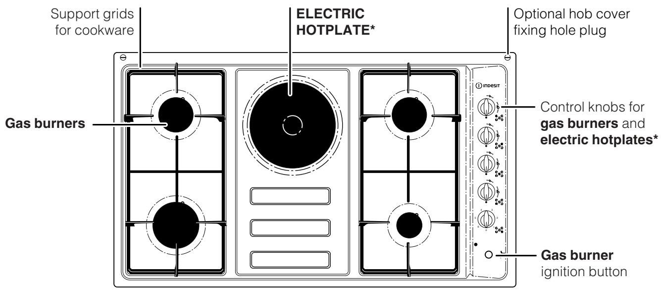
- ELECTRIC HOTPLATES come in various diameters and different power levels: "normal" or "rapid" (the latter may be distinguished from the others by a red spot in the middle of the hotplate).
- The ELECTRIC HOTPLATE INDICATOR LIGHT switches on whenever the control knob is moved from the 'off' position.
- GAS BURNERS differ in size and power. Select the most suitable burner according to the diameter of the cookware to be used.
Control knobs for GAS BURNERS and ELECTRIC HOTPLATES adjust the power or the size of the flame.
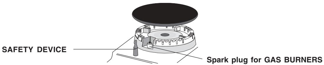
- GAS BURNER spark plug enables a specific burner to be lit automatically.
- SAFETY DEVICE* stops the gas flow if the flame accidentally dies out.
- Only available in certain models.
! The position of the corresponding gas burner or electric hotplate* is shown on every knob.
Gas burners
Each burner can be adjusted to one of the following settings using the relative control knob:
- Off

Maximum

Minimum
To light one of the burners, hold a lighted match or lighter close to the burner while pressing down and turning the corresponding knob anti-clockwise to the maximum power setting.
In those models fitted with a safety device, the knob should be pressed for approximately 6 seconds so the automatic device keeping the flame alight can heat up.
When using models equipped with spark plugs, light the desired burner by first pressing the gas burners button (marked by the symbol XXX), then pressing down the corresponding knob while turning it anti-clockwise towards the maximum power setting.
! If the flame accidentally dies out, turn off the control knob and wait at least 1 minute before trying to relight it.
To switch off the burner, turn the knob in a clockwise direction until it stops (position marked by the “ ” symbol).
Electric hotplates*
The corresponding knob may be turned clockwise or anti-clockwise and set to six different positions:
| Setting | Normal or Fast Plate |
| 0 | Off |
| 1 | Low |
| 2 - 5 | Medium |
| 6 | High |
When the control knob is in any position other than the 'off' position, the indicator light is illuminated.
* Only available in certain models.
Suggestions for using burners
For maximum burner efficiency
- Use appropriate cookware for each burner (see table below) so that the flames do not extend beyond the bottom of the cookware.
Always use cookware with a flat base and a cover. - Turn the knob to the minimum power setting when the contents of the pan reach boiling point.
| Burner | Ø Cookware diameter (cm) |
| Fast (R) | 24 - 26 |
| Semi Fast (S) | 16 - 22 |
| Auxiliary (A) | 10 - 14 |
The reducer shelf (where present), must only be used for the auxiliary burner.
! Make sure the pans do not overlap the edges of the hob while it is being used.
To identify the type of burner, please refer to the diagrams contained in the paragraph "Burner and nozzle specifications."
Suggestions for using electric hotplates*
To avoid heat loss and damage to the hotplates, use pans with a flat base and a diameter never smaller than that of the hotplate.
| Setting | Normal or Fast Plate |
| 0 | Off |
| 1 | Cooking vegetables, fish |
| 2 | Cooking potatoes (using steam) soups, chickpeas, beans. |
| 3 | Continuing the cooking of large quantities of food, minestrone |
| 4 | For roasting (average) |
| 5 | For roasting (above average) |
| 6 | For browning and reaching a boil in a short time. |
! Before using the hotplates for the first time, they should be heated at maximum temperature for approximately 4 minutes, without placing any pans on them. During this initial stage, their protective coating hardens and reaches its maximum resistance.
! This appliance has been designed and manufactured in compliance with international safety standards. The following warnings are provided for safety reasons and must be read carefully.
General safety
- This is a class 3 built-in appliance.
- Gas appliances require regular air exchange to maintain efficient operation. When installing the hob, follow the necessary requirements contained in the paragraph entitled "Positioning".
- These instructions are only valid for those countries whose symbols appear in the manual and on the serial number plate.
- The appliance is designed for domestic use inside the home and not for commercial or industrial use.
- The appliance must not be installed outdoors, even in covered areas. It is extremely dangerous to leave the appliance exposed to rain and storms.
- When handling the appliance, always use the handles provided on the sides of the hob.
- Do not touch the appliance when barefoot or with wet or damp hands and feet.
- The appliance must be used by adults only for the preparation of food, in accordance with the instructions provided in this booklet.
- Make sure that the power supply cables of other electrical appliances do not come into contact with the hot parts of the hob.
- The air circulation and heat dispersion vents must never be covered.
Always make sure the knobs are in the "●"/"O" position when the appliance is not in use. - When unplugging the appliance, always pull from the plug, never from the cable.
-
Never perform any cleaning or maintenance work without having previously disconnected the appliance from the electricity mains.
-
If the appliance breaks down, under no circumstances should you attempt to perform the repairs yourself by accessing the internal mechanism. Contact a Customer Service Centre (see Assistance).
- Always make sure that pan handles are turned towards the centre of the hob in order to avoid accidentally knocking the pans over.
- Do not close the glass cover (if present) while the gas burners or electric hotplates are still hot.
- Do not leave the electric hotplate switched on without a pan placed on it.
- Do not use unstable or warped pans.
- The appliance is not intended for use by people (including children) with reduced physical, sensory or mental capacities or by those unfamiliar or inexperienced with the appliance, unless adequately supervised by a person in charge of their safety or unless they have been supplied with preliminary instructions regarding appliance use.
- Do not let children play with the appliance.
- Intensive and prolonged operation of the appliance may require additional ventilation, for example a window should be opened or more efficient ventilation provided (the power of any mechanical ventilation system could be increased, for instance).
Disposal
- When disposing of packaging material: observe local regulations so that the packaging may be reused.
- The European Directive 2002/96/EC relating to Waste Electrical and Electronic Equipment (WEEE) states that household appliances should not be disposed of using the normal solid urban waste cycle. Appliances no longer in use should be collected separately for optimal recycling and reusing of materials and to prevent potential health and environmental hazards. The crossed-out dustbin symbol is placed on all products as a reminder of our obligation regarding separate waste collection. For further information regarding the correct disposal of household appliances, owners may contact public service agencies or their local dealer.
Disconnecting the power supply
Disconnect the appliance from the electricity supply before carrying out any work on it.
Cleaning the appliance
! Avoid using abrasive or corrosive detergents such as stain removers or rust inhibitors, powder detergents or sponges with an abrasive surface: these may scratch the hob surface beyond repair.
! Never use steam cleaners or high-pressure cleaners on the appliance.
- Cleaning the hob with a damp sponge and drying with kitchen paper is sufficient for ordinary cleaning purposes.
- The removable parts of the burner should be washed regularly with warm water and soap, ensuring any stubborn residue is removed.
- For hobs that light automatically, clean the terminal part of the instant electronic ignition device thoroughly and regularly and check that the gas outlet holes are not clogged.
- Electric hotplates should be cleaned with a damp cloth and lubricated with a little oil while still warm.
- Stainless steel may tarnish as a result of prolonged contact with very hard water or aggressive detergents containing phosphorus. After cleaning, rinse well and dry thoroughly. Dry-off any remaining drops of water.
Gas tap maintenance
Over time, gas taps may jam or become difficult to turn. If this occurs, they must be replaced.
! This procedure must be carried out by a technician authorised by the manufacturer.
If the appliance does not function properly or at all, carry out the following inspections before calling the Customer Service Centre for assistance. Check for any interruptions in the gas or electricity supply lines. In particular, check whether the gas taps for the mains supply are open.
The burner does not switch on or the flame is not steady.
Check whether
- The gas outlet holes on the burner are clogged.
- The removable parts of the burner are correctly fitted.
- Draughts occur near the appliance.
The flame does not continue to burn in the versions with safety device.
Check whether
- The knob is pressed all the way in.
- The knob is pressed long enough to activate the safety device.
- The gas holes are blocked in the area corresponding to the safety device.
The burner does not remain lighted with the minimum setting.
Check whether
- The gas outlet holes are clogged.
- Draughts occur near the appliance.
- The minimum setting has been properly adjusted.
The cookware is unstable.
Check whether
- The bottom of the cookware is perfectly flat.
- The cookware is correctly positioned in the centre of the burner or hotplate.
- The hob grids have been correctly positioned.
If, despite all the checks, the hob does not function properly and the problem persists, please contact the Customer Service Centre. Please have the following information on hand:
- The appliance model (Mod.).
The serial number (S/N).
This information can be found on the data plate located on the appliance and/or on the packaging.
! Never use the services of unauthorised technicians and never accept spare parts which are not original.

Italiano, 1

English, 11

Français, 21

Espanol, 31

Portuges, 41

Nederland, 51
Sommaire
Installation, 22-25
Positionnement