
EFV 3260-90 X - Range hood GRAM - Free user manual and instructions
Find the device manual for free EFV 3260-90 X GRAM in PDF.

| Product Type | Kitchen extractor hood (range hood) |
| Model | EFV 3260-90 X |
| Brand | Gram |
| Width (cm) | 59.8 |
| Depth (cm) | 50 |
| Height (cm) | Min. 60 / Max. 95 |
| Net Weight (kg) | 3.1 |
| Power Supply | 240V 1N~50Hz |
| Power Consumption (W) | 285 |
| Motor Power (W) | 285 |
| Number of Speeds | 3 |
| Maximum Airflow (m³/h) | 500 |
| Noise Level (dBA) | 52.3 |
| Air Outlet Diameter (mm) | 120 / 150 |
| Lighting Power (W) | 2 x 50 (halogen) |
| Grease Filters | 2 aluminum cassette filters |
| Carbon Filter | Optional (active carbon, replaceable) |
| Control Type | Electronic push-button with 3-speed digital control and auto-timer |
| Operation Modes | Extractor (external ducting) or recirculation (with carbon filter) |
| Mounting Type | Wall-mounted with telescopic chimney |
| Minimum Distance from Hob (mm) | 650 (or as per hob manual) |
| Electric Shock Class | Class I |
| Color/Finish | Stainless steel INOX |
| Compliance | Low Voltage Directive 2006/95/EC, EMC 2004/108/EC, ErP 2009/125/EC |
| Warranty | Standard manufacturer warranty (details in manual) |
| Included Accessories | L-shaped mounting brackets, plastic duct, screws, wall plugs, lower & upper duct enclosures, aluminum flexible duct (not specified if included, check package) |
Frequently Asked Questions - EFV 3260-90 X GRAM
User questions about EFV 3260-90 X GRAM
0 question about this device. Answer the ones you know or ask your own.
Ask a new question about this device
Download the instructions for your Range hood in PDF format for free! Find your manual EFV 3260-90 X - GRAM and take your electronic device back in hand. On this page are published all the documents necessary for the use of your device. EFV 3260-90 X by GRAM.
USER MANUAL EFV 3260-90 X GRAM
You are now a user of a kitchen extractor hood. This hood has been designed and manufactured specially with a view to satisfying your expectations and it will certainly constitute a fitting element of a modern kitchen. The modern structural solutions and the newest technologies used in production of this hood guarantee its high effectiveness and good appearance. Please read these instructions carefully before installing the hood. They will help you avoid mistakes during installation and operation of the hood.
DK
I GENERELLE OPLYSNINGER 8
II KOMPONENTER 8
III TEKNISKE DATA 8
IV DRIFT 9
V MONTAGE 10
VI BETJENING OG VEDLIGEHOLDELSE 12
FI
I YLEISTÄ TIETOA 15
II KOMPONENTIT 15
III TEKNISET TIEDOT 15
IV KÄYTTÖ 16
VASENNUS 17
VI KÄYTTÖ JA HUOLTO 19
VII HÄVITTÄMINEN 21
NO
I GENERELLE OPPLYSNINGER 22
II KOMPONENTER 22
III TEKNISKE DATA 22
IV DRIFT 23
V MONTERING 24
VI BETJENING OG VEDLIKEHOLD 26
VII KASSERING 28
SE
I GENERELLA UPPLYSNINGAR 29
II DELAR 29
III TEKNISKA DATA 29
IV ANVÄNDNING 30
V MONTERING 31
VI ANVÄNDNING OCH UNDERHÅLL 33
VII AVFALLSHANTERING 35
EN
I CHARACTERISTICS 36
II COMPONENTS 36
III TECHNICAL DATA 36
IV OPERATING CONDITIONS 37
V INSTALLATION 38
natural_image
Technical line drawing of a mechanical assembly with a cylindrical component mounted on a base plate, labeled '3j' (no text or symbols on the diagram itself)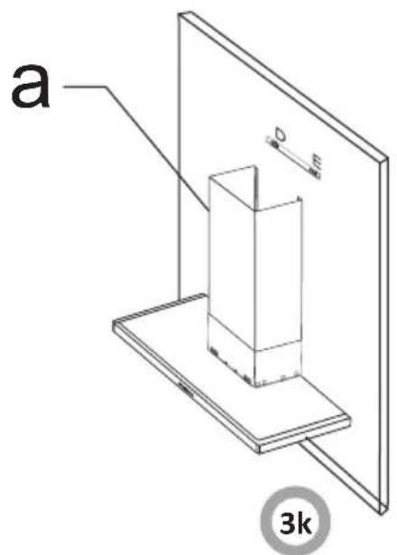
natural_image
Two-panel image showing a flexible pipe with coiled insulation, one crossed out by a red X symbol (no text or symbols present)
natural_image
Technical diagram of an air duct system with fan components and directional arrows indicating rotation (no text or labels)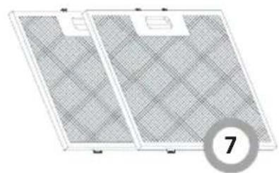
natural_image
Two rectangular panels with grid patterns, one labeled with number 7 (no text or symbols on panels)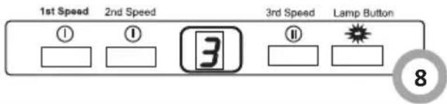
natural_image
Simple line drawing of a recycling symbol (three chasing arrows), no text or labels present.natural_image
Simple line drawing of a trash bin with crossed lines indicating no waste or plastic (no text or symbols)
natural_image
Simple line drawing of a recycling symbol (three chasing arrows), no text or labels present.natural_image
Symbol of a trash bin crossed with a diagonal line, representing waste or discharge (no text or labels)
natural_image
Simple line drawing of a recycling symbol (three chasing arrows), no text or labels present.Obs! Emballasjematerialet (polyetylenposer, isoporbiter ol.) skal holdes unna barn under utpakking.
ANBEFALINGER:
natural_image
Symbol of a trash bin crossed with two crossed lines and a solid black rectangle below (no text or labels)natural_image
Simple line drawing of a recycling symbol (three chasing arrows), no text or labels present.natural_image
Symbol of a trash bin crossed with diagonal lines and a horizontal bar below (no text or labels)This kitchen extractor hood was designed to remove or neutralize kitchen fumes. It has to be installed permanently over a gas or electric cooker. It requires installation of a conduit discharging used air to the outside if working in fume removal mode. The conduit (a pipe ∅120 mm) shall not be longer than 4-5 m. The hood can operate as an odour absorber after installation of an active carbon filter. In such case a conduit discharging used air to the outside is not necessary. The kitchen hood is an electrical appliance manufactured according to class II of fire protection, equipped with a permanent supply cord and plug. It has its own lighting and an exhaust fan which can be set to one of three rotational speeds.
II COMPONENTS
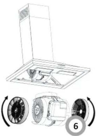
kitchen hood consists of the following elements (Fig. 1):
- Internal Chimney
- External Chimney
- Control Panel
- Cooker Lighting
- Aluminum Cassette Filter
- Tempered Glass
III TECHNICAL DATA
| Hood type | EFV 3460-90 X EFV 3490-90 X EFV 3250-90 X EFV 3260-90 X EFV 3290-90 X | ||||
| Power supply voltage | 240V 1N~50Hz 240V 1N~50Hz 240V 1N~50Hz 240V 1N~50Hz | ||||
| Fan motor | 1 1 1 1 1 | ||||
| Lighting | 2x50 2x50 2x50 2x50 2x50 | ||||
| Number of grease filters | 2 3 1 2 2 | ||||
| Number of speeds | 3 3 3 3 3 | ||||
| Width (cm) | 59,8 89,8 49,8 59,8 89,8 | ||||
| Depth (cm) | 50 50 50 50 50 | ||||
| Height (cm) | min.63,5max.101,5 | min.63,5max.101,5 | min.60max.95 | min.60max.95 | min.60max.95 |
| Air outlet (ø mm) | 120 / 150 120 / 150 120 / 150 120 / 150 | ||||
| Capacity (m3/h) | 500 500 500 500 500 | ||||
| Power consumption (W) | 285 285 285 285 285 | ||||
| Noise level (dBA) | 52,3 52,3 52,3 52,3 52,3 | ||||
| Net weight (kg) | 12,7 14,6 12,6 3,1 15,8 | ||||
| electric shock class | 11111 | ||||
| Work | Extract or absorb | Extract or absorb | Extract or absorb | Extract or absorb | Extract or absorb |
| Color | Stainless steel INOX | Stainless steel INOX | Stainless steel INOX | Stainless steel INOX | Stainless steel INOX |
- The kitchen hood was designed for removal of kitchen fumes to the outside. It should be connected to an appropriate ventilation duct (do not connect the hood to any chimney, smoke or flue-gas ducts which are in use).
- The safe distance between a cooker and the hood should be at least 650 mm. If a cooker manual specifies other distance, this should be taken into account (fig. 2).
- Do not leave open flame under the hood. When removing pots from the burners set the flame to its minimum level.
- Any food cooked in fat shall be constantly monitored, since overheated fat can ignite very easily.
- The textile grease filter should be replaced, and the aluminium filter should be cleaned at least every 2 months in connection with the existing fire danger (saturated fat is very flammable).
- Pull the plug of the power cord from a wall socket before any filter cleaning or repair operation.
- If any other non-electric devices are used in the same room as the hood (e.g. liquid fuel ovens, flow-through or volumetric water heaters), it is necessary to provide appropriate ventilation (air supply). Safe operation is possible when during simultaneous operation of the hood and combustion devices dependent on air supply the negative pressure of not more than 0.004 milibar is maintained at the location of these devices inside the room (this point does not apply when the hood is used as an odour absorber).
- When connecting to 240V power supply network use an electric socket in working order.
- Do not lean on the hood
- Hood should be cleaned once per month - see point „Cleaning” in this manual.
- If the power wire gets broken, it should be replaced with a new one in a specialist repair shop.
- Some parts of the hood become hot when the appliance is operating.
This appliance is designed for household use only. The manufacturer reserves the right to introduce changes which do not affect the operation of the appliance.
UNPACKING
The device was protected against damage for the time of transport. After unpacking, please remove the elements of packaging in an environment-friendly way. All materials used for packaging are environment friendly, they can be 100% recycled and they have been marked with appropriate symbols.

natural_image
Simple line drawing of a recycling symbol (three chasing arrows), no text or labels present.Warning! The packaging materials (polyethylene bags, small pieces of foamed polystyrene etc.) should be kept away from children while unpacking.
RECOMMENDATIONS
- before you connect the hood to the power supply and check whether it works properly, you will always need to control if the wire has been properly installed and if it has NOT been pinned down by the hood while it was being mounted.
- This appliance is not intended for use by persons (including children) with limited physical or mental capabilities and persons who lack experience or familiarity with the appliance.
Do not allow unattended children to use the appliance. Do not allow them to play with the appliance.

NOTE: The manufacturer will accept no responsibility for any damage due to installation or operation not conforming to these instructions
Installation, unpacking the product:
- Check if there is any damage to the product.
●Transportation damage should be immediately reported to the shipping company. - If you notice any damage please report to the seller.
- Do not allow children to play with packing material!!!
Installing the support bracket
There are 2 L shaped support brackets to install your product, provided with screws. Fix brackets on the product body using M5 x 35 screws into M5 turn screws (figure 3a).
a) M5 x 35 YSB
b) L shaped support brackets
Install plastic duct
Mount plastic duct on top of motor compartment using 3,5x9,5 screws (figure 3b).
Drill mounting holes ∅ 6 mm
Attach mounting template on the wall and drill holes at points marked as A,B,C using 8 mm drill bit. To install enclosure, use driller by taking reference of min./max. height dimensions (figure 3c).
WARNING : During drilling of the hanging holes, pay attention to the diameter of the holes to be used for hanging the hood. If the diameters of hanging holes are not as indicated, the hood cannot be assembled properly.
Wall plugs
Drive 10 mm wall plugs into 8 mm A,B,C holes. Place 6 mm wall plug in two 6 mm holes (Figure 3d). Drill holes at points marked as G,H and drive 10 mm wall plugs in them.
a) 10 mm Plastic wall plug
b) 6 mm Plastic wall plug
c) Outlet Connection Holes ∅ 6 mm
d) Hood hanging holes ∅ 8 mm
Enclosure support bracket screws;
Drill holes in the wall using a ∅6 mm drill-bit. Fix the enclosure support bracket using 3,9 x 22 Ysb screws and ∅6 mm plastic wall plugs. Drill holes in the wall using a ∅10 mm drill-bit. Fix 2 pcs of 5,5 x 60 Ysb screws at A,B points in ∅10 mm plastic wall plugs. The screws should protrude from the wall about 5 mm (Figure 3e).
a) 5,5 x 60 Ysb Screw
b) 3,9 x 22 Ysb Screw
Placing cooker hood on the wall
Hang L shaped support brackets on A and B points (figure 3f)
Tighten the hanging screws:
Using a screwdriver tighten screws to fix the product. You may use the M5x40Ysb screws to make fine adjustment of hood parallel alignment (figure 3g).
Note: You may make fine adjustments to parallel alignment by easing M5 screws on the top.
Tighten the Hanging Screws:
Fix product onto wall at point C with 5,5x60 Ysb screw in order to ensure your product is safely installed (figure 3h).
Fix product onto wall at point G,H with 5,5x60 screws in order to ensure your product is safely installed (figure 3i)
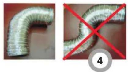
Installing aluminium flexible duct:
Connect aluminium flexible duct to outlets on the product and kitchen wall.
Please make sure that this connection is strong enough not to break when the hood operates at highest fan speed (figure 3j).
Installing the lower duct enclosure:
Place upper enclosure onto lower enclosure. Place enclosure onto motor box and push it downward.
Make sure that the connection between the body and motor box is tight (figure 3k).
a) Lower duct enclosure
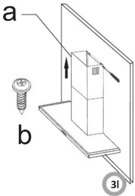
Installing the upper duct enclosure:
Push upper enclosure up through the lower enclosure. Fix the enclosure with 3,5 x 9,5 nickel covered screws (figure 3I).
a) Upper duct enclosure
b) 3,5 x 9,5 RYSB Nickel Screw
When hood installation is complete, check all the connections before turning it on. Please take off the protective film from your product.
Connecting to the power network and operation check
After connecting the device to the power supply network (in accordance with the requirements defined above) it is necessary to check operation of the motor and lighting of the hood.
Setting the operation mode of the kitchen extractor hood
Setting the air extractor mode of operation of the hood
In the extractor mode air is discharged to the outside by a special conduit. In that setting any carbon filters shall be removed. The hood should be connected to the opening discharging air to the outside by means of a rigid or flexible conduit of 120 mm diameter, which should be purchased in a shop selling installation materials.
A qualified installer should be commissioned to make the connection.
Setting the odour absorber mode of operation of the hood
In this option filtered air returns to the room through openings in the front of the hood. In this setting it is necessary to install the carbon filter.
Fan speeds
The lowest and medium speeds should be used under normal conditions and with low concentration of fumes. The top speed should be used in case of high concentration of kitchen fumes, e.g. during frying or grilling.
1. Operational safety.
All safety instructions included in chapter IV must be observed. Textile grease filters and carbon filters should be replaced and aluminium filter should be cleaned according to manufacturer's instructions, or more frequently in periods of intensive use (more than 4 hours a day). If a gas cooker is used it is forbidden to leave uncovered flame. When removing pots from gas burners set the flame to its minimum level. Always make sure that flame does not extend outside the pot. Such a situation causes undesired energy losses and dangerous heat build-ups. The hood should not be used for other purposes than those for which it was designed.
2. Operation:
2.1 Control panel (fig. 8)
Using the 3-speed digital control
Peel off protective film from the inox appliance after assembly.
Speed choice
The appliance has 3 fan speeds. Depending on cooking intensity and the amount of steam, you can choose low, medium or high fan speed. Buttons on the front panel are used for turning the appliance on. The models with electronic controllers have an automatic timer. 15 minutes automatic timer is turned on when you press any of the buttons, which starts the motor up, more than 2 seconds. When timer starts, display will indicate the function is on and after 15 minutes motor will automatically stop. Please turn on hob and hood at the same time to provide effective circulation. Allow the appliance to run for a while after cooking is finished, so the remaining odour and steam will be absorbed.
2.2 Lighting
The product has 2 lamps and one lamp button to operate light. Press lamp button in order to turn on the light.
Aluminium filter cleaning
Filter should be cleaned when “C” indication appears on the display or every 2-3 weeks (depending on usage intensity). After cleaning and replacing filters, press the ① button for more than 3 seconds (when the product is off) in order for the “C” indication to disappear. “E” indication will appear on display and product will start operating normally. If you want to continue using your product without removing the “C” indication, active speed will appear for 1 second when you press ② button, then “C” indication appears once more and the motor will continue operating.
3. Maintenance.
Regular maintenance and cleaning of the device will guarantee its good and fault-less operation, and extend its life. Attention should be paid to replacing grease and carbon filters according to instructions.
3.1 Grease filter
- Cleaning.
Grease filters should be cleaned every two months during normal operation of the hood,
in a dishwasher or manually, using mild detergent or liquid soap. - Replacement (Fig. 7).
To dismantle the filter proceed as follows:
a) remove the bottom cover by releasing the lock catch
b) remove the metal grease filter
3.2. Carbon filter
Carbon filters can be used only when the hood is not connected to any ventilation duct.
Filters with active carbon can absorb odours until they are saturated. They cannot be washed or regenerated and should be replaced at least every 2 months or more frequently in case of very intensive use.
- Active carbon filter replacement.
a) Remove metal grease filter
b) Put a new active carbon filter on the motor block (fig. 6)
c) Replace the metal grease filter
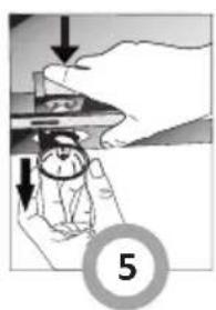
3.3. Lighting (fig. 5)
Unplug the appliance. Take off the aluminium cassette filter.
Remove the defective lamp and replace it with a new one that is of the same rating. (Please wait for the lamps to cool as they might scald your hand.)
Replacing 50W Halogen Lamp
In order to change halogen lamps, pull the lamp down pushing back the lamp holder downwards and then turn it a little bit anti-clockwise and remove it.
3.4. Cleaning
The following shall be avoided during normal cleaning of the hood:
- wet cloth or sponge and water jet,
●solvents or alcohols which might dull lacquered surfaces,
●caustic agents, particularly in regard to cleaning stainless steel elements, - hard, rough cloth
It is recommended to us moist cloth and neutral cleaning agents.
Aluminium filters may be washed in the dishwasher. Colour of aluminium filters may change after several washings. This is normal and it is not necessary to change the filters.
When disposing of the device, do not bring it to regular municipal waste containers. Instead, bring it to electrical and electronic waste recycling and reuse center. A relevant label has been put on the device, its instructions manual, or on the package.
The device has been manufactured of recyclable materials. By bringing old device to recycling collection center, you show that you care about nature.
Ask your local environmental care authority for information on location of such facilities.
natural_image
Symbol of a trash bin crossed with diagonal lines and a horizontal bar below (no text or labels)Manufacturer's Declaration
The manufacturer hereby declares that this product meets the requirements of the following European directives:
● Low Voltage Directive 2006/95/EC,
● Electromagnetic Compatibility (EMC) Directive 2004/108/EC
● ErP Directive 2009/125/EC
and has thus been marked with the symbol and been issued with a declaration of compliance made available to market regulators.
- DK
- FI
- NO
- SE
- EN
- ANBEFALINGER:
- II COMPONENTS
- UNPACKING
- RECOMMENDATIONS
- Installation, unpacking the product:
- Installing the support bracket
- Install plastic duct
- Drill mounting holes ∅ 6 mm
- Wall plugs
- Enclosure support bracket screws;
- Placing cooker hood on the wall
- Tighten the hanging screws:
- Installing aluminium flexible duct:
- Connecting to the power network and operation check
- Setting the operation mode of the kitchen extractor hood
- Setting the air extractor mode of operation of the hood
- Setting the odour absorber mode of operation of the hood
- Fan speeds
- Operational safety.
- Operation:
- Control panel (fig. 8)
- Speed choice
- Lighting
- Aluminium filter cleaning
- Maintenance.
- Grease filter
- Carbon filter
- Lighting (fig. 5)
- Cleaning
- Manufacturer's Declaration
Brand : GRAM
Model : EFV 3260-90 X
Category : Range hood