
Detective WN8 SMART - Home Automation Evolveo - Free user manual and instructions
Find the device manual for free Detective WN8 SMART Evolveo in PDF.


| Product Type | Wireless Monitoring Kit (NVR + Cameras) |
| Brand | Evolveo |
| Model | Detective WN8 SMART |
| Category | Home Automation / Security |
| NVR Power Supply | 12V DC, 2A (24W) |
| Camera Power Supply | 12V DC, 1A (12W) |
| Hard Drive Support | 3.5" or 2.5" SATA HDD, up to 8TB |
| Video Output | VGA, HDMI |
| Network Interface | RJ45 Ethernet, Built-in Wireless Module |
| Camera Connection | Wireless (automatic code pairing) |
| Camera Waterproof Rating | IP66 |
| Recording Modes | Continuous, Motion Detection, Scheduled |
| Remote Access | Via Smart Life App (iOS/Android) or iCMS PC Client |
| Local Playback | Multi-window, search by date/time, fast forward |
| Intelligent Features | Motion detection, scheduled recording, pattern unlock |
| Operating Temperature | 0°C to 40°C |
| Environment | Well-ventilated, away from dust and moisture |
| Languages Supported | English, Czech, Slovak, Hungarian, Romanian (multi-language) |
| Safety Features | Password protection, pattern unlock, user password |
| Compliance | CE Declaration of Conformity |
| Mounting | Horizontal placement, avoid vibrations |
Frequently Asked Questions - Detective WN8 SMART Evolveo
User questions about Detective WN8 SMART Evolveo
0 question about this device. Answer the ones you know or ask your own.
Ask a new question about this device
Download the instructions for your Home Automation in PDF format for free! Find your manual Detective WN8 SMART - Evolveo and take your electronic device back in hand. On this page are published all the documents necessary for the use of your device. Detective WN8 SMART by Evolveo.
USER MANUAL Detective WN8 SMART Evolveo
natural_image
Exterior view of a black EVOLVE 3 security camera system with multiple white antennas and four surveillance cameras (no visible text or symbols on the devices themselves)CZ
SK
EN
HU
RO
Obsah / Content / Tartalom / Cuprins
Česky....3
Slovensky....23
English 43
Magyar....63
Română 84
Obsah
natural_image
Interior view of an open hard drive showing internal circuit board and wiring (no visible text or symbols)Krok 2
natural_image
Solid dark blue rectangular object on a plain background (no text or symbols visible)Krok 3
Schématický diagram
Kroky:
natural_image
Interior view of a modern office with multiple workstations and computer monitors (no visible text or signage)Obrázek 1-1
Obrázek 1-2
6. Správa pomocí PC
Obrázek 3-2
Obrázek 3-3


Power the device on and connect it to the router, making sure your phone and the gateway are under the same network. Then, confirm that the indicators are on.
Power on the device and make sure the indicator is flashing rapidly or a prompt tone is heard.
Keep the device connected to the router.
natural_image
Diagram showing a router connected to four surveillance cameras, with a checkmark and a blue checkmark indicating coverage (no text or symbols present)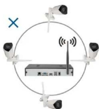
natural_image
Diagram showing four security cameras positioned around a router with signal waves, enclosed in a circle (no text or symbols)Obrázek 3-1
Obrázek 3-2
No.5, 17/F, Strand 50, 50 Bonham Strand, Sheung Wan, Hong Kong
Vyrobeno v Číně
Copyright © Abacus Electric, s.r.o.
www.evolveo.com
www.facebook.com/EvolveoCZ
natural_image
Interior view of an electronic device showing internal components and wiring (no visible text or symbols)Krok 2
natural_image
Solid dark blue rectangular object on a light surface (no text or symbols visible)Krok 3
Kroky:
2.1 Kliknite na textové pole za "Username" (Používatel'ské meno) a zadajte používatel'ské meno, predvolené systémové používatel'ské meno je "admin".
2.2 Kliknite na textové pole po "Password" (Heslo) a zadajte svoje heslo. Predvolené systémové heslo je "888888".
natural_image
Interior view of a modern office with multiple workstations and computer monitors (no visible text or signage)Obrázok 1-1
Obrázok 1-2
6. Riadenie pomocou PC
Obrázok 3-2
Obrázok 3-3
7. Vzdialené pripojenie Smartlife

natural_image
Diagram showing a network device with four cameras and a wireless router, enclosed in a circle with a checkmark (no text or symbols present)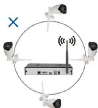
natural_image
Diagram showing four cameras positioned around a wireless router with signal waves, enclosed in a circle (no text or symbols)Obrázok 3-1
Obrázok 3-2
No.5, 17/F, Strand 50, 50 Bonham Strand, Sheung Wan, Hong Kong
Vyrobené v Číne
Copyright © Abacus Electric, s.r.o.
www.evolveo.com
www.facebook.com/EvolveoCZ
Important safety instructions and warnings: 44
Environment: 44
Main functions....44
- Hard disk installation....45
- Connection method....45
-
Basic interface control....46
-
Switching on the system....46
- Login....46
- Turn off 47
- Guide....47
- Remote device....50
- Preview....51
- Recording schedule settings....51
-
Video playback 52
-
Wireless Monitoring Kit Operating Instructions ....53
- Manual code addition method....54
- Management by PC 56
- Smartlife remote connection ....57
- Precautions for installation....60
- Security measures....61
Important safety instructions and warnings:
- Do not place heavy objects on the NVR.
- Avoid dropping solid objects on the NVR, spilling liquids on the NVR, or intrusion
- solid objects or liquids into the NVR device.
- Regularly clean the circuit boards, connectors, fans, equipment enclosure, etc. Before cleaning from
- dust, turn off the device and disconnect it from the power supply.
- Do not disassemble or repair the NVR by yourself. Do not replace parts yourself.
Environment:
- Place and use the NVR in temperatures between 0 and 40 degrees Celsius. Protect it from direct
- by sunlight. Place it at a greater distance from the heat source.
- Do not install the NVR in a humid environment.
- Do not use the NVR in a smoky or dusty environment.
- Protect it from bumping or falling.
- Ensure that the NVR is installed horizontally in a stable working environment.
- Please install it in a well-ventilated place. Keep the vents clean.
Main functions
Real-time monitoring
- Analog VGA and HDMI interface, monitor function via monitor or displays
Repository
- The hard disk does not operate during the idle interval, which contributes to less heat radiation, lower power consumption and longer life
- A special file storage format that ensures high data security
Backup
-Through SATA and USB interface to USB device, portable hard drive, etc.
-Downloading files to a hard drive over a network
Play
-Individual video recording in real time as well as search, playback, network monitoring, record check, download, etc.
-Multi-window playback mode
-Magnify any area
Network traffic
-Remote real-time network monitoring
-Remote recording control and real-time playback
Intelligent control
-Mouse action
-Quick copy and paste to ensure same setup
1. Hard disk installation
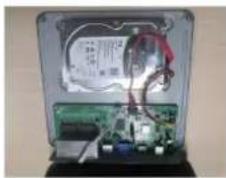
Caution: turn off the power to the device before installation. 3.5" or 2.5" HDDs up to 8TB can be used.
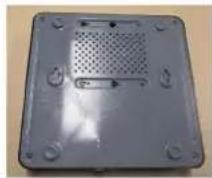
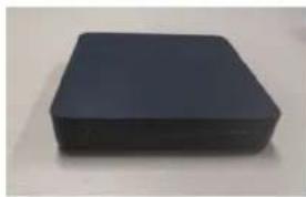
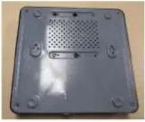
Step 1: Unscrew the screws on the cover and remove the top cover, picture below.
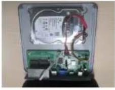
Step 2: Align the screw holes on the bottom of the HDD and the case and screw in the screws one by one. Connect the HDD cable and power cable to the motherboard, and connect the other end to the HDD.
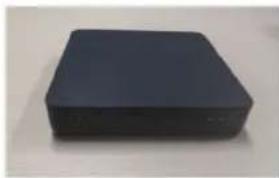
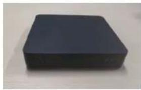
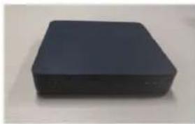
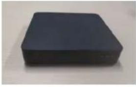
Step 3: Cover the top cover and fix it with the screws.
Step 1
natural_image
Interior view of an open hard drive showing internal circuit board and wiring (no visible text or symbols)Step 2
natural_image
Solid dark blue rectangular object on a plain background (no text or symbols visible)Step 3
Installation notes:
- Keep the instrument out of humid, high temperature and highly magnetic environments, place it in a well-ventilated area.
- Please use HDDs purchased from verified suppliers.
- Ensure that the device is properly grounded and that the power supply does not exceed the operating voltage range, we recommend using the supplied power supply.
- Do not shut down the device directly when it is running, first shut it down through the software system and disconnect it to avoid damaging the hard disk.
2. Connection method
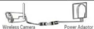
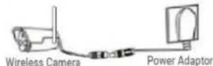
- No wiring or lengthy operations are required and the image is displayed when the device is switched on;
- There is no need to add a router, a network video recorder (NVR) with a hard drive and a built-in wireless module;
- The network camera connects wirelessly to the network hard disk recorder (NVR) via wireless automatic point-to-point code matching.
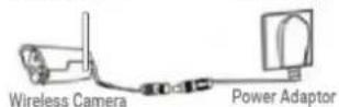
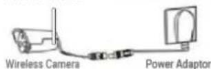
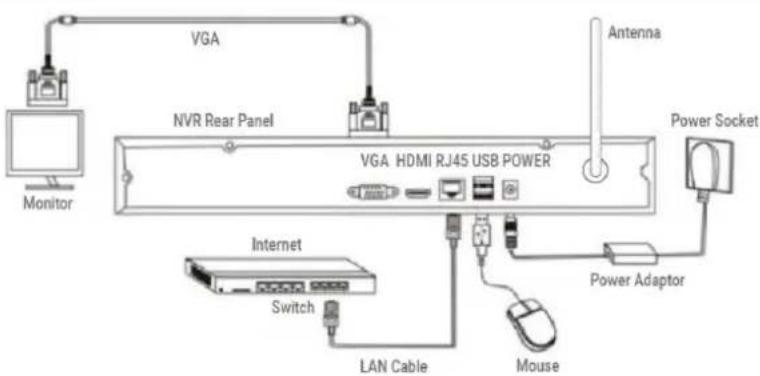
flowchart
graph TD
    A["Monitor"] --> B["VGA"]
    B --> C["NVR Rear Panel"]
    C --> D["VGA HDMI RJ45 USB POWER"]
    D --> E["Power Socket"]
    D --> F["Switch"]
    D --> G["LAN Cable"]
    D --> H["Mouse"]
    D --> I["Power Adaptor"]
    D --> J["Antenna"]
Schematic diagram
Reminder: With this wireless kit, the camera and VCR are paired wirelessly with the camera by default. Just turn on the power to the cameras and VCR to create the transmission. No operator or knowledge of network security and installation is required. A device that everyone can use!
3. Basic interface control
1. Switching on the system
When the system is turned on, the "Set User Password" interface will automatically appear as shown below:
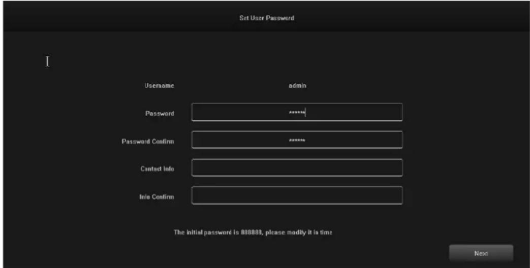
1.1 Click on the text box after "Password" and enter the password you want to change. The default system password is "888888".
1.2 Click on the text box after "Password Confirm" and enter the password again to verify it is correct. The default system password is "888888".
1.3 Click on the text box after "Contact Info" and enter your contact details to ensure that you can retrieve your password by contacting them if you forget your password. (Format example: 420-13xxxxxxxxxxx in the Czech Republic, 1-202xxxxxxxxxx in the United States) or by e-mail (e.g. sevis@evolveo.com).
1.4 Click on the text box after "Info Confirm" and re-enter your contact details to ensure that the information you have entered is correct.
1.5 Click the "Next" button to finish setting the user password.
1.6 Password changes can be skipped depending on the trustworthiness of the users.
2. Login
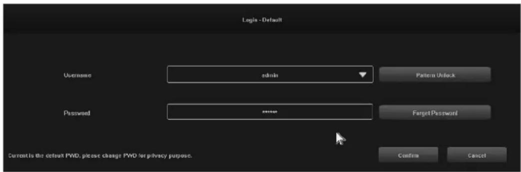
When the system is powered on, the "Login - DefaultL" interface is automatically displayed, as shown in the following image:
Steps:
2.1 Click on the text box after "Username" and enter a username, the default system username is "admin".
2.2 Click on the text box after "Password" and enter your password. The default system password is "888888".
2.3 Click on the "Confirm" button to complete the login.
2.4 Click on "Pattern Unlock" and log in using the pattern you have set.
2.5 Click on the "Forget Password" button to retrieve your password via the contact details you have entered.
3. Turn off
Illustration of function: shutdown and restart can be controlled.
Steps:
3.1 Click the "Shut down" button in the main menu, then the interface below will be displayed:
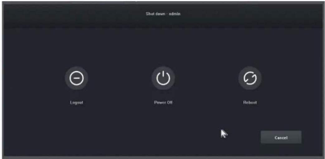
3.2 Click on the "Power Off" button and turn off the system.
4. Guide
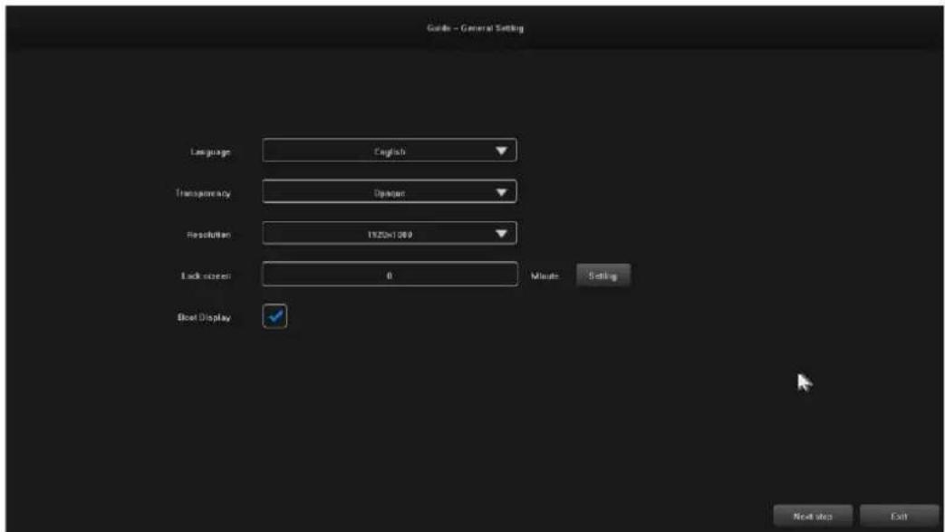
After logging in, the "Guide-General Setting" interface opens by default, which guides the user through the basic settings to allow the machine to operate normally.
Steps:
4.1 Settings 1: The user can set the language/transparency/resolution and other menu options, see the following image:
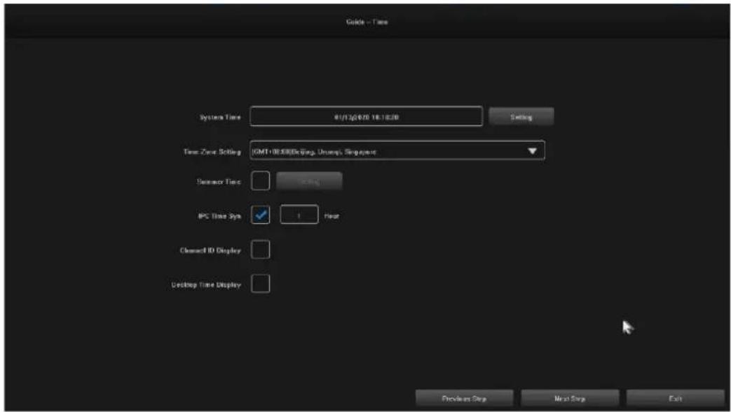
4.2 Settings 2: System Time / Time Zone Settings / Daylight Saving Time and other menu options can be set by users, see image below:
4.3 Settings 3: The network connection can be set up by users, see image below:
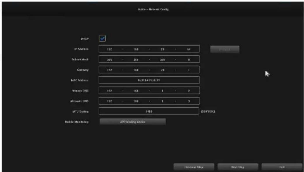
4.4 Settings 4: Users set up recording schedules according to their needs, see image below :
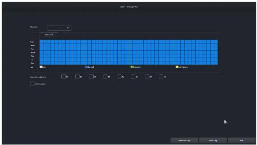
4.5 Settings 5:Users can set the format and recording schedule of HDD, see the figure below:
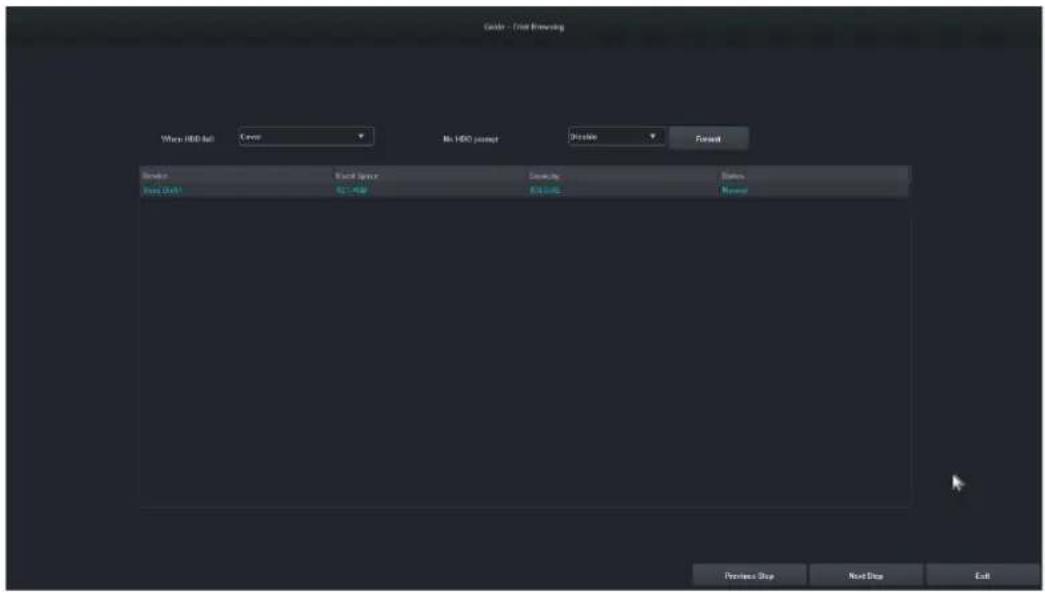
4.6 Settings 6: Information about all IPC devices of this NVR will be displayed, and click "Finish" to complete the configuration of the startup wizard.
5. Remote device
The wizard is completed or click on "Remote Device" to enter, the image is as follows:
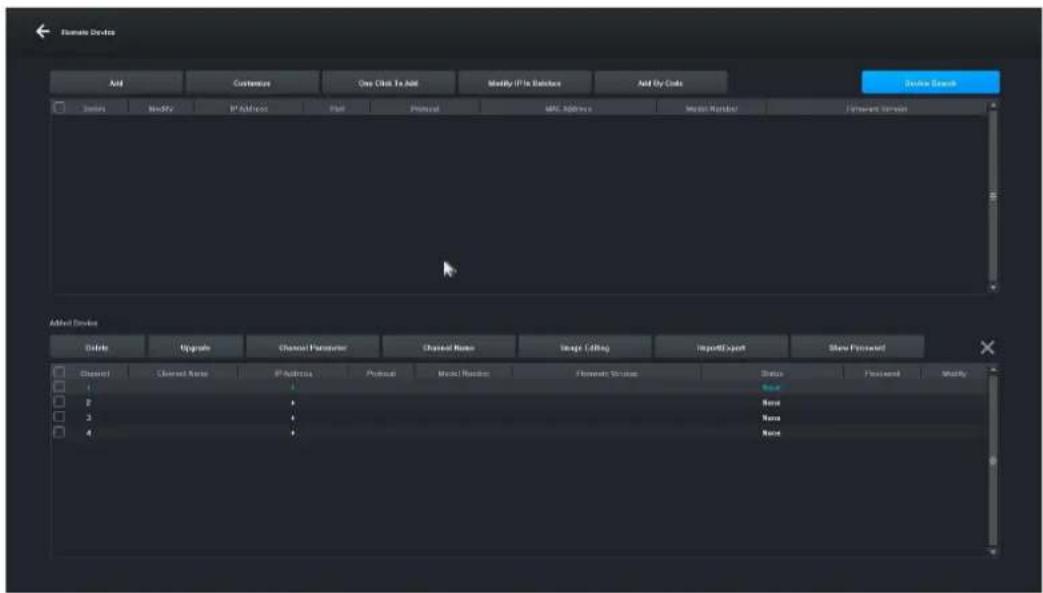
[Device Search] Click "Device Search" to search for a device.
[Add] Check the devices you are looking for and click the "Add" button to add the device.
[Customize] " Manually add" devices based on the IP address of the device.
[One-click add] Add all searched devices.
[Bulk IP Edit] Search for a device and edit the IP address of the device in the group.
[Remove] After you have successfully added a device, you can remove it.
[Upgrade] After successfully adding the device, you can upgrade the firmware after checking.
[Channel parameter] After successfully adding a device, you can edit the channel information of the device.
[Channel Name] The channel name can be changed after the device is successfully added.
[Image editing] After successfully adding the device, you can enter the image editing interface.
[Import\Export] After successfully adding the device, you can import/export the device channel configuration information.
[Show Password] Enter the administrator password, the camera user password will be displayed.
[Previous step] Return to the previous interface.
[Completed] The boot wizard is complete, go to the preview interface.
6. Preview
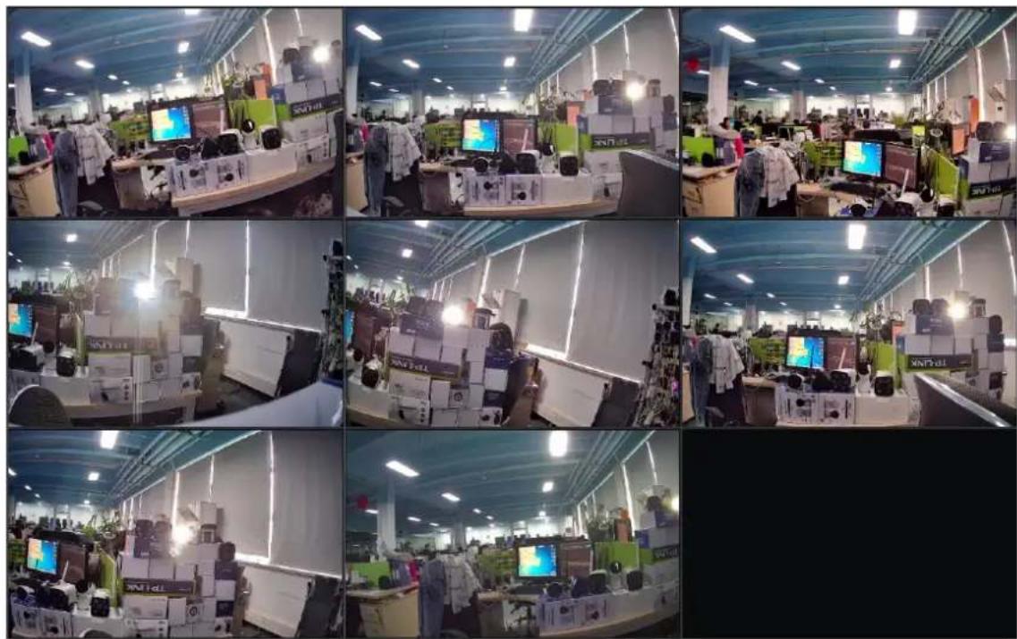
After a successful login, the device will go to the preview screen. Each preview screen shows the date/time/channel name, and at the bottom of the screen there is a line indicating the recording and alarm status of each channel, see figure below : .
natural_image
Interior view of a modern electronics lab with multiple workstations and computer monitors (no visible text or symbols)7. Recording schedule settings
Feature illustration: Used to set the recording schedule. By default, the system will allow all-day recording.
Steps:
7.1 Click "Main Menu" -> "Storage Settings", the interface for recording settings will open, the picture is shown below:
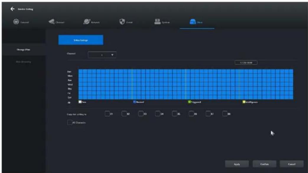
7.2 Click and select "Free [1]", "Normal [2]", "Triggered [3]", "Intelligence [4]" and set the recording schedule for the current channel, the minimum range is 30 minutes.
7.3 After selecting the record type, simply drag the mouse to complete the settings for removing or adding the record plan. You can also click the button on the left to quickly set it up.
7.4 Once the current channel has been set, you can select the channel to be copied by selecting "Copy this setting to other channels" and clicking the "Apply" button to save it.
8. Video playback
Feature illustration: It is used to query and play a recording of any channel.
Steps:
8.1 Click on the "Recording Inquiry" menu or "Main menu" -> "Recording Inquiry", the video playback interface will open, the picture is shown below:
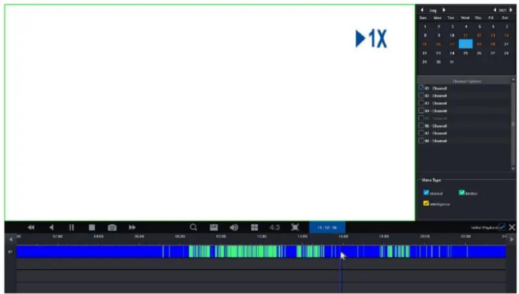
8.2 Click on the date in the calendar. A date highlighted in blue means that a record was made on that day. A date highlighted in white means that there is no record on that date.
8.3 Click to select the channel number of the video to be played. Depending on the difference in models, a preview of the selected channel's playback interface will be displayed by default.
8.4 Click to select the record type. Record types: "Normal", "Motion" and "Intelligence" for filtering. Normal is marked in blue, motion in green, smart in yellow.
8.5 Click the "Play" button to play the video files that meet the conditions; you can also double-click on the video slider for quick playback.
4. Wireless Monitoring Kit Operating Instructions
- Check that the power supply to the network video recorder with hard disk and cameras is OK.
- If you need to manage the device remotely, you will need to connect it via a network cable to your local network that has Internet access.
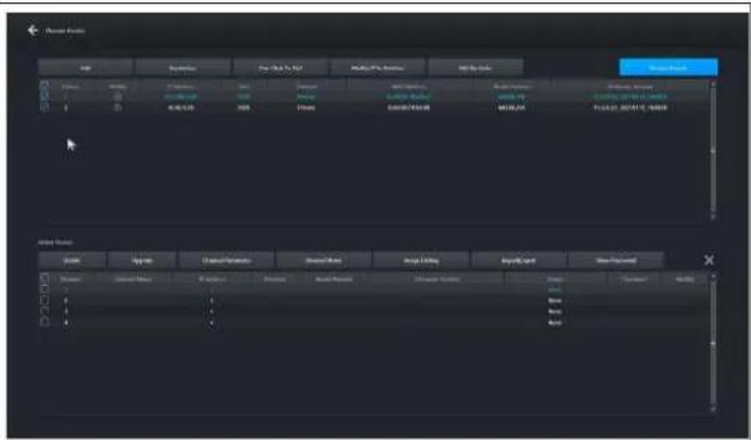
- In the main interface of the network hard disk video recorder, right-click to enter the main menu and click "Remote Device -> Device Search -> Search Camera" as shown in Figure 1-1.
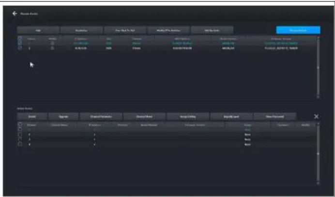
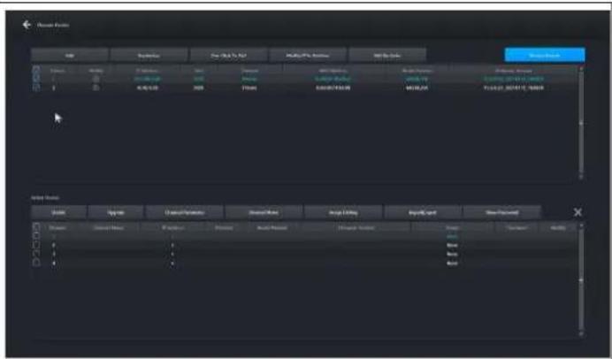
- Select all cameras and click the "Add" button as shown in Figure 1-2.
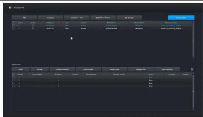
Figure 1-1
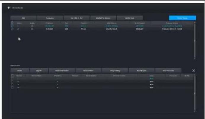
Figure 1-2
- View the list of added devices. The status of the device will be displayed as "Connected", indicating that the camera has been successfully added, as shown in Figure 1-3.
- Right-click to return to the preview page and display the monitor screen.
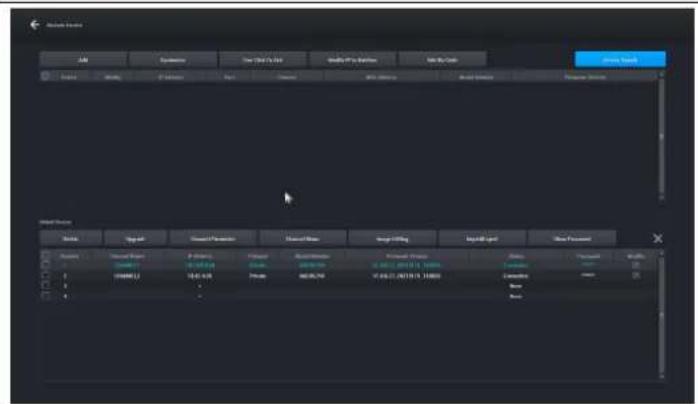
Figure 1-3
5. Manual code addition method
The wireless monitoring kit, network camera, and network video recorder with hard drive have been paired wirelessly by default. You only need to power the camera and the VCR to output the image, without the need to pair individual cameras. (If you need to check the code manually, the procedure is as follows.)
Method 1: Connecting the device (assigning a wireless code):
- Turn on the network camera and the network video recorder with the hard disk and connect the network camera and the network video recorder with the hard disk using the network cable.
- Then enter the "Remote Device" interface of the network video recorder with hard disk and click the "Add By Code" button as shown in the figure below:
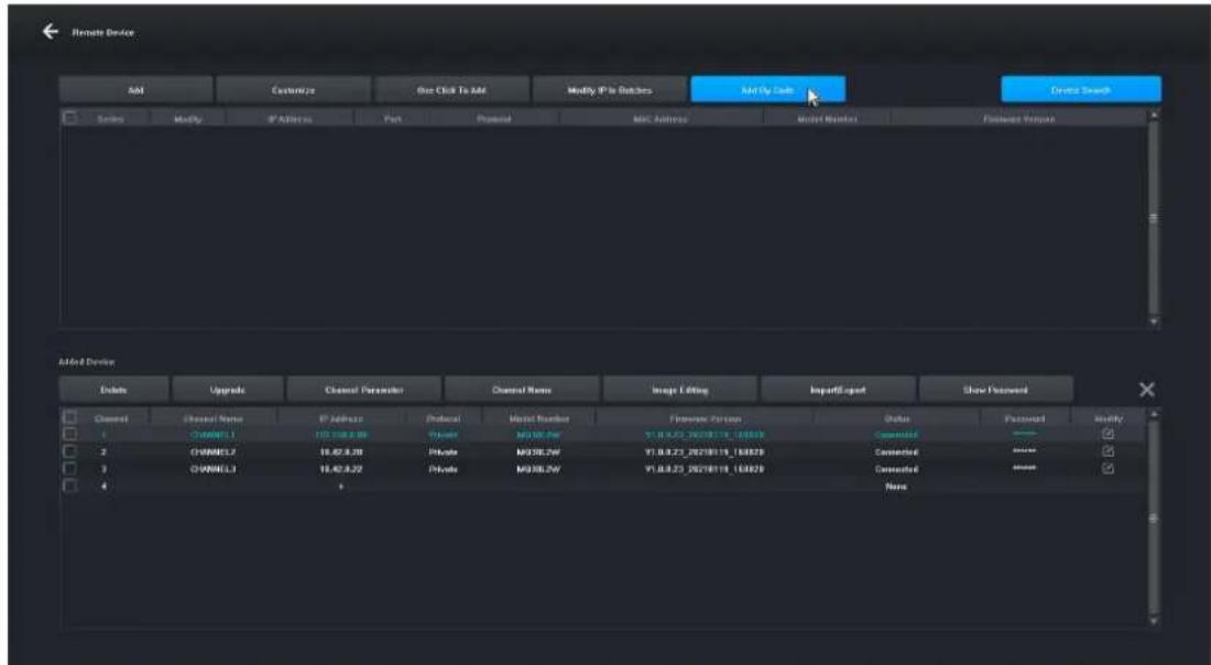
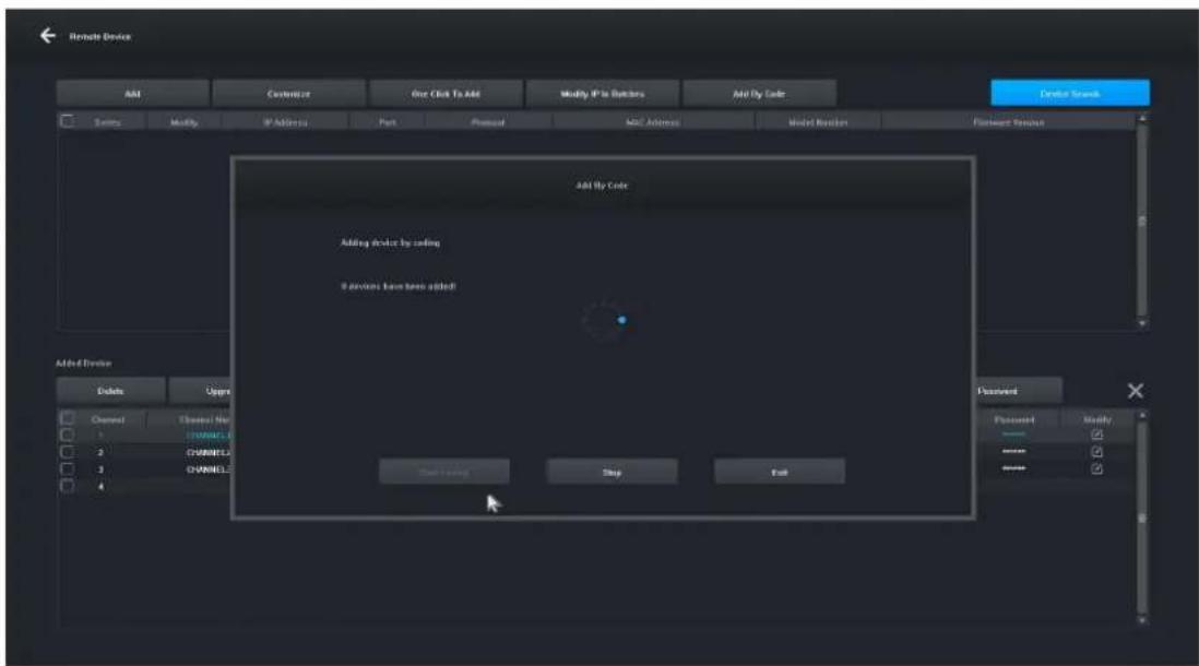
- Enter the "Add By Code" interface, click the "Start Coding" button, the network video recorder with hard disk will automatically pair the code with the network camera, and the system will perform code pairing for 20 seconds. When the interface prompts that a device has been added! , it means that the code has been successfully assigned, as shown in the figure below:
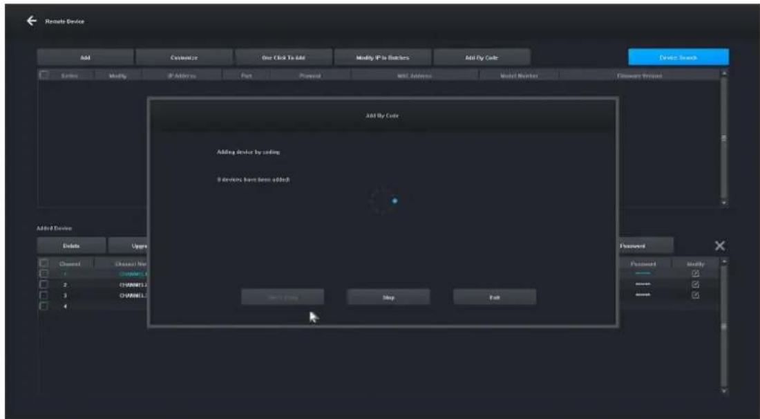
Method 2: Network connection (wireless code matching):
- Turn on the network camera and network video recorder with hard disk and connect the network camera and network video recorder with hard disk to the same network.
- Then enter the "Remote Device" interface of the network video recorder with hard disk and click the "Add By Code" button as shown in the figure below:
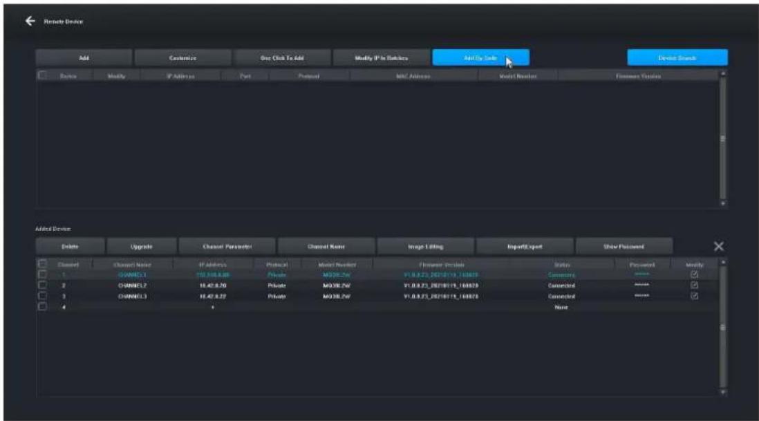
- Enter the "Add By Code" interface, click the "Start Coding" button, the network video recorder with hard disk will automatically pair the code with the network camera, and the system will perform code pairing for 20 seconds. When the interface prompts that one device has been added!, it means that the code has been successfully assigned, as shown in the figure below.
6. Management by PC
- Install the iCMS client on your computer download at www.evolveo.com
- Log in to the system
2.1 Login client, username: admin, password: admin. The interface as shown in Figure 3-1 is displayed
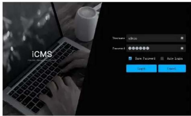
Figure 3-1
2.2 Check that the network video recorder with hard disk is properly connected to the network. (Connect the power cord and power supply)
2.3 Set the IP address, subnet mask and gateway for the host computer and the network video recorder with hard disk (if there is no router on the network, assign the IP address of the same network segment. If there is a router on the network, you need to set the appropriate gateway and subnet. Netmask), the network settings of the network hard disk VCR can be found in [Main Menu] > [Network Settings].
2.4 Use the CMD command line command "ping ***.***.***." (IP address of the network VCR with hard disk) to check if the network is connected.
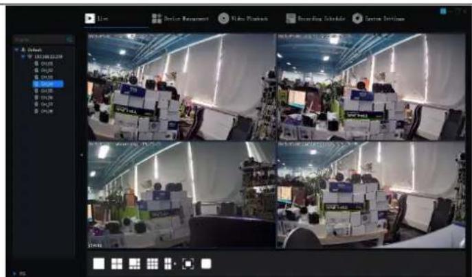
2.5 Open the client, click "Device Management" -> "Search" and click the Add button as shown in Figure 3-2.
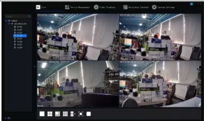
2.6 After successfully adding, select "Video Preview", click the preview of the video output device, and the interface shown in Figure 3-3 will be displayed.
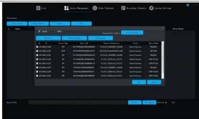
Figure 3-2
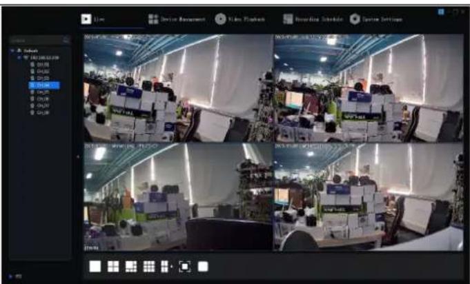
Figure 3-3
7. Smartlife remote connection
Remark: Before using the Smart Life remote connection, make sure the network video recorder is already connected to the Internet.
Step 1: Download the Smart Life app
- Android users can download the "Smart Life" app via the APP Market.
- An iOS user can download the "Smart Life" app via the APP Store.
- Android and iOS users can scan the following QR code and download the "Smart Life" app.


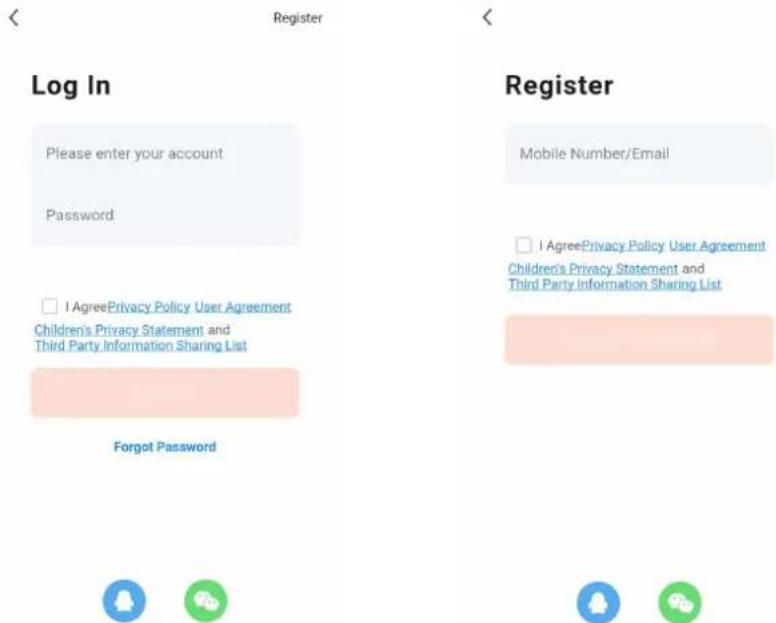
- Open the "Smart Life" app and press the "Register" button to register a new account. If you have an account, you can log in with your account and password.
Step 2: To add a network video recorder with a hard drive to Smart Life
-
Make sure that the wireless network connection of the mobile phone and the network video recorder and hard disk drive are on the same local network.
-
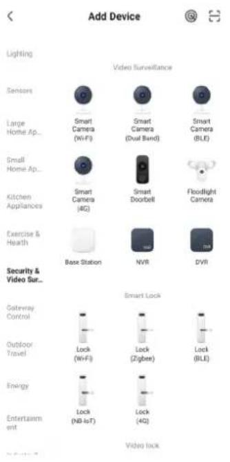
Open the "Smart Life" app and log in successfully, click the [Add Device] button or click the [+] button to add a device as shown below:
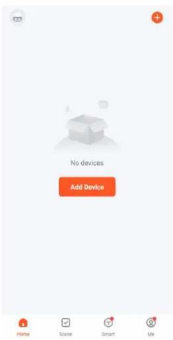
- Access the [Manual Add] page, select [Video Surveillance], and click the NVR icon as shown below:
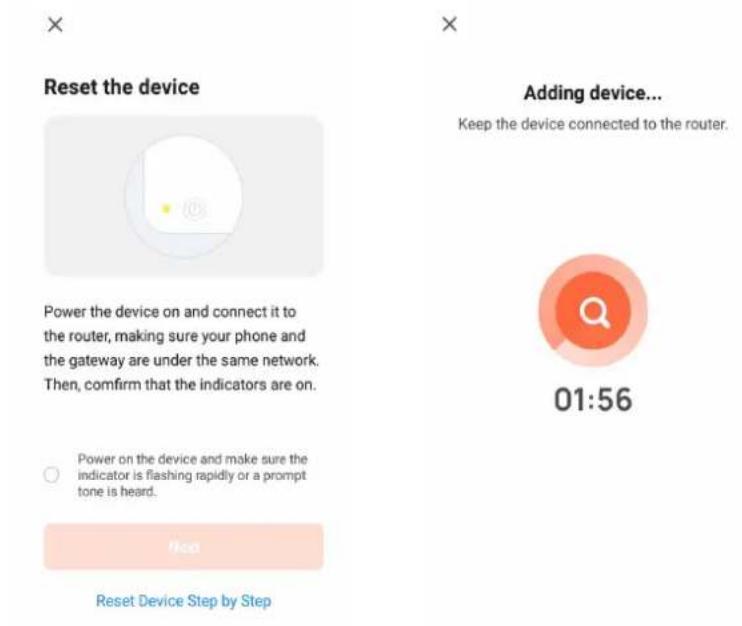
- Follow the instructions on the page to verify that the power to the network video recorder with hard drive and the network light are steady and blue, and then click the "Next" button to enter the connected device page as shown below:
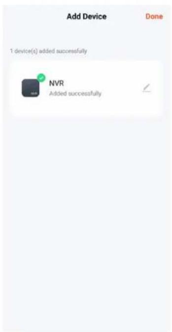
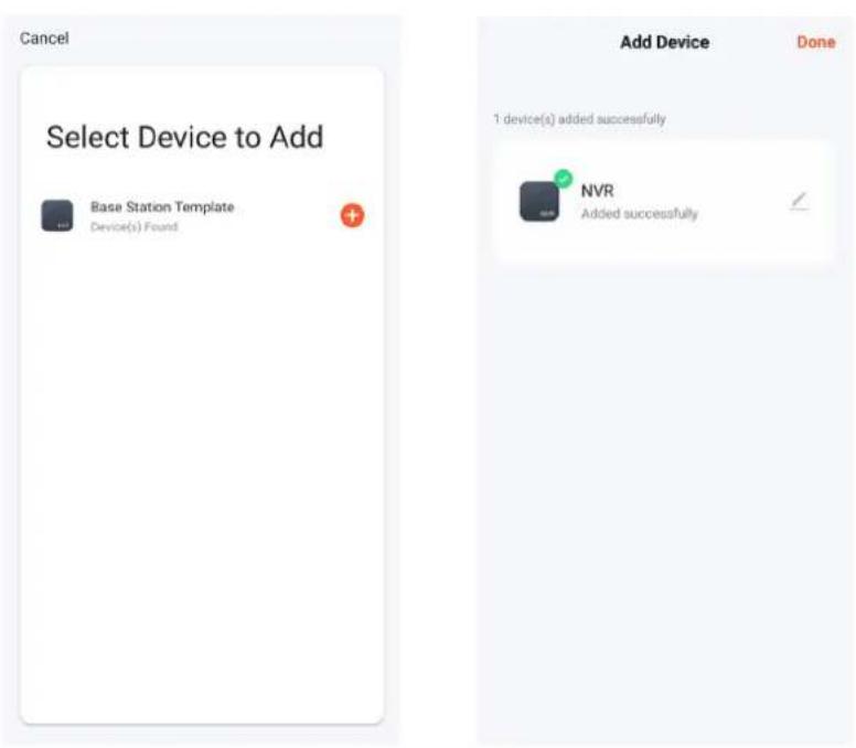
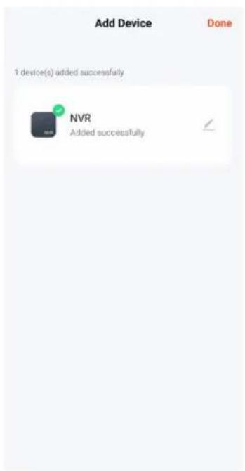
- After successfully connecting the device, select the "Add Device" option, click the [+] button to enter the connection page, and after being prompted that the addition was successful, click the "Finish" button to successfully add the device as shown in the figure below:
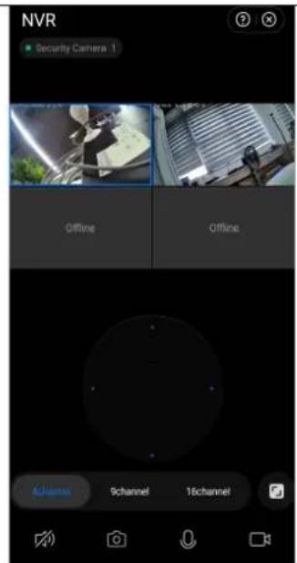
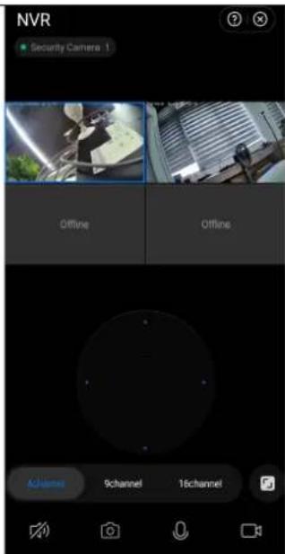
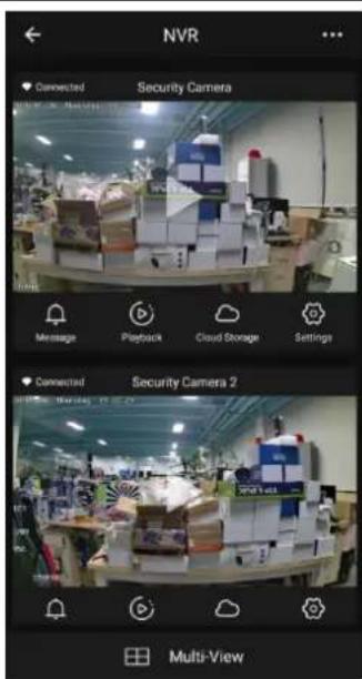
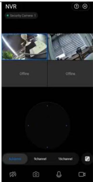
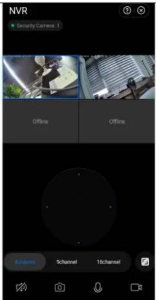
- To preview the image, click the corresponding smart camera, enter the real-time image preview page, and click the [Multi-channel Preview] button to perform simultaneous multi-channel preview as shown below:
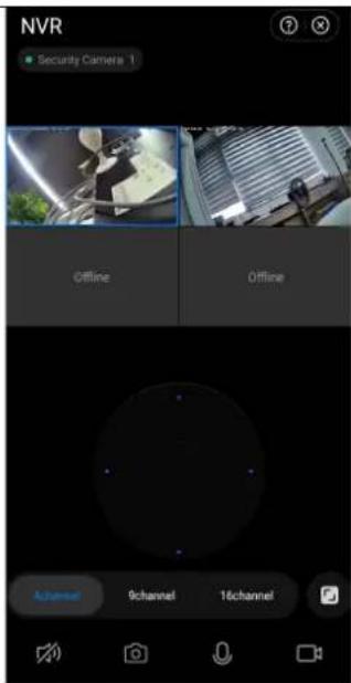
8. Precautions for installation
- The wireless monitoring device uses wireless automatic calibration technology. Only after the power supply is complete can the camera be located and added to the NVR. There is no need to enter the code manually.
- Check the preset position of the wireless NVR before installation. We recommend placing the wireless NVR in the center of the monitored area. Avoid obstacles between the camera and the NVR.
- Check that the camera is connected to the wireless NVR kit and that the image can be previewed. Then install the camera in a pre-selected location within effective wireless coverage.
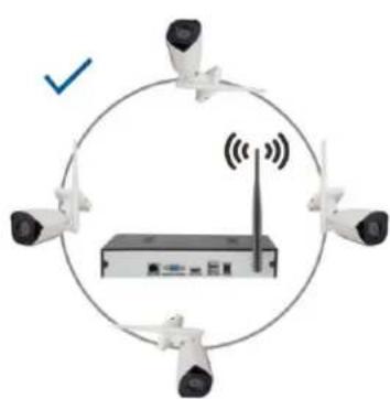
- Because the NVR wireless antenna transmits the signal to the peripheral device, the NVR antenna and the camera antenna should be at the same height and parallel to each other, as shown in Figure 3-1. Figure 3-2 shows an incorrect installation.
natural_image
Diagram showing four cameras positioned around a network device with wireless signal, enclosed in a circle (no text or symbols)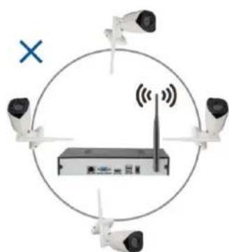
natural_image
Diagram showing four security cameras positioned around a network device with a radio, enclosed in a circle (no text or symbols present)Figure 3-1
Figure 3-2
9. Security measures
- Do not place any containers (e.g. vases) with liquid on the VCR.
- The network video recorder should be placed in a sufficiently ventilated area to avoid blocking the air vents.
- Check the power supply and voltage to prevent damage due to voltage mismatch.
- The network video recorder should operate within the temperature and humidity range allowed by the technical specifications.
- The network video recorder should be placed horizontally and avoid installation in an environment with high vibration.
- Dust on the circuit board can cause a short circuit when it gets wet. In order to keep the NVR working normally for a long time, you can periodically use a brush to remove the dust on the circuit board/interconnect panel/enclosure etc.
- Improper battery replacement can cause an explosion. It is not recommended to replace the battery yourself. If you need to replace it, only replace it with the same or equivalent type battery, do not attempt to open or repair the battery.
- the installation and location of the network video recorder shall be in accordance with the specifications, which may refer to relevant national or local standards.
FAQ
Q: Is the camera waterproof
A: Equipped with IP 66 protection, the camera will function when exposed to weather conditions such as rain and snow. However, for proper operation it is necessary that the power connector and the mains connector are covered, otherwise the camera loses its degree of protection and the claim cannot be accepted.
Q: Camera cannot be added
A: check the correct IP address range of the camera and recording device, make sure you have entered the correct camera login details
Q: Remote monitoring via mobile app does not work
A: Check the network connection of the NVR and the availability of the Internet connection. Make sure your PC is in the same IP range as the NVR.
The warranty does NOT cover:
- using the equipment for purposes other than those for which it is designed,
- installing firmware other than that installed on the device
- electrical or mechanical damage caused by improper use
- damage caused by natural elements such as water, fire, static electricity, power surges, etc.
- damage caused by repairs carried out by an unqualified person
- illegible serial number
- battery capacity drops after 6 months of use (6 month battery life guarantee)

Disposal
The crossed-out container symbol on the product, in the accompanying documentation or on the packaging reminds you that in EU countries, all electrical and electronic equipment, batteries and accumulators must be disposed of separately at the end of their useful life as part of sorted waste. Do not dispose of these products in unsorted municipal waste.


DECLARATION OF CONFORMITY
Abacus Electric, s.r.o. hereby declares that the product EVOLVEO Detective WN8 SMART meets the requirements of the standards and regulations that are relevant for the type of equipment.
The full text of the Declaration of Conformity can be found at ftp://ftp.evolveo.com/ce
Importer / Importer / Importer / Importer
Abacus Electric, s.r.o.
Planá 2, 370 01, Czech Republic
Producer / Producer / Manufacturer / Gyártó
Naxya Limited
No.5, 17/F, Strand 50, 50 Bonham Strand, Sheung Wan, Hong Kong
Made in China
Copyright © Abacus Electric, s.r.o.
www.evolveo.com
www.facebook.com/EvolveoCZ
All rights reserved.
The appearance and technical specifications of the product are subject to change without notice.
Tartalom
natural_image
Interior view of an open electronic device showing internal components and wiring (no visible text or symbols)- lépés
natural_image
Solid dark blue rectangular object with no visible text or symbols- lépés
Lépések:
natural_image
Interior view of a modern office with multiple workstations and computer monitors (no visible text or signage)1-1. ábra
1-2. ábra
3-3. ábra

Power the device on and connect it to the router, making sure your phone and the gateway are under the same network. Then, confirm that the indicators are on.
Power on the device and make sure the indicator is flashing rapidly or a prompt tone is heard.
Keep the device connected to the router.
natural_image
Diagram showing four cameras positioned around a wireless router with signal waves, enclosed in a circle (no text or symbols)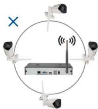
natural_image
Diagram showing four cameras positioned around a network device with signal waves, enclosed in a circle (no text or symbols)3-1. ábra
3-2. ábra
No.5, 17/F, Strand 50, 50 Bonham Strand, Sheung Wan, Hong Kong
Made in China
Copyright © Abacus Electric, s.r.o.
www.evolveo.com
www.facebook.com/EvolveoCZ
Minden jog fenntartva.
 |  |  |
| Pasul 1 | Pasul 2 | Pasul 3 |
Note de instalare:
Paşi:
natural_image
Interior view of a modern office with multiple workstations and employees at computer stations (no visible text or signage)6. Management prin PC
Figura 3-2
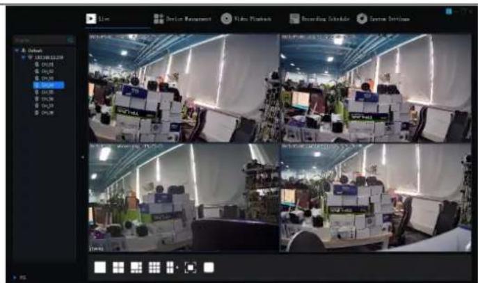
Figura 3-3

natural_image
Diagram showing four cameras positioned around a wireless router with signal waves, enclosed in a circle (no text or symbols)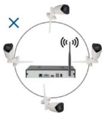
natural_image
Diagram showing four surveillance cameras positioned around a network device with a central tower, enclosed in a circle with a blue 'X' symbol (no text or labels present)Figura 3-1
Figura 3-2
9. Măsuri de securitate
No.5, 17/F, Strand 50, 50 Bonham Strand, Sheung Wan, Hong Kong
Fabricat în China
Copyright © Abacus Electric, s.r.o.
www.evolveo.com
www.facebook.com/EvolveoCZ
| NVR Power Adaptor | ||
| Information published | Value and precision | Unit |
| Manufacturer's name or trade mark, commercial registration number and address | Dongguan Sunun Power Co., Ltd | - |
| Model identifier | SA24BH-120200V | - |
| Input voltage | 100~240Vac | V |
| Input AC frequency | 50/60Hz+/-3Hz | Hz |
| Output voltage | 11.4~12.6Vdc | V |
| Output current | 2A | A |
| Output power | 24W | W |
| Average active efficiency | 86% % | |
| Efficiency at low load (10 %) | 88% % | |
| No-load power consumption | 0.1W | W |
| Camera Power Adaptor | ||
| Information published | Value and precision | Unit |
| Manufacturer's name or trade mark, commercial registration number and address | Zhuhai Bright Source Electronic Science&Technology Co.,LTD | - |
| Model identifier | CYH012S012V1000E | - |
| Input voltage | 100~240Vac | V |
| Input AC frequency | 50/60Hz+/-3Hz | Hz |
| Output voltage | 11.4~12.6Vdc | V |
| Output current | 1A | A |
| Output power | 12W | W |
| Average active efficiency | 83% % | |
| Efficiency at low load (10 %) | 83% % | |
| No-load power consumption | 0.1W | W |


- Obsah / Content / Tartalom / Cuprins
- Obsah
- Schématický diagram
- Kroky:
- Správa pomocí PC
- Riadenie pomocou PC
- Vzdialené pripojenie Smartlife
- Important safety instructions and warnings:
- Environment:
- Main functions
- Real-time monitoring
- Repository
- Backup
- Play
- Network traffic
- Intelligent control
- Hard disk installation
- Installation notes:
- Connection method
- Schematic diagram
- Basic interface control
- Switching on the system
- Login
- Steps:
- Turn off
- Guide
- Remote device
- Preview
- Recording schedule settings
- Video playback
- Wireless Monitoring Kit Operating Instructions
- Manual code addition method
- Method 2: Network connection (wireless code matching):
- Management by PC
- Smartlife remote connection
- Precautions for installation
- Security measures
- FAQ
- The warranty does NOT cover:
- Disposal
- DECLARATION OF CONFORMITY
- Tartalom
- Lépések:
- Note de instalare:
- Paşi:
- Management prin PC
- Măsuri de securitate
Brand : Evolveo
Model : Detective WN8 SMART
Category : Home Automation