MCD 30 - Bluetooth speaker GRUNDIG - Free user manual and instructions
Find the device manual for free MCD 30 GRUNDIG in PDF.
User questions about MCD 30 GRUNDIG
0 question about this device. Answer the ones you know or ask your own.
Ask a new question about this device
Download the instructions for your Bluetooth speaker in PDF format for free! Find your manual MCD 30 - GRUNDIG and take your electronic device back in hand. On this page are published all the documents necessary for the use of your device. MCD 30 by GRUNDIG.
USER MANUAL MCD 30 GRUNDIG
Hints for correct and safe operation 2
How to use the magazine 3
Loading a disc 3
Installing the magazine 3
Precautions for handling discs 4
With 8 cm CDs 4
Storing the 8 cm CD adapters 4
With new discs 4
Installation parts 5
ID (Identity) switch for CD changer 5
Before installing the unit 6
Transport lock screws 6
Installation and wiring precautions 6
Position of the built-in anti-vibration board 7
Wiring 7
Installation 8
Procedure for installation on carpet (horizontal position) 8
Procedure for installation on carpet (vertical position) 9
Procedure for installation on carpet (at a 45^ angle) 10
Procedure for installation (suspended position) 11
Handling the discs 12
Troubleshooting 13
Hints for correct and safe operation
This CD Changer is designed to be operated only on +12 volt DC negative ground systems. The unit cannot be used on +24 volt or positive ground systems.
At very high or very low temperatures it may happen that the radio does not function properly. An overload protection circuit responds if the temperature reaches a specified limit value. The unit then switches automatically off. In this case, open the car window or switch on the heating (air-conditioning) and wait until the temperature meets again the admissible operating conditions.
Condensation
Moisture can condense on the laser lens of the CD changer during rainy and humid days, or right after the heater is turned on in the car. If this should happen the unit will not operate correctly. To remedy the situation, remove the magazine from the unit and wait approximately one hour. During this time the moisture will evaporate and the unit will operate normally.
Remove the magazine from the unit when it is not being used during hot weather and the CD changer is not used for long periods of time.
When using 8 cm CDs, use a 8 cm CD adapter which conforms to CD standards and be sure to load the CDs in trays No. 1, 3, and 5 (gray trays). Loading CDs into other trays will result in a malfunction.
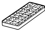
How to use the magazine
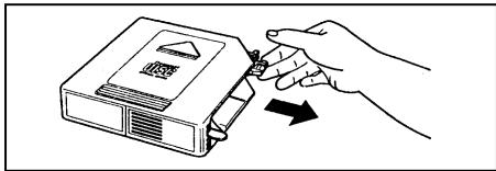
Loading a disc
Pick the tab on the magazine's disc tray and pull out only one of the trays.
Place the disc on the tray with its play surface facing up (label surface facing down).
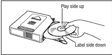
- Each tray can accommodate only one disc.
-E-07" appears about 8 seconds if the disc is placed upside down.
Press the tab on the disc tray to store the tray back in the magazine.
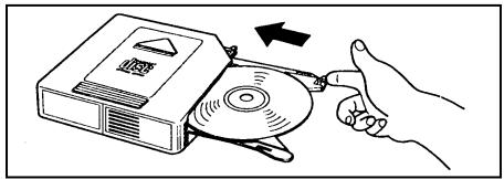
- Up to six discs can be loaded.
- Use the 8 cm CD adapter for 8 cm discs. (See page 4).
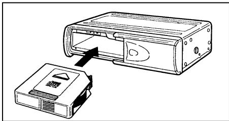
Installing the magazine
Slide the door toward the right.
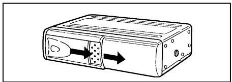
First check that the magazine with the discs inside has its top side facing up and that it is pointed in the right direction for installation. Push it in until it clicks into place, indicating that it is now locked.
- When the magazine is used for the first time, it will not lock into place unless the power supply has been connected.
Ejecting the magazine
The magazine is ejected by pressing the eject button () .
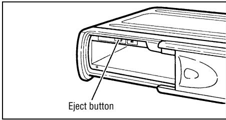
Notes:
Be absolutely sure to close the door after having inserted or ejected the magazine. Dust or dirt finding its way inside may cause malfunctioning of the unit.
Precautions for handling discs
With 8 cm CDs
When using 8 cm CDs, use a 8 cm CD adapter which conforms to CD standards and be sure to load the CDs in trays No. 1, 3, and 5 (gray trays). Loading CDs into other trays will result in a malfunction.
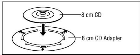
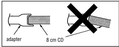
Be sure to attach the disc properly to the catches provided on the adapter.
If the disc is not attached correctly, it may come free inside the magazine or play mechanism, rendering the unit inoperable.
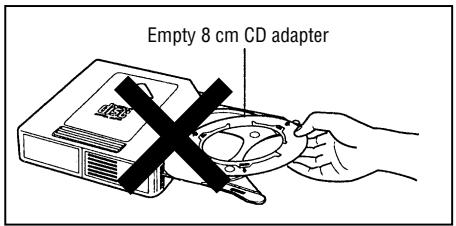
Storing the 8 cm CD adapters
Under no circumstances must an empty 8 cm CD adapter be loaded inside the magazine.
If this warning is not heeded, the adapter will remain inside the mechanism, rendering the unit inoperable.
WARNING
Although protective film is being marketed as CD accessories, use of these products will result in malfunctions and should absolutely be avoided.
With new discs
The symptoms described below sometimes occur when new discs are used.
- The disc is not played even when it is loaded.
Operation changes to the next disc before the first disc has a chance to be played. - The same disc is played over and over again.
- The designated disc is not played.
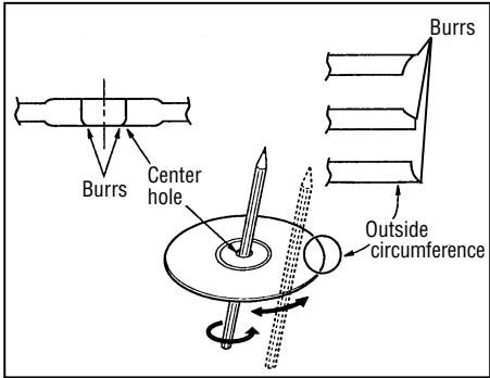
These symptoms occur when there are burrs on the center hole or outside circumference of the disc and, as a result, the disc has not been loaded properly or the disc catches on something inside the magazine.
In cases like these, remove the burrs using a ball-point pen or similar implement, as shown in the figure below.
Installing parts
ID (Identity) switch
Bracket (L)
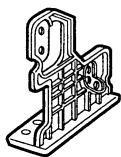
X1
Bracket (R)
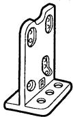
X1
Bracket (B)
X2
Hexagonal bolt (M6 x 20)
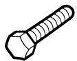
X4
Hexagonal bolt with washer
(M5 x 8)

X4
Nut (M6)

X4
Tapping screw (M5 x 12)

X4
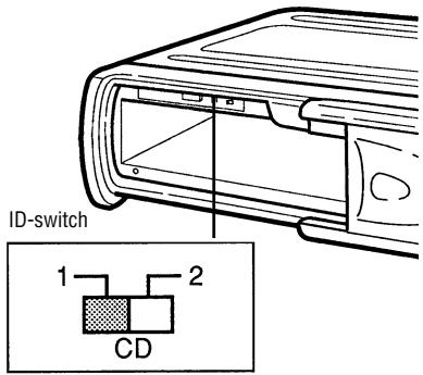
The ID switch must be set to position "1".
Before installing the unit
Transport lock screws
The mechanism in the CD changer is "locked" into place during shipment by the transport screws.
Be sure to remove the screws prior to installation.
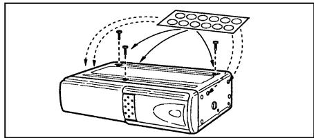
Caution:
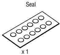
After removing the transport lock screws, place the supplied seals over the screw holes. These seals are used to keep dust, which could cause a malfunction, out of the unit.
Installation and wiring precautions
To prevent a short-circuit:
- Be sure to turn off the ignition and remove the negative (-) battery cable prior to installation.
Note:
If the changer is to be installed in a car that is equipped with an on-board drive or navigation computer, do not disconnect the battery cable. If the cable is disconnected, the computer memory may be lost. Under these conditions, use extra caution to avoid causing a short circuit during installation.
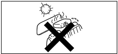
Do not install the unit in the following locations:
- Locations exposed to direct sunlight.
- Where hot air is discharged from the car heater.
- When proper installation is not possible and where a great deal of vibration is generated.
- Be sure to use the supplied brackets and screws.
- When installing the unit, do not use any screws that are part of the brake or steering system.
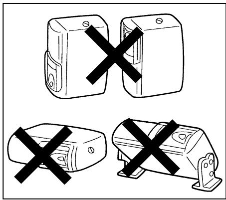
This unit cannot be installed in any way except that which is authorized (on its side, on its end, at a 45^ angle or suspended). Installing it with its side facing down or upside down can cause malfunctioning.
Before installing the unit
Wiring
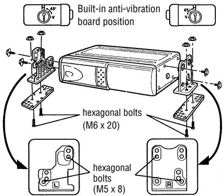
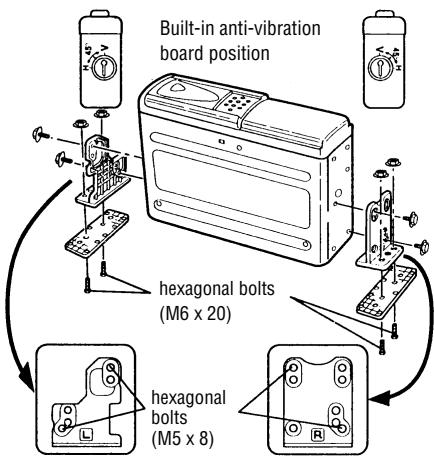
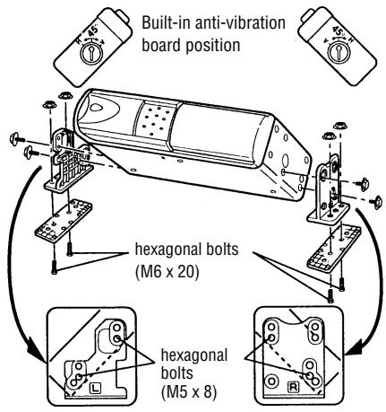
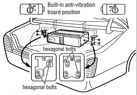
Position of the built-in anti-vibration board
This unit can be installed horizontally (suspended), vertically, and at a 45^ angle. Once the installation position has been decided, it's necessary to set the position of the built-in anti-vibration board inside the unit. Please do this before performing the procedure listed below. Vibration may cause the disc to skip if the unit is used before properly setting the anti-vibration board.
- At the time of shipping, the built-in antivibration board is set for horizontal installation "H".
- The are built-in anti-vibration boards on both the left and right sides.
- Set the anti-vibration board position with a screwdriver before attaching the brackets.
For use when unit is installed horizontally or suspended:
Confirm that the built-in anti-vibration board is set to position "H".
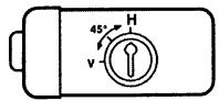
For use when unit is installed vertically:
The built-in anti-vibration board should be set to position "V".
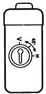
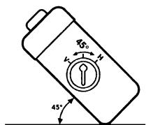
For use when unit is installed at a 45^ angle:
The built-in anti-vibration board should be set to position "45".
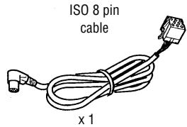
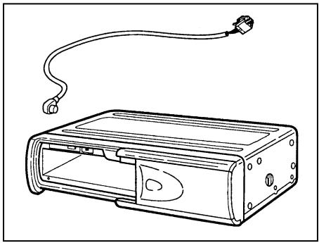
Connect the CD changer with the cable supplied to a car radio equipped accordingly (see operating instructions):
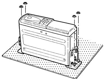
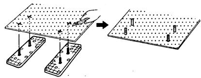
Procedure for installation on carpet (horizontal position)
1 - Confirm that the built-in anti-vibration boards on both the left and right sides are set to the horizontal installation position "H".
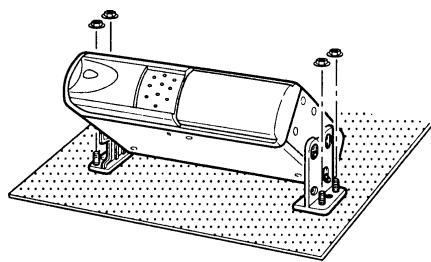
- Attach bracket (L) and bracket (R) using the hexagonal bolts (M5× 8) .
- Attach brackets (L) and (R) to their respective brackets (B) using the hexagonal bolts (M6 x 20) and the hexagonal nuts (M6).
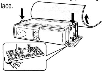
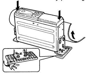
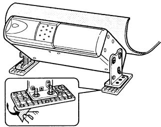
2 - Pull back the carpet and determine where to attach the unit.
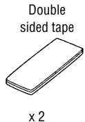
- Stick the supplied double-sided tape to the bottom of the brackets (B) and peel off the paper backing.
- Affix the unit to the floor by pressing in place.
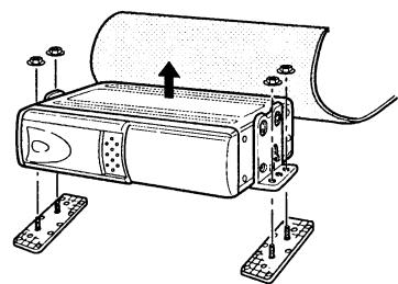
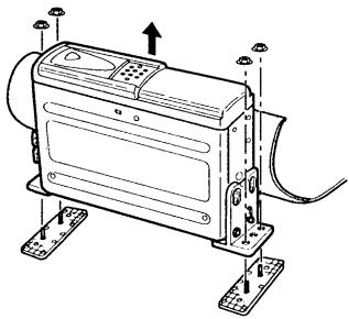
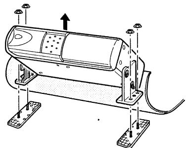
3 - Remove the hexagonal nuts and take off the changer.
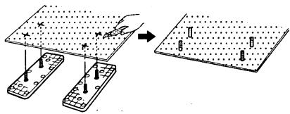
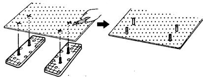
4 - Using a knife, cut "X"s in the carpet directly above the brackets (B) bolts.
- Return the carpet to its original position allowing the bolts to stick through.
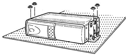
5 - Once more, use the hexagonal nuts to attach the changer on top of the carpet.
Procedure for installation on carpet (vertical position)
1 - Set that the built-in anti-vibration boards on both the left and the right sides are set to the vertical installation position "V".
- Attach brackets (L) and (R) using the hexagonal bolts (M5 × 8) .
- Attach brackets (L) and (R) to their respective brackets (B) using the hexagonal bolts (M6 x 20) and the hexagonal nuts (M6).
2 - Pull back the carpet and determine where to attach the unit.
- Stick the supplied double-sided tape to the bottom of the brackets (B) and peel off the paper backing.
- Affix the unit to the floor by pressing in place.
3 - Remove the hexagonal nuts and take off the changer.
4 - Using a knife, cut "X"s in the carpet directly above the brackets (B) bolts.
- Return the carpet to its original position allowing the bolts to stick through.
5 - Once more, use the hexagonal nuts to attach the changer on top of the carpet.
Procedure for installation on carpet (at a 45^ angle)
1 - Set the built-in anti-vibration boards on both the left and the right sides to the 45^ installation position "45".
- Attach brackets (L) and (R) using the hexagonal bolts (M5 × 8) .
- Attach brackets (L) and (R) to their respective brackets (B) using the hexagonal bolts (M6 x 20) and the hexagonal nuts (M6).
2 - Pull back the carpet and determine where to attach the unit.
- Stick the supplied double-sided tape to the bottom of the brackets (B) and peel off the paper backing.
- Affix the unit to the floor by pressing in place.
3 - Remove the hexagonal nuts and take off the changer.
4 - Using a knife, cut "X"s in the carpet directly above the brackets (B) bolts.
- Return the carpet to its original position allowing the bolts to stick through.
5 - Once more, use the hexagonal nuts to attach the changer on top of the carpet.
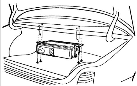
Procedure for installation (suspended position)
1 - Confirm that the built-in anti-vibration boards on both the left and right sides are set to the horizontal installation position "H".
- Attach bracket (L) and bracket (R) using the hexagonal bolts (M5 × 8) .
2-Determine the mounting location and drill four mounting holes.
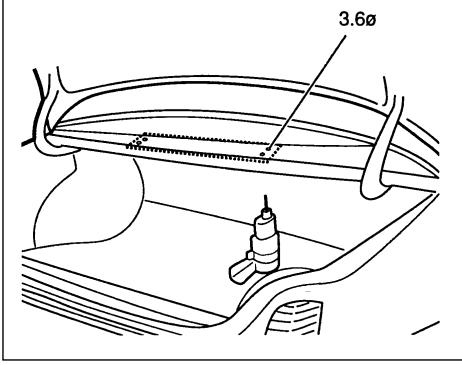
3 - Attach the CD changer with the tapping screws (M5 x 12).
Handling the discs
Dirt, dust, scratches and warpage cause sound skips during playback and a deterioration of sound quality. How to take care of your discs:
- Use compact discs that have the mark shown on the right.

- Fingerprints and dust should be carefully wiped off the disc's signal surface (glossy side) with a soft cloth. Unlike conventional records, the compact disc has no grooves to collect dust and microscopic debris, so gently wiping with a soft cloth should remove most particles. Wipe in a straight motion from the inside to the outside of the disc. Small dust particles or light stains will have absolutely no effect on reproduction quality.
-
Never use such chemicals as record sprays, antistatic sprays or fluid, benzine or thinner to clean compact discs. Such chemicals would irreparably damage the disc's plastic surface.
-
Discs should be put back in their cases after use to avoid serious scratches that could cause sound skip.
- Do not expose discs to direct sunlight, high humidity, or high temperatures for extended periods of time. Long exposure to high temperatures can warp the disc.
- Do not stick paper or write anything with a ball-point pen on the disc surface.
Troubleshooting
Problems which arise because of a bad manipulation of the set or incorrect connections are often wrongly considered to be a malfunction of the set. For this reason, the following table is provided to help you. If the measures listed in the table are not successful, please contact your specialized dealer.
Note any fault messages in the display of your car radio. (See Operating Instructions).
| Symptom | Cause | Remedy |
| No current | Blown fuse. | Replace the fuse with a fuse having the correct current rating. If the fuse blows again, please contact your spe-cialized dealer. |
| Improper connection. | Check connections. | |
| Magazine cannot be installed. | Direction in which it is inserted is wrong. | Insert it in proper direction. |
| CD is not played. | Disc has been loaded upside down. | Load disc with play side facing up. |
| Noise is heard during playback or sound is intermittent. | Large scratches on disc or warped disc. | Compare sound with another disc. If sound from second disc is acceptable, first disc is defective. |
| Extremely dirty disc. | Clean disc. | |
| Transit screws still in place. | Remove screws (x3) on bottom of unit and then use. | |
| Built-in anti-vibration board is installed in wrong direction. | Install board in proper direction. (Refer to “Installation” in Operating |