
EM5010 - Uncategorized BLAUPUNKT - Free user manual and instructions
Find the device manual for free EM5010 BLAUPUNKT in PDF.
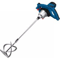


| Product Type | Multimedia Speaker System |
| Brand | Blaupunkt |
| Model | EM5010 |
| Color | Black |
| Dimensions (W x H x D) | 200 x 150 x 100 mm |
| Weight | 1.5 kg |
| Power Supply | AC 230V ~ 50Hz |
| Power Consumption | 15 W |
| Bluetooth Version | 4.2 |
| FM Frequency Range | 87.5 - 108 MHz |
| USB Playback | Yes (MP3, WMA) |
| AUX Input | 3.5 mm stereo jack |
| Remote Control | Included |
| Display Type | LCD with backlight |
| Alarm Clock Function | Yes, with dual alarm and snooze |
| Sleep Timer | Yes, adjustable up to 90 minutes |
| Speaker System | 2.0 stereo, 2 x 5W RMS |
| Output Power (RMS) | 10 W total |
| Impedance | 4 ohms |
| Frequency Response | 50 Hz - 20 kHz |
| Material | Plastic housing with fabric grille |
| Maintenance | Clean with a soft, dry cloth. Do not use abrasives or liquids. |
| Safety | Do not expose to water or moisture. Keep away from heat sources. Use only the supplied power adapter. |
| Spare Parts | Contact Blaupunkt customer service for replacement parts. Remote control, power adapter available. |
| General Information | Manual available in multiple languages. 164-page PDF manual included. |
Frequently Asked Questions - EM5010 BLAUPUNKT
User questions about EM5010 BLAUPUNKT
0 question about this device. Answer the ones you know or ask your own.
Ask a new question about this device
Download the instructions for your Uncategorized in PDF format for free! Find your manual EM5010 - BLAUPUNKT and take your electronic device back in hand. On this page are published all the documents necessary for the use of your device. EM5010 by BLAUPUNKT.
USER MANUAL EM5010 BLAUPUNKT
Enjoy it.
Inflatable mattress
IMPORTANT INFORMATION
To achieve the highest satisfaction, enjoy the product's performance and learn about all its features and functions, please read this manual before using the product.
Before using the device, read the Operating Instructions and comply with its contents. The manufacturer shall not be liable for any damage caused by the use of the device other than for its intended purpose or by improper handling.
Keep these Operating Instructions for future reference.
- This device is for domestic use only. Do not use for any other purposes.
- The device should only be connected to a socket with values corresponding to the values on the rating label.
- It is necessary to check if the total current consumption of all devices plugged into the wall outlet does not exceed the fuse in the circuit.
- If you are using an extension cord, make sure that the total power consumption of the equipment plugged into the extension cord does not exceed the extension cord power rating. Extension cords should be arranged in such a way as to avoid tripping hazards.
- Do not let the cord hang over the edge of a counter, or touch any hot surface.
- The device is not designed to be controlled via an external timer, separate remote control, or other equipment that can turn the device on automatically.
- Before maintenance work, always disconnect the unit from the power supply.
- When unplugging the power cord from the electrical outlet, hold it by the plug only and remove the plug carefully. Never pull the cable as it may cause damage to the plug or power cord. Damage to the power cord or plug can lead to an electrocution hazard.
- Never leave the product connected to the power source without supervision.
- Never put the power cable, the plug, or the whole device into water or any other liquid.
- The device should be cleaned regularly in accordance with the recommendations described in the cleaning and maintenance section.
- Do not place the device near sources of heat, flames, electric heating elements, or hot ovens. Do not place it on any other device.
- This equipment can be used by children aged 8 years and over if they are supervised. People with reduced physical, sensory, or mental capabilities, or those lacking experience and knowledge, must be supervised and instructed regarding the safe use of the equipment and the risks involved. The instruction manual should be used as a reference for safe operation. Children should not play with the equipment. Cleaning and user maintenance should not be performed by children without supervision.
- Extra caution should be exercised when using this device near children or pets. Do not allow children to play with the device.
- Never use the product near combustible materials.
- Never expose the product to atmospheric conditions such as direct sunlight or rain. Never use the product in humid environments (e.g., bathroom or camping trailer).
- The power cable should be checked periodically for damage. If the power cable is damaged, the product should be taken to a professional service center for repair or replacement to prevent hazards.
- Never use the product with a damaged power cable, or if it has been dropped or damaged in any other way, or if it does not operate properly. Do not attempt to repair the defective product yourself, as this may result in electric shock. Always return the damaged device to a professional service center for repair. All repairs should be performed only by authorized service personnel. Any unauthorized repairs
performed can pose a hazard to the user.
- Only use original accessories or those recommended by the manufacturer. Using accessories not recommended by the manufacturer may damage the device and render it unsafe for use.
- Keep your work area clean and well lit. - Cluttered or dark work areas can lead to accidents. - Do not operate power tools in explosive atmospheres, such as in the presence of flammable liquids, gases, or dust.
- A moment of carelessness may cause loss of control of your tool.
- If dust extraction and collection equipment can be attached to the power tool, ensure it is properly connected and used. Using such equipment reduces dust-related hazards.
- Do not overreach when operating the power tool. Maintain proper footing and balance at all times. This enables better control of the power tool in unexpected situations.
- Avoid starting the power tool unintentionally. Make sure the power switch is in the OFF position before connecting the power tool to the mains. Carrying a power tool with your finger on its trigger or plugging in a power tool after switching it on can lead to accidents.
- Wear appropriate clothing. Do not work in loose clothing and do not wear jewellery while working. Keep your hair, clothing and gloves away from moving parts. The moving parts of a power tool can catch and pull in loose pieces of clothing, jewellery or long hair.
- Remove any spanners or tools from the power tool before starting it. A tool or spanner still connected to the rotating part of the power tool may cause personal injury.
- Be careful when working with power tools, concentrate on your work and use common sense. Do not use a power tool
when tired or under the influence of drugs, alcohol or medication. Even a moment of carelessness while working with a power tool can lead to a serious accident.
- Keep children away from the work area and DO NOT allow children to pull on the power cord - this can cause serious injury. • Always place and use the power tool on a stable, level and horizontal surface.
- Before making any adjustments, changing accessories or storing the power tool, move the switch to the off position to disconnect the power tool from the power supply. Such precautions reduce the risk of accidentally starting the power tool.
- Check the grinder housing for damage before each use.
- Ensure that the vents are free from debris. • The device may only be used in a dry, well-lit environment. • This tool should not be used by anyone under the age of 16.
- The device is intended for outdoor use only. Do not use for other than its intended purpose.
- The noise level during operation may exceed 85 dB (A); wear hearing protection.
Electric Mixer - safety warnings.
Mixer and mixing paddle are not intended for the preparation of food for human or animals. You can only mix substances and materials used in construction.
- Unit body and used tools used do not meet the hygiene standards required for food processing.
b) Do not use this equipment to mix flammable or explosive substances.
- During mixer operation, electrical sparks are created in the drive motor, which can lead to ignition of vapours from mixed substances.
c) Before mixing building materials, read their instructions or Material Safety Data Sheet (MSDS).
- Certain types of materials or chemicals pose risks for human health
or life and the process of mixing them may require meeting specified conditions.
d) When mixing materials outside the tank, keep your both hands on insulated power tool grips.
- There is always a risk that concealed live electrical cables may be encountered during works. Sharp edges of some mixers can easily damage or cut electric wires, which can lead to an electric shock.
e) When mixing materials, take care to position the mixer supply line so that it is not close to the rotating working tool (mixing paddle).
- Power cable of your tool must be outside the mixer working area, which may damage or cut it, thus creating a hazard of electric shock.
f) The tank in which the materials are mixed must rest on level and flat ground, so that it will not tilt or wobble while mixing.
- Uncontrolled movement of the tank during mixing can lead to dangerous situations.
g) Hold your power tool firmly and securely with both hands by the insulated grips, while maintaining a stable position.
h) If your power tool becomes very dirty with mixed material, e.g., after falling into the mixing tank, switch off the mixer immediately and disconnect it from the mains.
- Using a power tool into which water or mixture ingredients have entered, can lead to damage to the unit and poses a risk of electric shock.
i) When mixing liquids and fluids, take care to ensure that their droplets do not enter your power tool.
- If liquids or fluids enter the power tool, there is a danger of electric shock.
j) If your working tool (mixing paddle) becomes blocked during mixing, switch off the mixing machine immediately.
While doing so, be cautious of the resulting recoil force, which can pull the equipment out of your hands.
Using faulty working tools, such as crooked mixers, or overloading the equipment can create dangerous situations for the operator.
(k) This mixer is not designed for mounting on racks, supports, etc.
Always hold the unit securely with both hands.
l) Note that changing the speed using the gear selector (gear I or II) must only be carried out with the device switched off.
Changing the speed while the unit is running can damage the machine.
The specified vibration emission value was measured according to standardized procedures and may vary depending on how the power tool is used. In exceptional cases, it may exceed the specified value.
Prolonged exposure to vibration can cause injuries to the operator's hands, such as frostbite. This is mainly a prickling or burning sensation in the fingers, as well as excessive paleness of the hands.
These symptoms indicate that the power tool has been used for too long.
To avoid the risk of adverse vibration effects on your hands, observe a few basic rules:
• Daily working time with the power tool must include regular breaks, during which it is advisable to carry out other activities.
• Perform hand and arm exercises during breaks to improve blood circulation.
• Wear protective gloves to further protect against the negative effects of vibration.
If, despite following the above advice, you feel unwell, e.g., notice finger swelling,
their excessive pale or loss of sensation, immediately seek medical attention.
In addition, you should:
- avoid adopting an uncomfortable position (e.g., through a misaligned balance point) in which your wrists are unnaturally twisted, • take regular breaks to counteract the effect of repetitive loading,
- if you feel any symptoms of hand and arm fatigue or pain, consult the doctor.
Recoil phenomenon:
- This is the sudden, uncontrolled, reaction of the machine to a jammed or blocked work tool. A jam or blockage leads to a sudden stop of the rotating tool, resulting in a violent jerking of the machine.
- Recoil is the result of improper or incorrect use of the unit and failure to follow safety procedures given in the operating manual.
How to prevent the recoil effect:
- Hold your tool firmly and securely, while positioning of your hands and body to prevent the recoil effect from occurring, or mitigate it if it does occur,
- Keep your hands away from rotating work tools.
In the event of any malfunction of the unit, stop its operation immediately and disconnected it from the power source.
Then, check the cause of the failure and, if necessary, return the unit to an authorised service centre.
It is forbidden to use faulty working tools, e.g. crooked or damaged mixers, as this can lead to overloading of the machine with consequent dangerous situations. The mixer is not designed to be permanently fixed to any type of stand, support or rack.
Always hold the device with both hands, with a firm grip on the insulated handle.
Changing the speed using the speed switch must only be done with the unit switched off when the engine is not running.
Changing the speed while the unit is running can damage the
unit.
 | Before starting up, carefully read the operating manual and all safety instructions. |  | Wear protective footwear |
 | The product complies with EC safety standards |  | Use ear protection |
 | Do not expose the unit to rain or moisture. |  | Wear protective gloves |
 | Dispose of the product in accordance with the WEEE directive |  | Wear protective clothing |
 | Wear safety glasses |  | Wear a protective mask |
USE PERSONAL PROTECTIVE EQUIPMENT
- Wear safety glasses according to EN166
- Use protective masks in accordance with EN149
- Use other precision personal protective equipment, depending on the type of work involved.
CE
Device is compliant with EU directives:
- Low voltage directive (LVD)
- Electromagnetic compatibility (EMC) Device marked CE mark on rating label
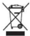
When this crossed-out wheeled bin symbol is attached to a product it means that the product is covered by the European Directive 2012/19/EU. Please inform yourself about the local separate collection system for electrical and electronic products. Used appliance should be delivered to the dedicated collecting points due to hazardous components, which may affect the environment. Do not dispose this appliance in the common waste bin. Environmental information: All unnecessary packaging has been omitted. We have tried to make the packaging easy to separate into three materials: cardboard (box), polystyrene foam (buffer) and polyethylene (bags, protective foam sheet). Your system consists of material which can be recycled and reused if disassembled by a specialized company. Please observe the local regulations regarding the disposal of packaging materials, exhausted batteries and old equipment.

Your product is designed and manufactured with high quality materials and components, which can be recycled and reused.
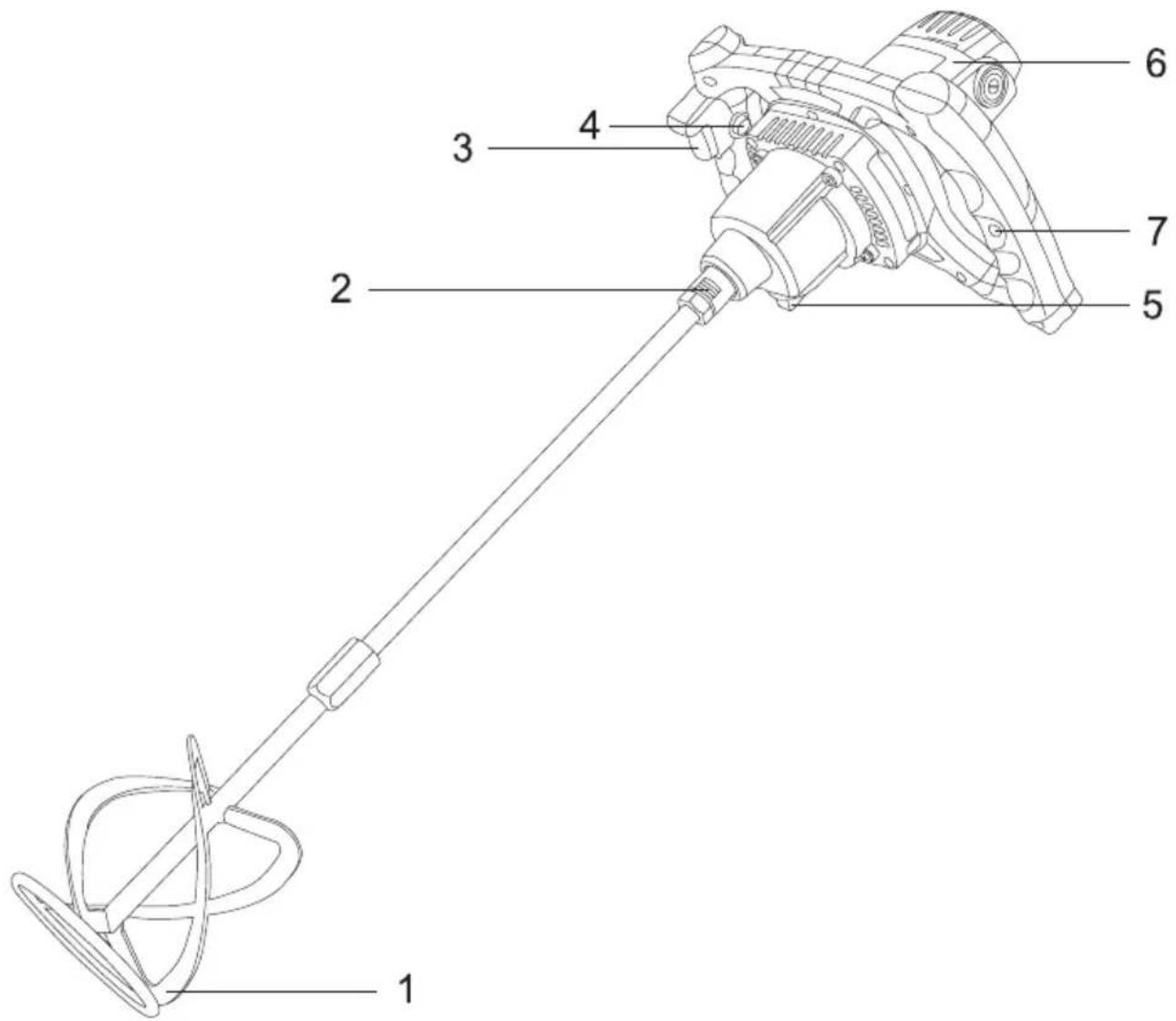
1. Main Parts
- Mixing paddle
- Connection socket for M14 mixing paddles
- ON/OFF switch
- Switch lock knob
- Gear selector
- Motor housing
- Speed control knob
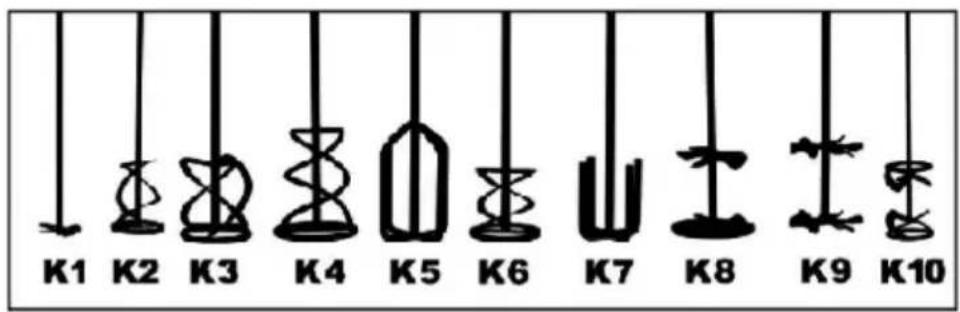
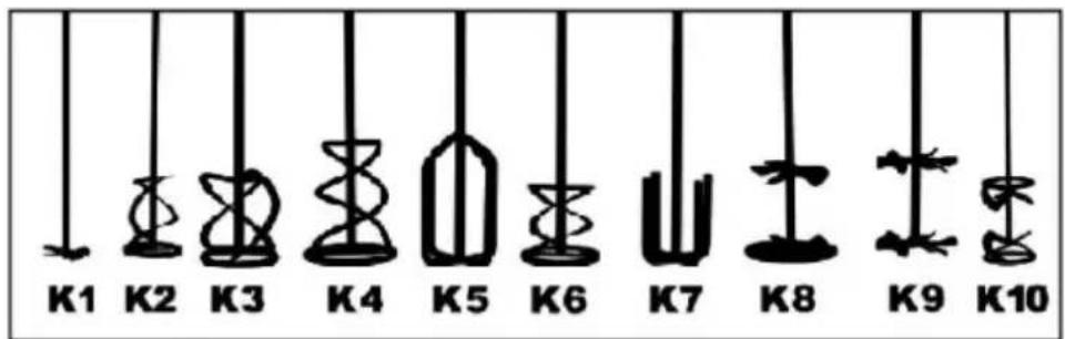
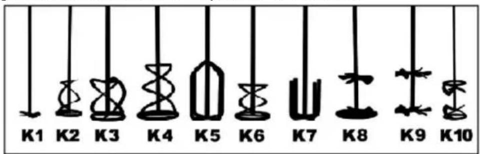
2. Mixing Paddle Selection
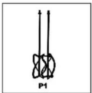
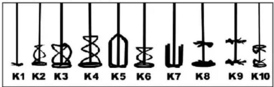
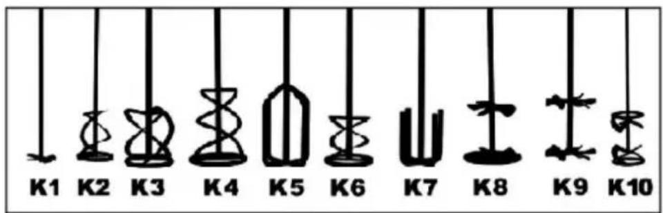
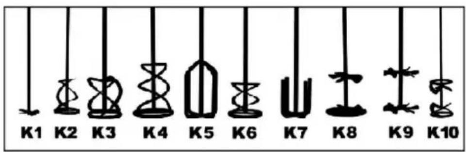
For the unit with a single mixing tool, we supply K3 mixing paddles as standard. You can mount other mixing paddles with M14 threaded connection (K1-K10, etc.).
3. Cleaning and Maintenance
Proper maintenance of the machine can prolong its life. The handle switch must always function properly and must be well maintained. Mixing tools should be cleaned after pouring or if not used for a long time. Usually running water or quartz sand can clean the mixing tools well.
The mixing shaft must always be protected from contamination.
Always place a protective cap over the opening of the hexagonal socket.
Ventilation of the motor housing must not be covered when the machine is running, and there must be no flammable materials near the machine.
Clean the vent frequently.
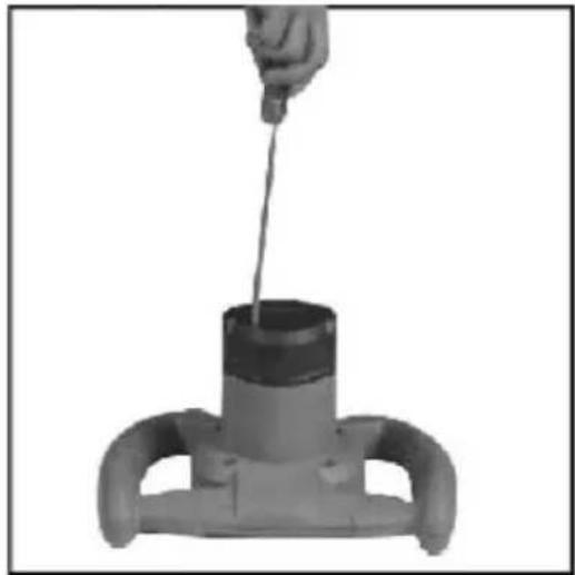
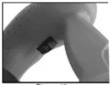
Picture.1
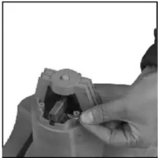
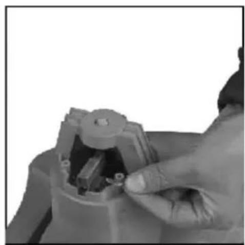
Picture.2
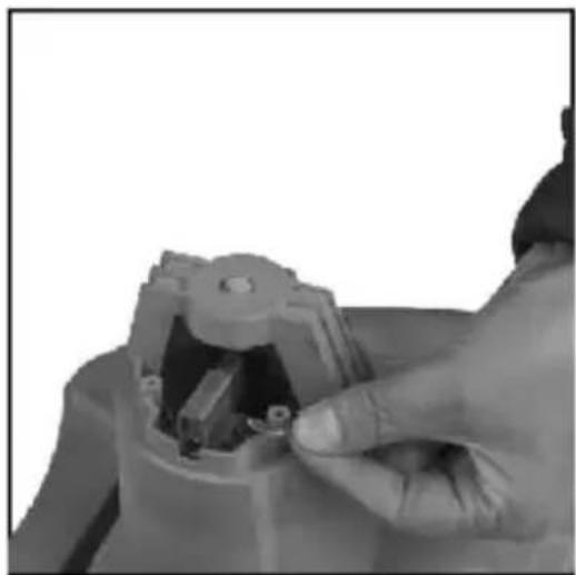
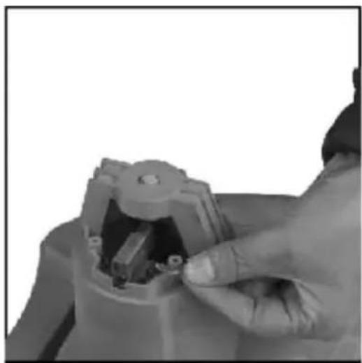
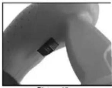
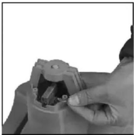
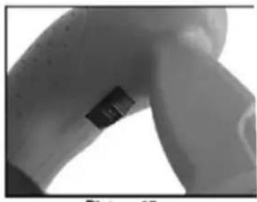
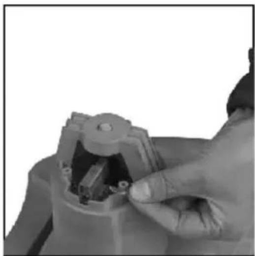
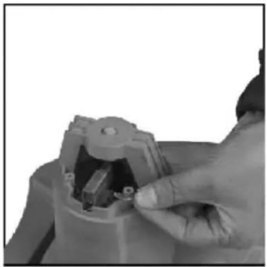
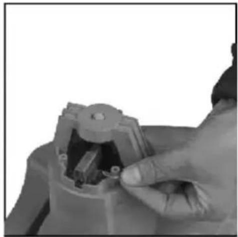
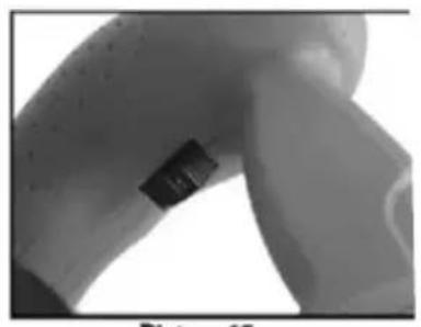
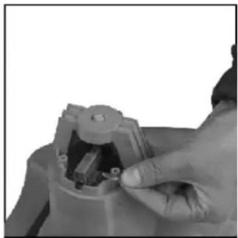
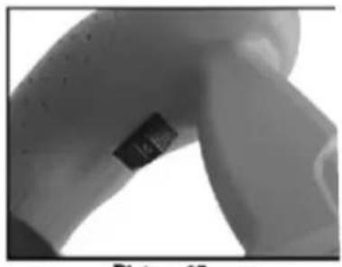
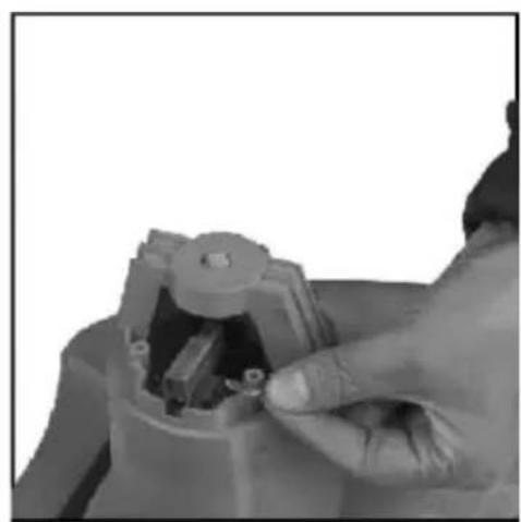
Carbon brush must be checked and maintained when the machine has been in operation for up to 60 hours, the brush must be replaced in time if worn.
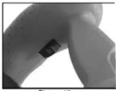
(Pic.1) First disconnect the power supply, dismount the motor housing.
(Pic.2) Remove the plate and replace the carbon brush.
4. Mounting and Operation
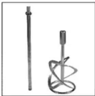
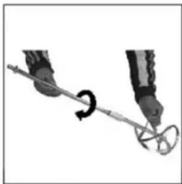
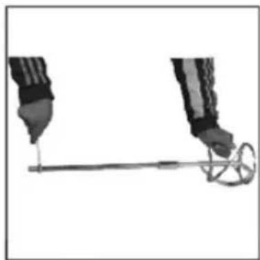
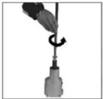
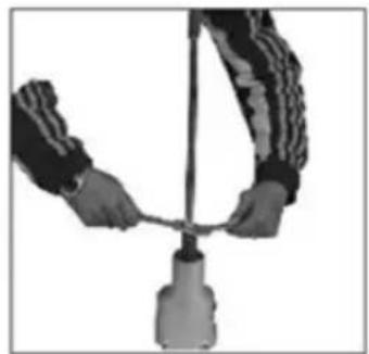
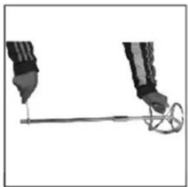
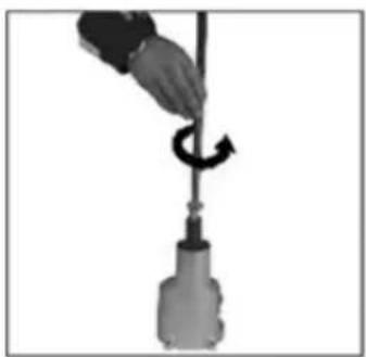
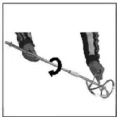
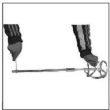
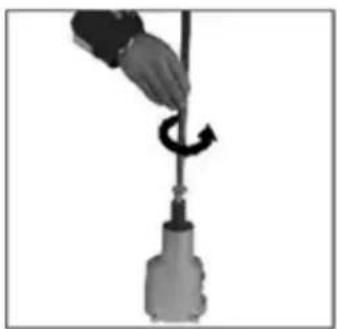
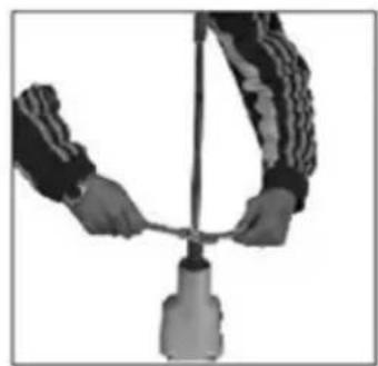
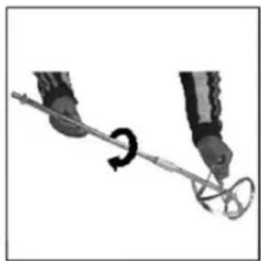
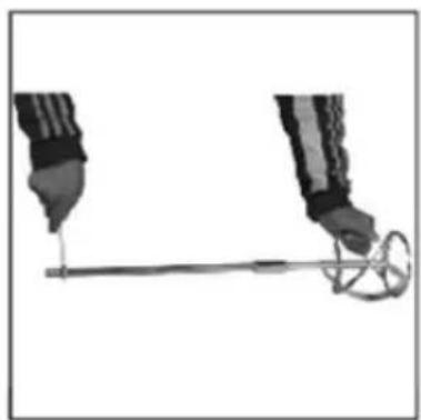
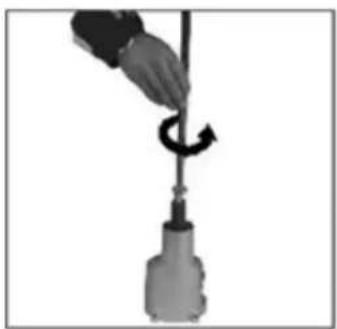
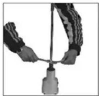
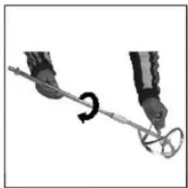
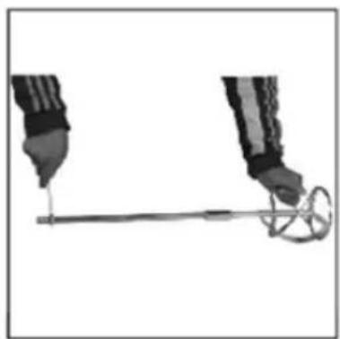
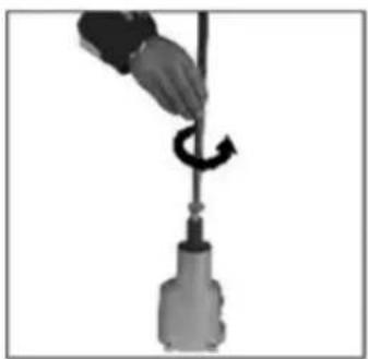
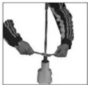
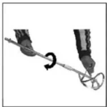
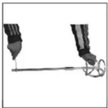
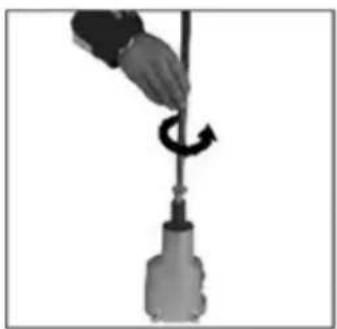
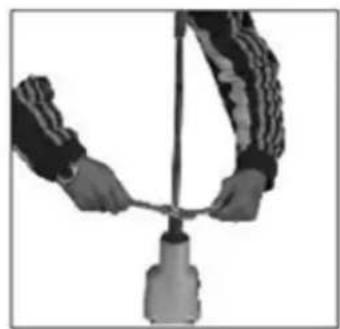
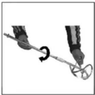
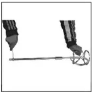
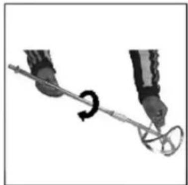
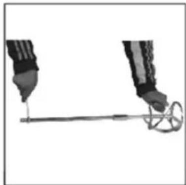
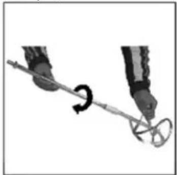
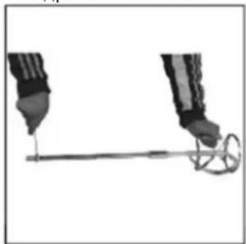
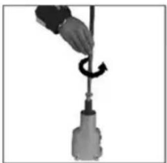
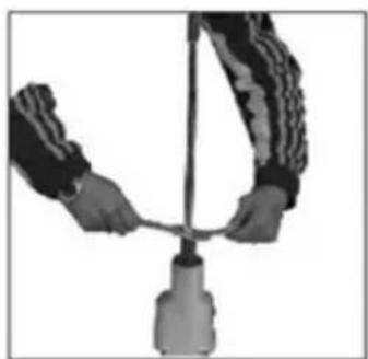
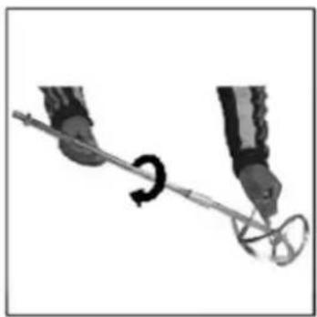
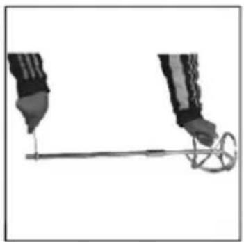
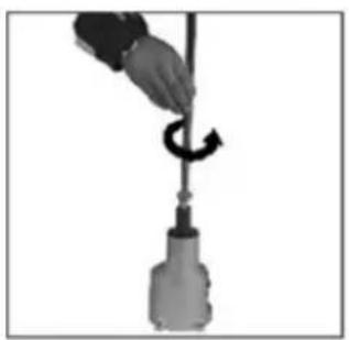
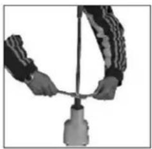
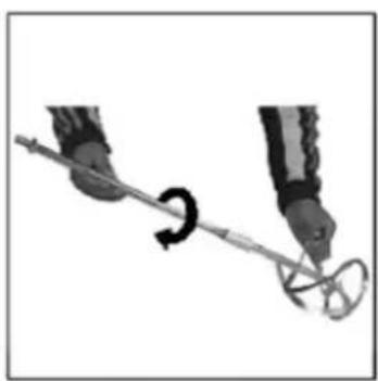
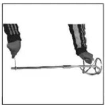
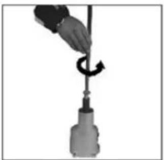
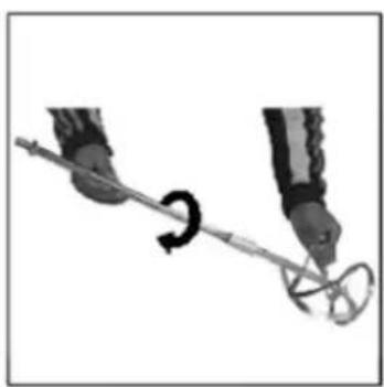
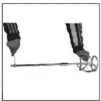
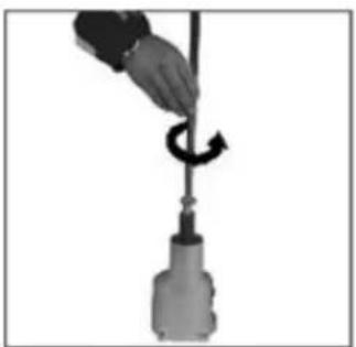
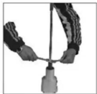
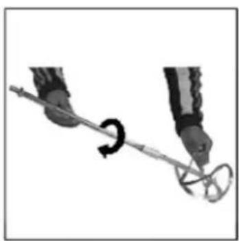
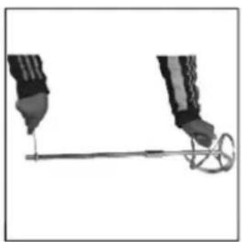
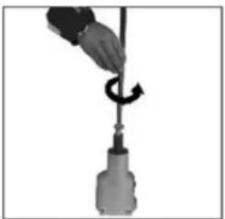
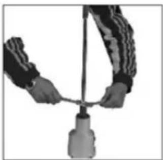
The unit must be fitted with mixing paddles with M14 male threaded connection. Mount the mixing paddle in the machine as follows:
- Disconnect the plug from the mains socket if plugged.
- Turn the unit so that there is free access to the spindle.
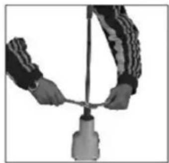
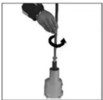
- Insert the end of the mixing paddle - threaded one - into the spindle hole, then tighten.
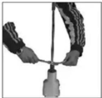
- Holding the spindle with the appropriate spanner, included, securely tighten the mixing paddle.
Picture.1
Picture.2
Picture.3
Picture.4
SPEED CONTROL
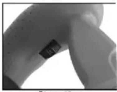
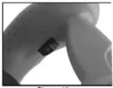
Use the knob (Fig. 7) on the inside of the left grip to change the machine speed.
GEAR CHANGE
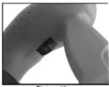
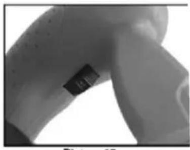
Use the knob (Fig. 6) to change the torque.
When changing the speed range, please note that this operation can only be carried out with the unit switched off. Otherwise, the gears may be damaged - if you feel resistance when changing the gear, turn the spindle slightly so that the gears can mesh.
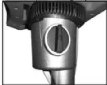
(Picture 6)
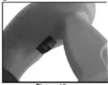
(Picture 7)
SWITCHING ON/OFF
The ON/OFF switch (3) of the machine is located on the right grip and is designed to prevent accidental actuation.
To start your power tool, press the lock (4) and then the switch (3). The machine will switch off when the ON/OFF button (6) is released.
Do not press the switch (6) without first releasing (depressing) the lock (5), as this may damage the unit.
Specifications:
| Model | Em5010 |
| Rated voltage | 230 V~50 Hz |
| Rated power | 1400 W |
| Rated no-load speed | 0-600 rpm 0-900 rpm |
| Mixing diameter | 120 mm |
| Sound pressure level | LpA =92.0dB(A) |
| Sound power level | LWA =103.0dB(A) |
| Uncertainty K | K=3dB(A) |
| Maximum vibration | 3.157m/s2 |
| Uncertainty K | K=1.5m/s2 |
IMPORTANT INFORMATION
2. Selection of the mixing paddle
Picture.1
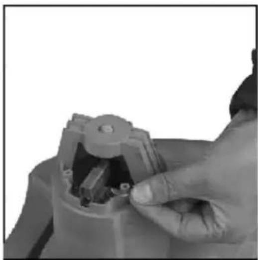
Picture.2
Picture.1
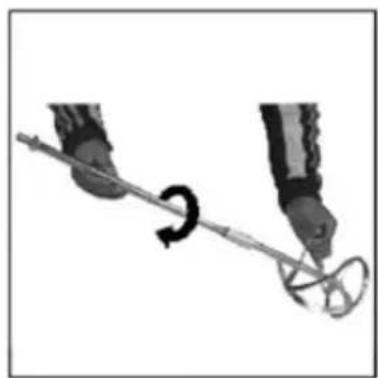
Picture.2
Picture.3
Picture.4
Picture.5
SPEED REGULATION
(Picture 6)
(Picture 7)
ON/OFF
2. selection of the stirrer
Picture.1
Picture.2
Picture.1
Picture 2
Picture 3
Picture 4
Picture 5
SPEED CONTROL
(Picture 6)
(Picture 7)
ON/OFF
USE PERSONAL PROTECTIVE EQUIPMENT
Picture 1
Picture 2
Picture 1
Picture 2
Picture 3
Picture 4
SPEED CONTROL
(Picture 6)
(Picture 7)
On/Off
SPEED CONTROL
(Picture 6)
(Picture 7)
SWITCHING ON/OFF
2. Selecting the mixer
Picture.1
Picture.2
Picture.1
Picture.2
Picture.3
Picture.4
Picture.5
ADJUSTING THE SPEEDS
(Picture 6)
(Picture 7)
SWITCHING ON/OFF
2. Selecting the mixer
3. Cleaning and maintenance of the device
Picture 1
Picture 2
Picture 1
Picture 2
Picture 3
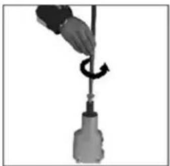
Picture 4
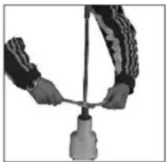
Picture 5
VARIABLE SPEEDS
(Picture 6)
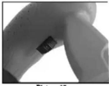
(Picture 7)
ON/OFF
Picture 1
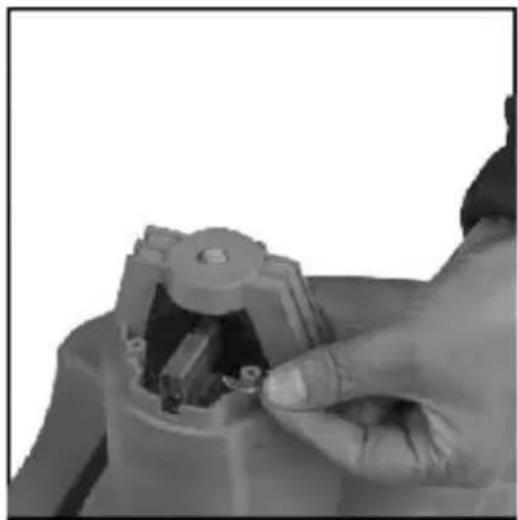
Picture 2
Picture 1
Picture 2
SPEED ADJUSTMENT
(Picture 6)
(Picture 7)
(Picture 6)
(Picture 7)
ON/OFF SWITCH
ADJUSTING THE ROTATION SPEED
(Picture 6)
(Picture 7)
STARTING/STOPPING
2. Selecting the mixer
Picture 1
Picture 2
Picture 3
Picture 4
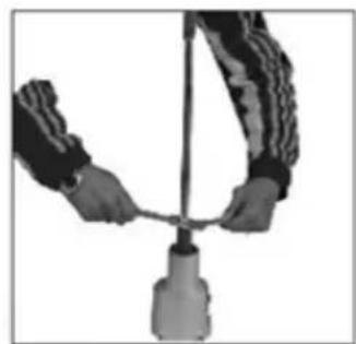
Picture 5
AIR SUPPLY REGULATION
(Picture 6)
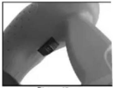
(Picture 7)
SWITCHING ON/OFF
2. Select the value
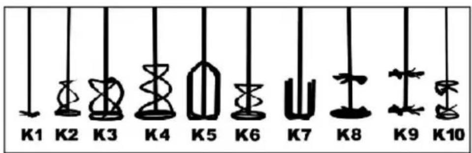
Picture 1
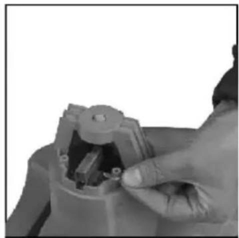
Picture 2
Picture 1
Picture 2
Picture 3
ADJUSTING THE ROTATION SPEED
(Picture 6)
(Picture 7)
SWITCHING ON AND OFF
2. Changing the mixer
3. Cleaning and maintenance
AIR FLOW REGULATION
(Picture 6)
(Picture 7)
ON/OFF
EC – DECLARATION OF CONFORMITY
01/2022/EM5010
MANUFACTURER:
BLAUPUNKT COMPETENCE CENTER
2N-Everpol Sp. z o.o.
ul. Puławska 403A
02-801 Warsaw, Poland
Authorized person to prepare the technical documentation:
Tomasz Jakóbczyk
ul. Puławska 403A
02-801 Warsaw, Poland
We declare under our sole responsibility that our product:
Type of device:
ELECTRIC MIXER
EM5010
If used for its intended use complies with the essential protection requirements relating to the:
2014/30/EU (EMC Directive)
2014/35/EU (LVD Directive)
2006/42/EC (MD Machinery Directive)
2011/65/EU (RoHS Directive) and its Annex II amending directive 2015/863/EU
The assessment of this product has been based on the following standards:
EMC standards:
EN IEC 61000-3-2:2019 + A1:2021
EN 61000-3-3:2013+A1:2019
EN IEC 55014-1:2021
EN IEC 55014-2:2021
MD and LVD standards:
EN ISO 12100:2010
EN 62233:2008
EN 62841-1:2015
EN 62841-2-10:2017
RoHS standards:
EN IEC 63000:2018
Warsaw, 17.08.2022

BLAUPUNKT
Blaupunkt Competence Center 2N-Everpol Sp. z o.o.
Registered office:
Puławska 403A
02-801 Warsaw, Poland
Correspondence address: Puławska 12
05-532 Baniocha, Poland
Phone +48 22 688 08 00
EU DECLARATION OF CONFORMITY
01/2022/EM5010
MANUFACTURER:
BLAUPUNKT COMPETENCE CENTER
2N-Everpol Sp. z o.o.
ul. Puławska 403A
02-801 Warszawa, Polska
02-801 Warsaw, Poland
phone:+48226880800
e-mail: info@everpol.pl
www.blaupunkt.com
In case of questions or problems please contact our service.
Tel. 00 48 22 688 08 33
Email: sda@blaupunkt.pl
Enjoy it.
All rights reserved. All brand names are registered trademarks of their respective owners. Specifications are subject to change without prior notice.



- ENJOY IT
- IMPORTANT INFORMATION
- ELECTRIC MIXER - SAFETY WARNINGS
- USE PERSONAL PROTECTIVE EQUIPMENT
- CE
- MAIN PARTS
- MIXING PADDLE SELECTION
- CLEANING AND MAINTENANCE
- MOUNTING AND OPERATION
- SPEED CONTROL
- GEAR CHANGE
- SWITCHING ON/OFF
- SELECTION OF THE MIXING PADDLE
- SPEED REGULATION
- ON/OFF
- SELECTION OF THE STIRRER
- SELECTING THE MIXER
- ADJUSTING THE SPEEDS
- CLEANING AND MAINTENANCE OF THE DEVICE
- VARIABLE SPEEDS
- SPEED ADJUSTMENT
- ON/OFF SWITCH
- ADJUSTING THE ROTATION SPEED
- STARTING/STOPPING
- AIR SUPPLY REGULATION
- SELECT THE VALUE
- SWITCHING ON AND OFF
- CHANGING THE MIXER
- AIR FLOW REGULATION
- EC – DECLARATION OF CONFORMITY
- BLAUPUNKT COMPETENCE CENTER
- ELECTRIC MIXER
- EM
- BLAUPUNKT
- EU DECLARATION OF CONFORMITY
Brand : BLAUPUNKT
Model : EM5010
Category : Uncategorized