
M0410 - Home trainer HMS Premium - Free user manual and instructions
Find the device manual for free M0410 HMS Premium in PDF.


| Product Type | Home Trainer (Indoor Cycling Bike) |
| Brand | HMS Premium |
| Model | M0410 |
| Dimensions (L x W x H) | Approx. 100 x 50 x 120 cm |
| Weight | Approx. 25 kg |
| Max User Weight | 120 kg |
| Resistance Type | Magnetic Resistance |
| Resistance Levels | 8 levels |
| Display | LCD monitor showing time, speed, distance, calories, pulse |
| Flywheel Weight | 7 kg |
| Pedals | Adjustable with toe cages |
| Seat Adjustment | Vertical and horizontal adjustment |
| Handlebar Adjustment | Vertical adjustment |
| Power Supply | Battery operated (2 x AAA, not included) |
| Maintenance | Clean frame with damp cloth; lubricate chain monthly |
| Safety Features | Stable base with leveling feet; emergency stop |
| Spare Parts Availability | Replaceable pedals, seat, and handlebar grips |
| Warranty | 2 years |
Frequently Asked Questions - M0410 HMS Premium
User questions about M0410 HMS Premium
0 question about this device. Answer the ones you know or ask your own.
Ask a new question about this device
Download the instructions for your Home trainer in PDF format for free! Find your manual M0410 - HMS Premium and take your electronic device back in hand. On this page are published all the documents necessary for the use of your device. M0410 by HMS Premium.
USER MANUAL M0410 HMS Premium
natural_image
Line drawing of a stationary exercise bike with adjustable arms and legs (no text or symbols)UWAGI DOTYCZĄCE BEZPIECZEŃSTWA
Diagram montażowy
Instrukcja montażu
Przygotowanie
Rysunek 1
Rysunek 2
Rysunek 3
Rysunek 4
Wybór programu
natural_image
Solid blue background with a small white rectangular shape in the top-left corner (no text or symbols)Rysunek 29
natural_image
Solid blue background with a single white horizontal line in the center (no text or symbols)Rysunek 30
natural_image
Solid blue background with three white square bullet points in the bottom row (no text or symbols)Rysunek 31
Rysunek 32
Rysunek 33
natural_image
Blue background with a white plus sign in the center (no text or symbols)Rysunek 34
iConsole+
Krok 2.
Krok 6.
Ćwicz z Google Street View
Instrukcja treningu
1. Rozgrzewka
natural_image
Line drawing of a person performing a stationary exercise on a scooter (no text or symbols)natural_image
Blank white image with no visible content, text, or symbolsIMPORTANT SAFETY INFORMATION
This product has been designed for home use only and built for optimum safety. Please note the following safety precautions:
-
Before starting any exercise program you should consult your doctor to determine if you have any physical or health conditions that could create a risk to your health and safety, or prevent you from using the equipment properly. Your doctor's advice is essential if you are taking medication that affects your heart rate, blood pressure or cholesterol level. This is especially important for persons over the age of 35, pregnant women, or those with pre-existing health problems or balance impairments.
-
Before using this equipment to exercise, always do stretching exercises to properly warm up.
-
Be aware of your body's signals. Incorrect or excessive exercise can damage your health. Stop exercising if you experience any of the following symptoms: pain, tightness in your chest, irregular heartbeat, extreme shortness of breath, feeling light headed, dizzy or nauseous. If you do experience any of these conditions you should consult your doctor before continuing with exercise program. Injuries to health may result from incorrect or excessive training.
-
During exercises and after keep children and pets away from the equipment.
-
Use the equipment on a solid, flat level surface with a protective cover for your floor or carpet. Move all sharp objects.
-
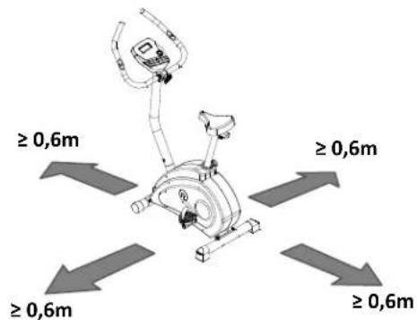
Free area shall be not less than 0,6 m greater than the training area in the directions from which the equipment is accessed. Free area must also include the area for emergency dismount. Where equipment is positioned adjacent to each other the value of the free area may be shared.
-
Before each use, visually inspect the unit including hardware and resistance bends.
-
Before using the equipment, check if the nuts, bolts and other bends are securely tightened.
-
Always use the equipment as indicated. If you find any defective components whilst assembling or checking the equipment, or if you hear any unusual noise coming from the equipment while using, stop. Do not use the equipment until the problem has been rectified.
-
Do not insert any object into any openings.
-
Be aware of all regulation and constructions parts which may disturb during exercises.
-
The safety level of the equipment can only be maintained if it is regularly examined for damage and/or wear and tear.
-
Wear suitable clothing whilst using the equipment. Avoid wearing loose clothing which may get caught in the equipment or that may restrict or prevent movement.
-
The equipment has been tested and certified according to EN ISO 20957-1 under class H. It is not suitable for therapeutic use.
-
Care must be taken when lifting or moving the equipment so as not to injure your back. Always use proper lifting techniques and/or use e assistance.
-
The equipment is designed for adult use only. Keep unsupervised children a way from the equipment.
-
Assemble this unit as described in this manual. Use only parts from the set. Check all parts with the part list.
WARNING: READ ALL INSTRUCTIONS BEFORE USING ANY FITNESS EQUIPMENT. WE ASSUME NO RESPONSIBILITY FOR PERSONAL INJURY OR PROPERTY DAMAGE CAUSED BY OR THROUGH THE USE OF THIS PRODUCT
SPECIFICATIONS
Weight - 26,7 kg
Flywheel - 6 kg
Dimensions - 98,5 x 56 x 135 cm
Maximum weight of user - 150 kg
MAINTENANCE
Your unit has been carefully designed to require minimum maintenance. To ensure this, we recommend that you do the following: keep your unit clean by wiping sweat, dust or other residue off with a soft, clean cloth after each use. Always make sure that the bands are secure and show no signs of wear. Regularly check the tightness of nuts and bolts.
BREAKING
Stop to pedal when you want stop the item. Elliptical bike M0410 does not acquire breaking system or emergency break
TENSION ADJUSTMENT
To reduce or increase tension press dedicated buttons on the computer.
Parts list
| No. | DESCRIPTION | Quantity | No. | DESCRIPTION | Quantity |
| 1 | Main frame | 1 | 40 | Cover (L) | 1 |
| 2 | Computer pos t | 1 | 41 | Cover hous ing | 1 |
| 3 | Handle bar tube | 1 | 42 | Crank hous ing | 2 |
| 4 | Saddle tube | 1 | 43 | Carriage s crew M8*74 | 4 |
| 5 | Adjust wheel bus hing | 1 | 44 | Screw M8*20 | 4 |
| 6 | Adjust wheel fixed piece set | 1 | 45 | Screw M4*20 | 4 |
| 7 | Adjust wheel ga p washer | 1 | 46 | Nut cap M8*1.25*15.5T | 4 |
| 8 | Sink wa sher | 1 | 47 | Nylon cap M10*1.5*10T | 3 |
| 9 | Pedal (L) | 1 | 48 | M8 arc washer (OD20*ID8.5*1.5T) | 8 |
| 10 | Saddle knob | 1 | 49 | Flat washer OD20*ID10.5*2.0T | 5 |
| 11 | 板 Pedal® | 1 | 50 | M8*2.0T spring washer | 9 |
| 12 | Tube end cap | 2 | 51 | Screw M4*16 | 13 |
| 13 | Crank | 1 | 52 | M10*6.35T Nylon cap | 1 |
| 14 | Transformer | 1 | 53 | Computer | 1 |
| 15 | Belt pl ate | 1 | 54 | Hand pulse | 2 |
| 16 | Belt | 1 | 55 | Sensor wire upper | 2 |
| 17 | Flywheel | 1 | 56 | Sensor wire lower | 1 |
| 18 | Flywheel axle | 1 | 57 | Computer fixed screw | 4 |
| 19 | 6904 bea ring | 1 | 58 | Handle pulse screw | 2 |
| 20 | 6001 bea ring | 1 | 59 | Round shape inductor(include sens or fixed seat) | 1 |
| 21 | One way bearing HF2016 | 1 | 60 | Handle pulse wire | 2 |
| 22 | Small belt wheel | 1 | 61 | Front stabilizer | 1 |
| 23 | One way axle housing | 1 | 62 | Rear stabili zer | 1 |
| 24 | 6901 bea ring | 1 | 63 | OD20*ID8.5*2.0T flat washer | 1 |
| 25 | Cs hape button (match § 12 axle) | 2 | 64 | Flat washer OD12*8.5*1.5T | 1 |
| 26 | Adjust wheel | 1 | 65 | Handle bar knob bushi ng | 1 |
| 27 | Adjust wheel spring | 1 | 66 | Flat washer OD14*ID10.5*1.5T | 1 |
| 28 | Motor | 1 | 67 | Power supply wire | 1 |
| 29 | Motor steel wire | 1 | 68 | Screw M10*100 | 1 |
| 30 | Saddle | 1 | 69 | Magnet control piece set | 1 |
| 31 | Saddle tube knob | 1 | 70 | M5 nut | 2 |
| 32 | Saddle bushing | 1 | 71 | Screw M5*30 | 1 |
| 33 | Handle bar foam | 2 | 72 | Magnet control piece spring | 1 |
| 34 | Handle bar knob | 1 | 73 | Cut fitting s et 10 pcs | 1 |
| 35 | Handle bar housing | 1 | 74 | Saddle fixed piece set | 1 |
| 36 | Handle bar tube end cap | 2 | 75 | M8 nylon cap | 4 |
| 37 | Front moving wheel tube end cap | 2 | 76 | M8 spring washer | 4 |
| 38 | Rear stabili zer adjust end cap | 2 | 77 | M8 flat was her | 4 |
| 39 | Cover (L) | 1 |
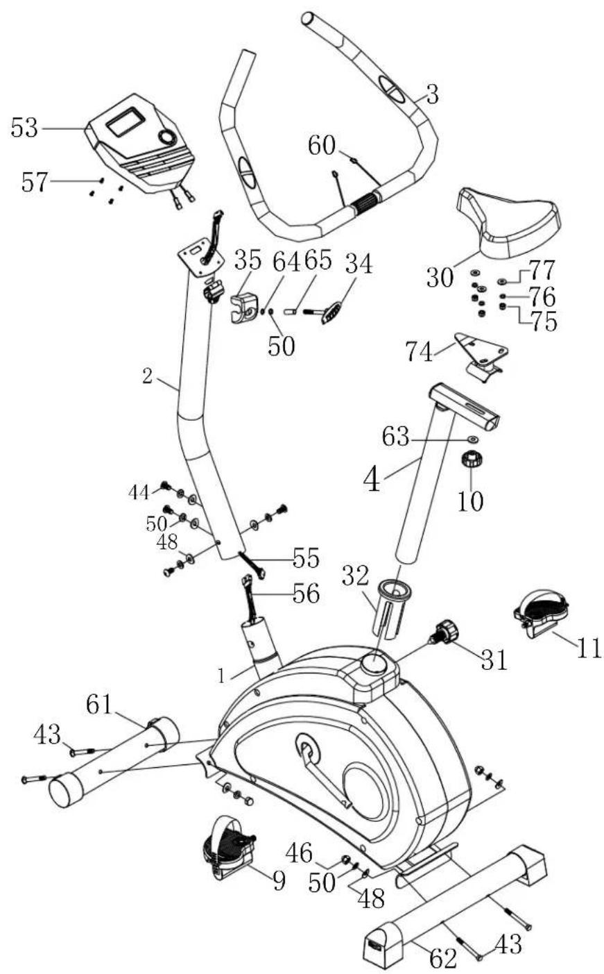
Exploded View
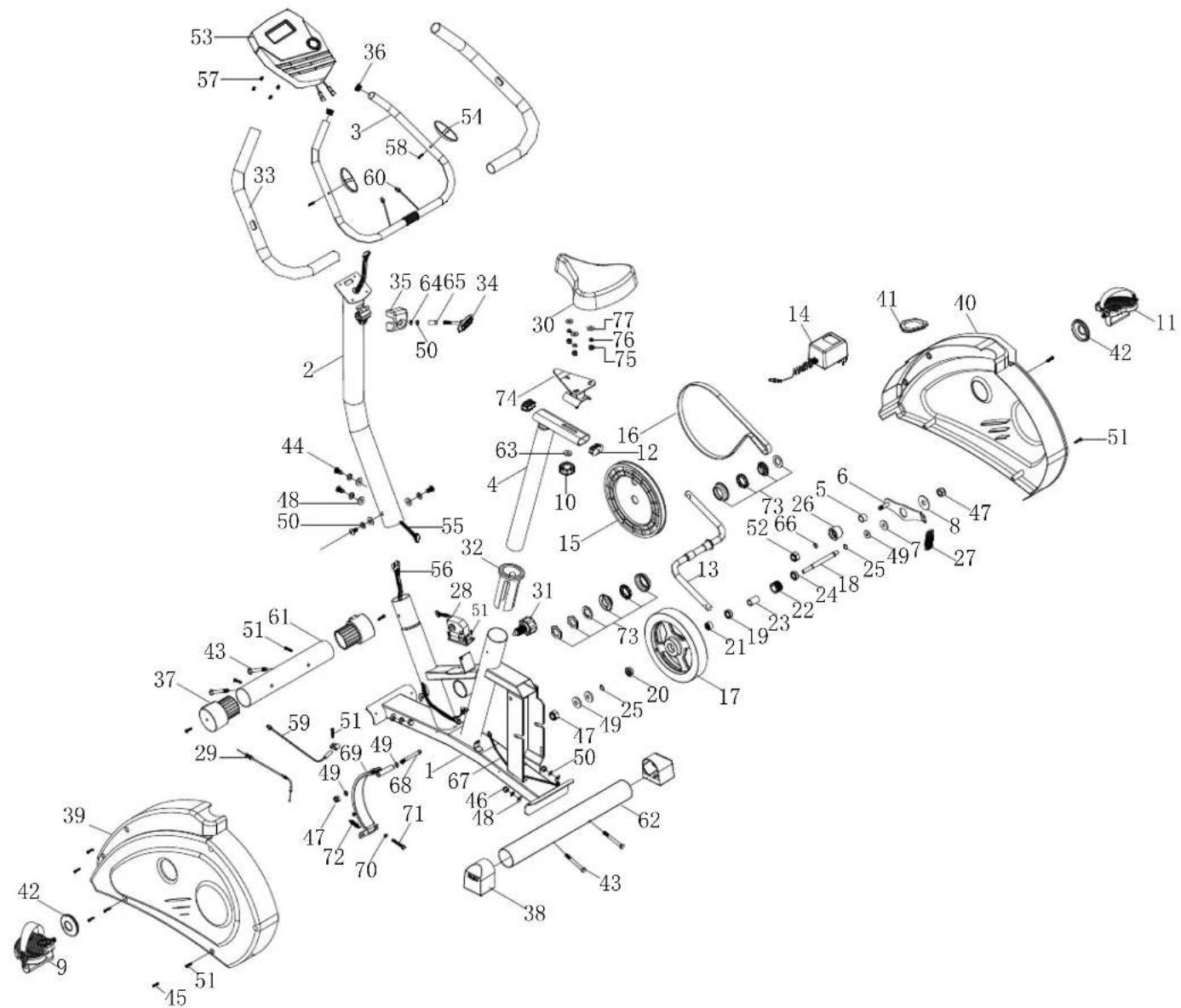
Assembly Diagram
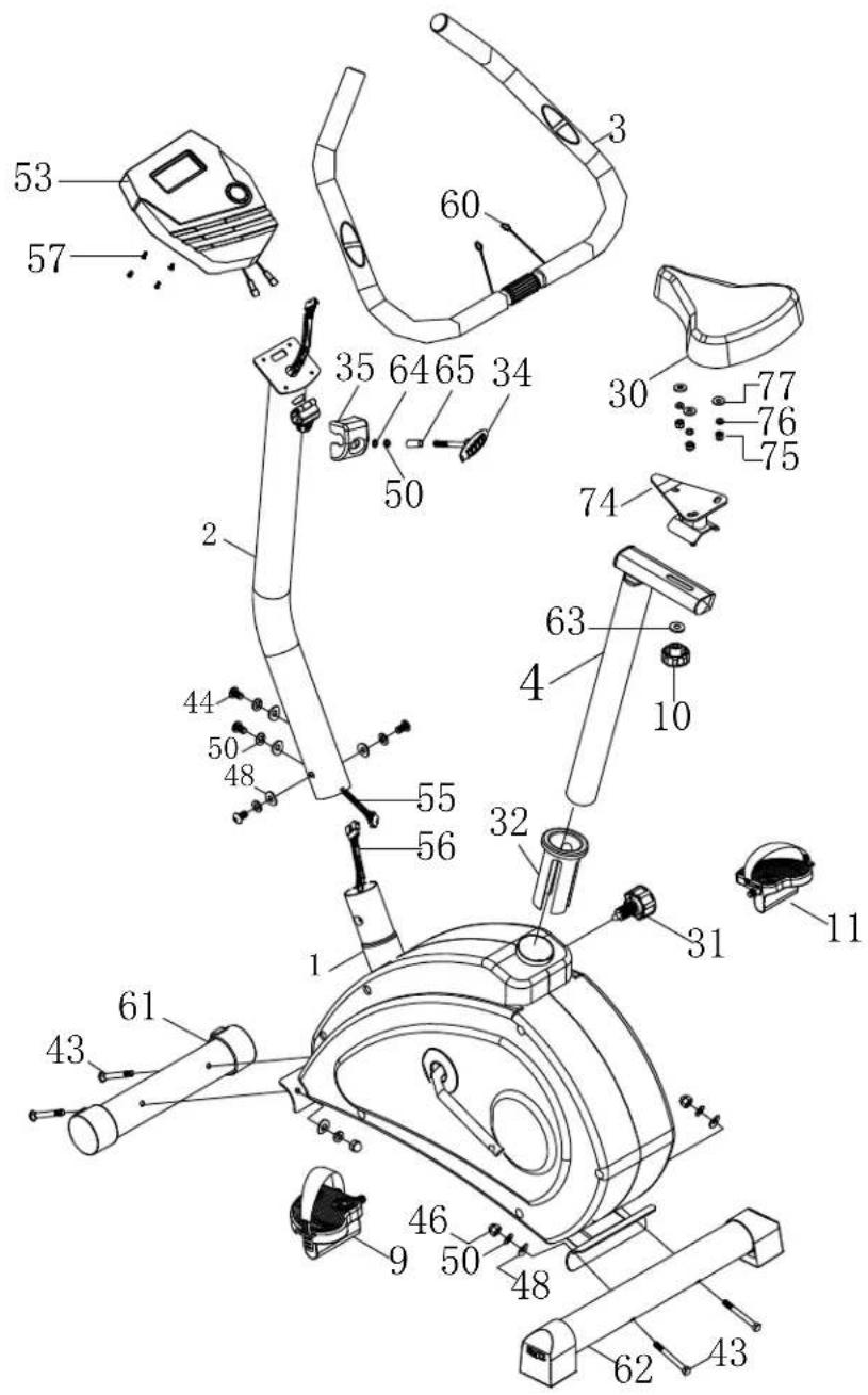
Assembly:
Preparation
1) Before assembling make sure that you have enough space for assembling the item
2) Before assembling please check whether all needed parts are available (at the above of this instruction on sheet you will find an explosion drawing with all single parts marked with numbers) which this item consists of.
3) Use the present tooling for assembling.
Assembly process
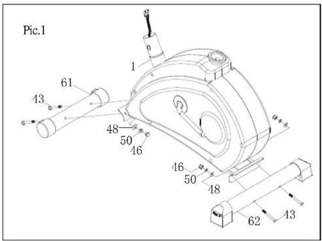
STEP 1. Front stabilizer and rear stabilizer
Attach the front stabilizer (61) to the main frame (1). Insert 2pcs of M8*74 carriage screw (43) through the front stabilizer (61) and the front arc plate of main frame, then use 2pcs of M8 arc washer (48), M8 spring washer (50) and M8 nut (46) to lock this group up.
Attach the rear stabilizer (62) to the main frame (1). Insert 2pcs of M8*74 carriage screw (43) through the rear stabilizer (62) and the rear arc plate of main frame, then use 2pcs of M8 arc washer (48), M8 spring washer (50) and M8 nut (46) to lock this group up.
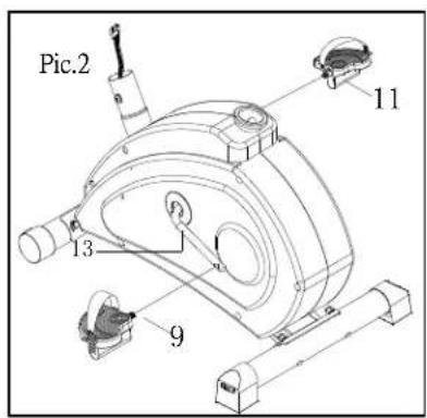
STEP 2. Pedals
Attached the left pedal (9) with bandage to the left crank (13), screw it anti-clockwise till it is tight.
Attach the right pedal (11) with bandage to the right crank (13), screw it clockwise till it is tight.
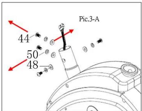
STEP 3. Computer post
Firstly please remove the 4 pcs of M8*20 screws (44), M8 spring washers (50), M8 arch washers (48) which were pre-assembled on the computer post. Pic 3-A
Then Move the computer pole set(2) to the lower computer pole of the main body(1), connect the sensor wire upper (55) and sensor wire lower(56), cover the computer pole (2) to the lower computer pole. Finally, use the removed 4 pcs of M8*20 screws (44), M8 spring washers (50), M8 arch washers (48) to lock them up.
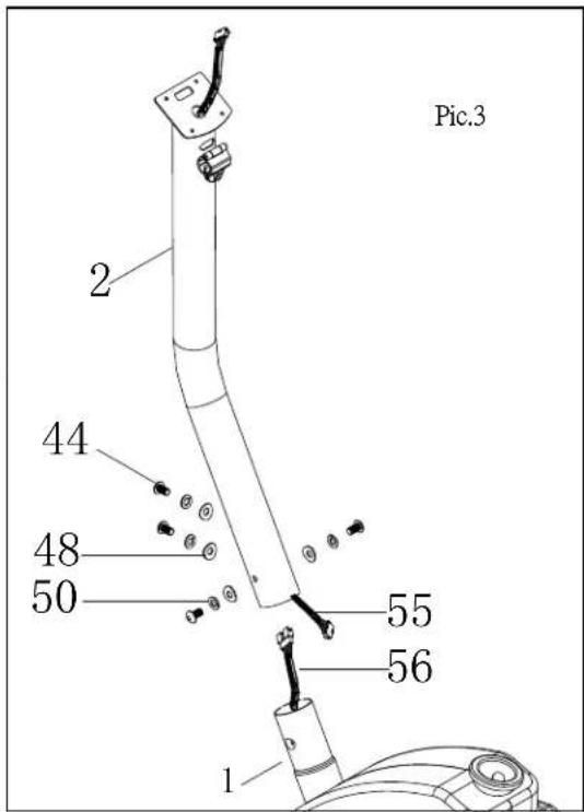
STEP 4. Handle bar
Move the handle bar tube (3) to the computer Pole (2), insert the handle pulse wire (60) to the hole of the head of computer pole (marked by red circle) and make it out of the computer fixed piece.
Use the head of the computer pole(2) to block the handle bar tube(3), cover it with handle bar housing(35), use handle bar knob(34) to transfer handle bar knob bushing(65), M8 spring washer(50) and flat washer D12*ID8.5*1.5T(64), then make the handle bar tube (3) and handle housing(35) fixed onto the computer pole(2) and fasten them.
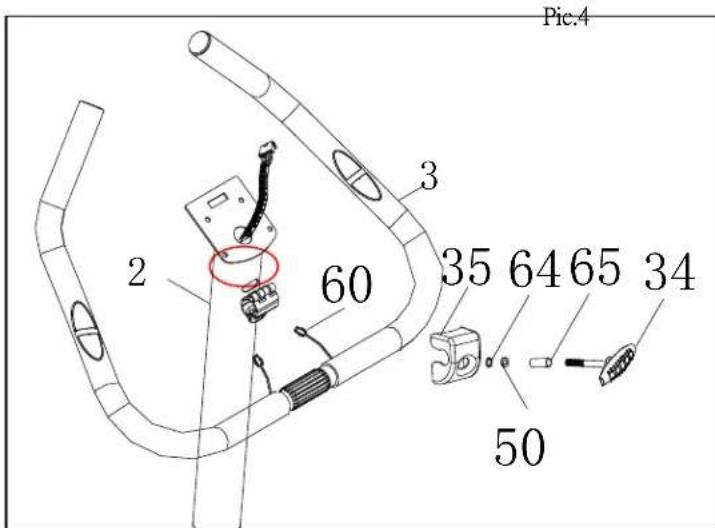
STEP 5. Computer
Remove the computer screws (57) which were pre-assembled on the computer (53)
Connect the handle pulse connection(60) which is out of the computer pole to the handle pulse connection (A) which is out of the computer.
Insert the sensor wire upper(55) to the insert hole of the sensor wire which is on the back of the computer.
Then block the computer(53) to the computer fixed piece of thecomputer pole(2), fasten them with removed computer screws(57).
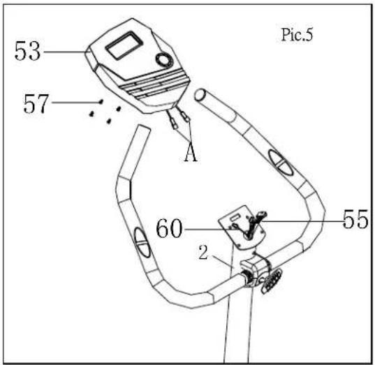
STEP 6. Seat
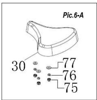
Remove the M8 nylon cap (75), M8 spring washer (76), and M8 flat washer (77) out of the pre-assembled seat (30). Pic 6-A.
Insert the screws of saddle(30) to screw hole of the seat tube fixed piece(74), fasten them with removed M8 nylon cap, M8 spring washer(76) and M8 flat washer(77).
Then attach the saddle fixed piece(74) with saddle(30) to the seat tube set(4), fasten them with flat washer OD20*ID8.5*2.0T (63) and saddle knob(10), fix them.
Insert the seat tube set(4) with saddle and saddle fixed piece to the main frame, adjust to the ideal height and lock them with seat tube knob(31).(Because seat tube set (4) can move freely in the main frame seat tube of the main body, seat tube knob (31) has to transfer the hole of the seat tube set(4) and be fasten.)
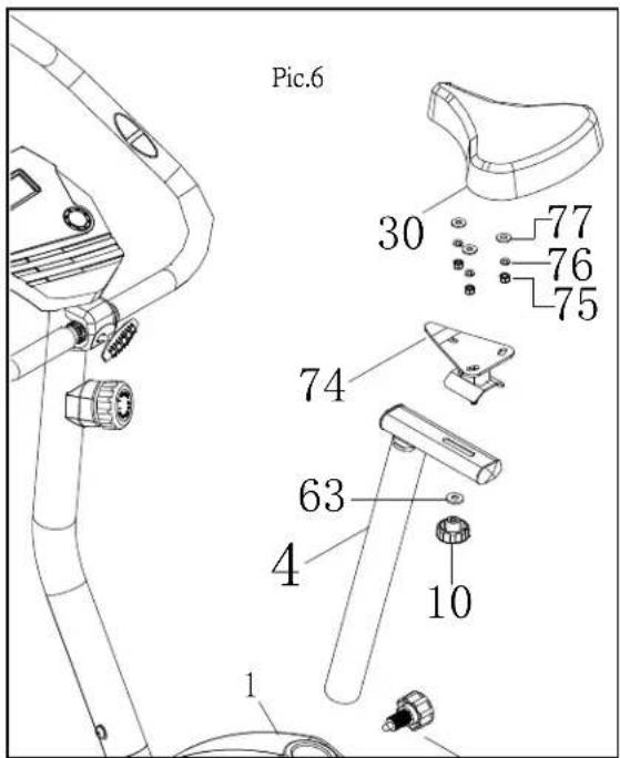
Computer
Display functions
| ITEM | DESCRIPTION |
| SPEED | Workout speed displayed during exercise. Range 0.0 ~ 99.9 |
| RPM | Rotation per minute Range 0 ~ 999 |
| TIME | Workout time displayed during exercise. Range 0:00 ~ 99:59 |
| DISTANCE | Workout distance displayed during exercise. Range 0.0 ~ 99.9 |
| CALORIES | Burned calories during workout display. Range 0 ~ 999 |
| WATT | Workout power consumption Display range 0~350 |
| PULSE | Pulse bpm displayed during exercise. Pulse alarm when over preset target pulse. |
| MANUAL | Manual mode workout. |
| PROGRAM | 12 PROGRAM selection. |
| H.R.C | Target HR training mode. |
| WATTS | WATT constant training mode. |
| USER | User creates resistance level profile |
Key function
| ITEM | DESCRIPTION |
| Up | Increase resistance levelSetting selection. |
| Down | Decrease resistance levelSetting selection. |
| Mode | Confirm setting or selection. |
| Reset | Hold on pressing for 2 seconds, computer will reboot and start from user setting.Reverse to main menu during presetting workout value or stop mode. |
| Start/ Stop | Start or Stop workout. |
| Recovery | Test heart rate recovery status. |
| Body fat | Test body fat% and BMI. |
Operation procedure
POWER ON
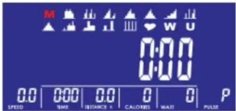
Plugin power supply, computer will power on and display all segments on LCD for 2 seconds (Drawing 1).
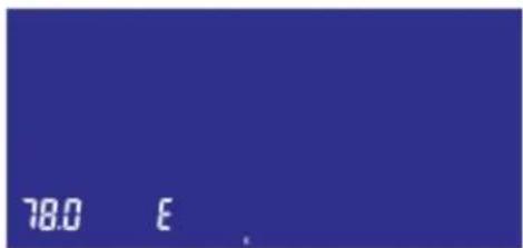
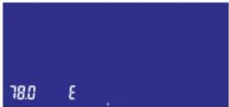
Then display preset wheel diameter in SPEED window and "E" or "A" in TIME window for 1 second
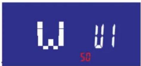
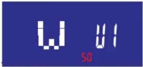
(Drawing 2). Then enter into User data setting. Press joggle wheel to select U1\~U4, then set SEX,AGE, HEIGHT,WEIGHT (Drawing
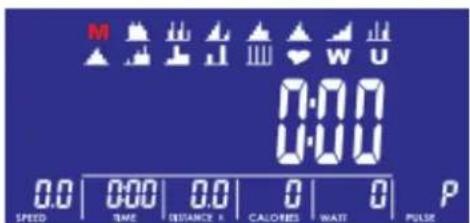
3) and confirm by MODE button. When finishing user data profile, console come to main menu (Drawing 4).
After 4 minutes without pedaling or pulse input, console will enter into power saving mode.
Press any key may wake the console up.
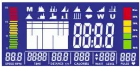
Drawing 1
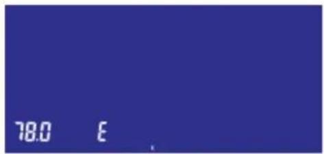
Drawing 2
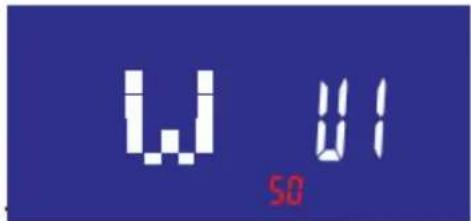
Drawing 3
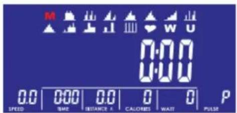
Drawing 4
WORKOUT SELECTION
In main menu, press joggle wheel UP or DOWN to select workout: M(Manual) (Drawing 4)→P(Program 1-12) (Drawing 5)→ ♥ (H.R.C) (Drawing 6) → W(WATTS)(Drawing 7) → U(User)(Drawing 8), press MODE to enter.
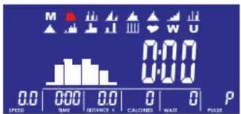
Drawing 5
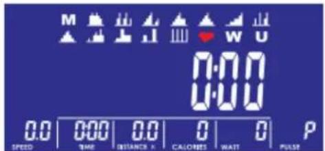
Drawing 6
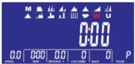
Drawing 7
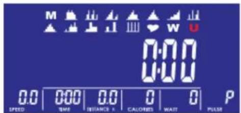
Drawing 8
Manual Mode
Press START in main menu may start workout in manual mode directly.
- Press joggle wheel UP or DOWN to select workout program, choose M and press MODE to enter.
- Press UP or DOWN to adjust load level (Drawing 9), preset value 1.
- Press UP or DOWN to preset TIME (Drawing 10), DISTANCE (Drawing 11), CALORIES (Drawing 12), PULSE (Drawing 13) and press MODE to confirm.
- Press START/STOP keys to start workout. During workout, user can also adjust load level by pressing joggle wheel. Load level display in WATT window, no adjusting for 3s, it will switch to display WATT (Drawing 14).
- Press START/STOP keys to pause workout. Press RESET to reverse to main menu.
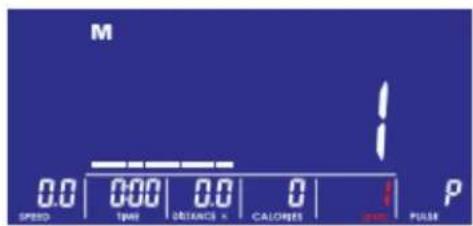
Drawing 9
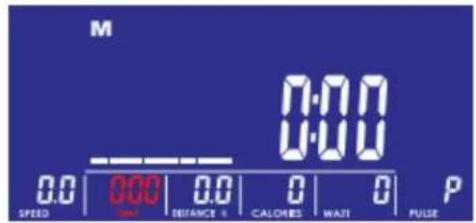
Drawing 10
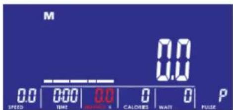
Drawing 11
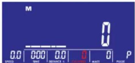
Drawing 12
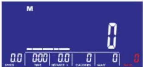
Drawing 13
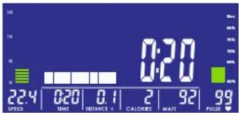
Drawing 14
Program Mode
- Press joggle wheel UP or DOWN to select workout Program, choose P01 (Drawing 15), P02, P03, ...P12. and press MODE to enter.
- Press joggle wheel UP or DOWN to adjust load level (Drawing 16), preset value 1.
- Press joggle wheel UP or DOWN to preset TIME.
- Press START/STOP key to start workout. During workout, user can also adjust load level by pressing joggle wheel.
- Press START/STOP key to pause workout. Press RESET to reverse to main menu.
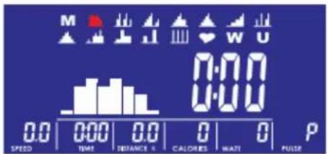
Drawing 15
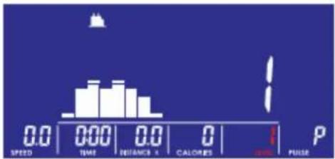
Drawing 16
H.R.C Mode
- Press joggle wheel UP or DOWN to select workout program, choose H.R.C. and press MODE to enter.
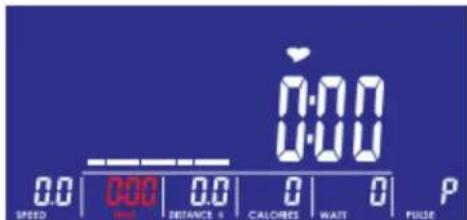
- Press joggle wheel UP or Down to select 55%(Drawing 17), 75%(Drawing 18), 90% (Drawing 19) or TAG (TARGET H.R., default: 100) (Drawing 20). When select TAG, press joggle wheel to set value 30\~230.
- Press joggle wheel UP or DOWN to preset workout TIME (Drawing 21).
- Press START/STOP key to start or stop workout. Press RESET to reverse to main menu.
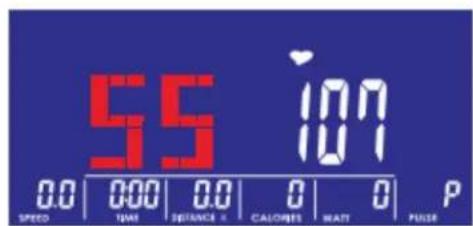
Drawing 17
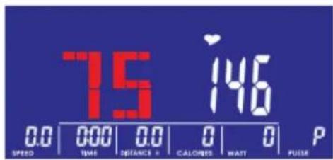
Drawing 18
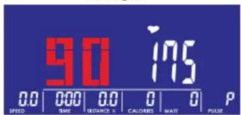
Drawing 19
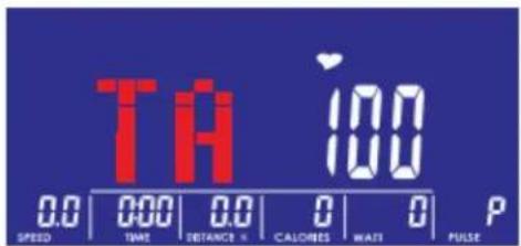
Drawing 20
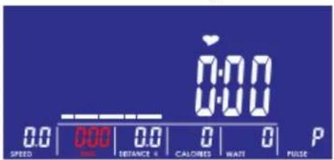
Drawing 21
Watt Mode
- Press joggle wheel UP or DOWN to select workout program, choose W and press MODE to enter.
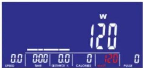
- Press joggle wheel UP or DOWN to preset WATT target. (default: 120, Drawing 22)
- Press joggle wheel UP or DOWN to preset TIME (Drawing 23).
- Press START/STOP key to start workout. During workout, system will adjust load level automatically based on user training status. User can press joggle wheel to adjust Watt level.
- Press START/STOP key to pause workout. Press RESET to reverse to main menu.
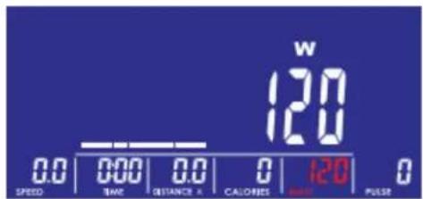
Drawing 22
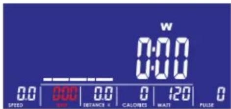
Drawing 23
User Program Mode
- Press joggle wheel UP or DOWN to select workout program, choose U and press MODE to enter.
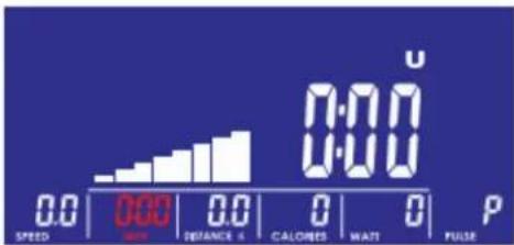
- Press joggle wheel UP or DOWN to create user profile (Drawing 24). There are total 8 column, user can adjust each column load level. User can hold MODE 2s to quit during setting.
- Press joggle wheel UP or DOWN to preset TIME (Drawing 25).
- Press START/STOP key to start workout. During workout, user can also adjust load level by pressing joggle wheel.
- Press START/STOP key to pause workout. Press RESET to reverse to main menu.
Drawing 24
bar
| Parameter | Value | |---|---| | SPEED | 0.0 | | AIR | 0.0 | | DISTANCE 6 | 0.0 | | CALORIES | 0 | | WAIT | 0 | | PULSE | 0 |Drawing 25
Recovery
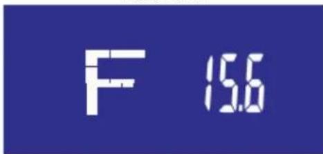
After exercising for a period, keep holding on hand grips or wearing chest strap and press RECOVERY button. All function display will stop except "TIME" starts counting down from 00:60 to 00:00 (Drawing 26). Screen will display your heart rate recovery status with the F1, F2....to F6 (Drawing 27). F1 is the best, F6 is the worst. User may keep exercising to improve the heart rate recovery status. (Press the RECOVERY button again to return the main display.)
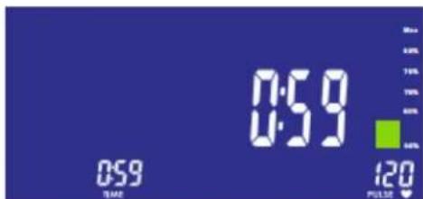
Drawing 26
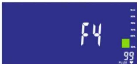
Drawing 27
Body fat
- In STOP mode, press the BODY FAT button to start body fat measurement.
- Console will display UX (Drawing 28) and start measuring (Drawing 29\~30).
- During measuring, users have to hold both hands on the hand grips. When console detect the pulse, LCD display as Drawing 31 for 8 seconds until computer finish measuring.
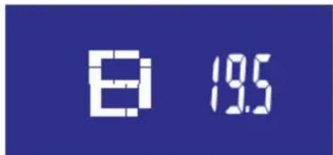
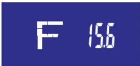
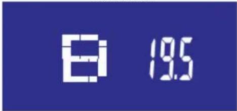
- LCD will display BMI (Drawing 32), FAT % (Drawing 33) and BODY FAT advice symbol (Drawing 34).
- Error message:
*The LCD displays “----” ““ ----”—means not hand the grip correctly.
*E-1—There is no heart rate signal input detected.
*E-4—Occurs when FAT% and BMI result is below 5 or exceeds 50.
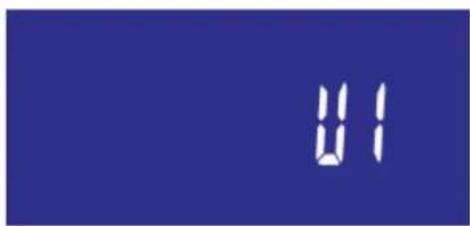
Drawing 28
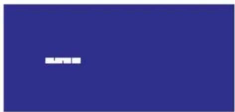
natural_image
Solid blue background with a small white rectangular shape in the top right corner (no text or symbols)Drawing 29

natural_image
Solid blue background with a single white horizontal line in the center (no text or symbols)Drawing 30
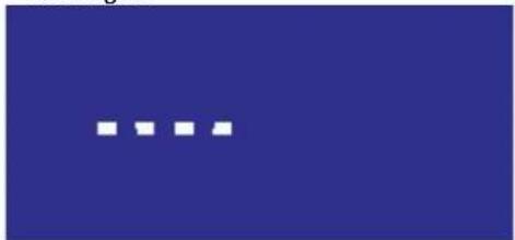
natural_image
Solid blue background with three white square dots in the bottom row (no text or symbols)Drawing 31
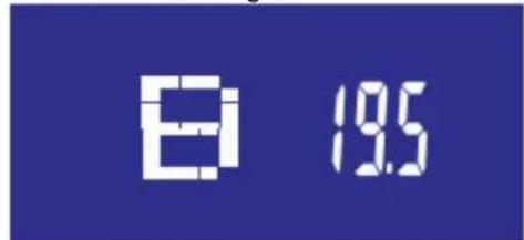
Drawing 32
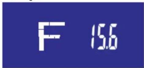
Drawing 33
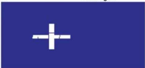
natural_image
Blue background with a white plus sign in the center (no text or symbols)Drawing 34
iConsole ^+ APP
User can connect console to tablet for APP function through two methods:
- Plugin audio cable into Tunelinc hole to connect the console to tablet. Turn on iconsole+app on tablet, and start workout with tablet.
- Plug Bluetooth module with USB key to the console. Turn on Bluetooth on tablet, search for console device and press connect. (password: 0000)
Turn on iconsole+ app on tablet and start workout with tablet.



USB power charger
The console provides USB power charger for tablet and smart phone only.
iConsole+
Android - system requirements
1280*800 Android 4.0 or above
Support devices:
Samsung Galaxy 10.1, Samsung Galaxy Tab2 Samsung Galaxy Tab3, Asus MeMo Pad 10, Asus Tf101
iOS - system requirements
iOS 5.1.1 or above
Support devices:
iPad4, iPad3, iPad2, iPad mini, iPad Air. iPhone4s, iPhone5, iPhone5s, iPhone6




Quick Start Guide
Step 1.
Download app




Step 3.
Open app
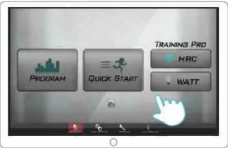
Step 5.
Workout summary
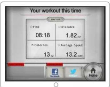
Step 2.
Connect your device with 3,5 mm Audio cable or Bluetooth
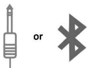
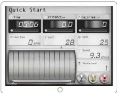
Step 4.
Start workout
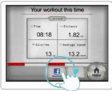
Step 6.
Share on Facebook or Twitter
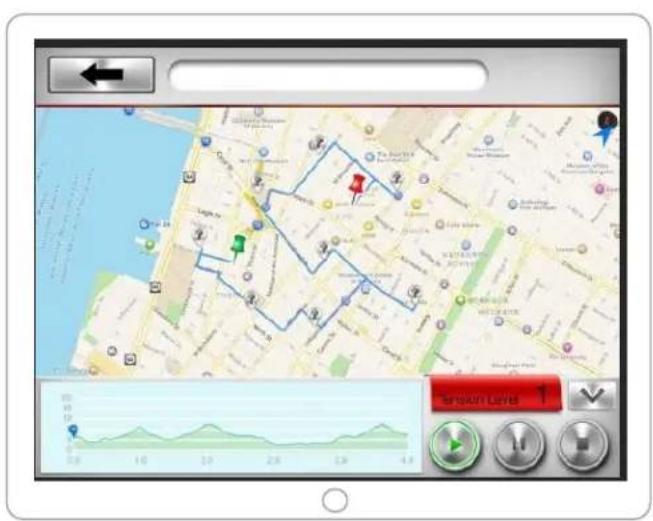
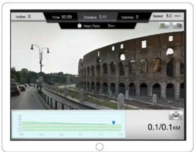
Plan your own route on map
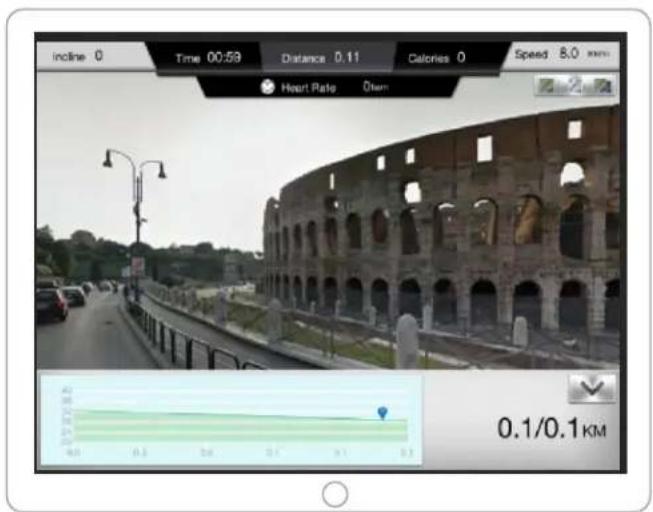
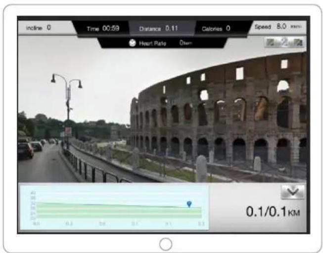
Exercise with Google Street View
Download Complete User Guide: http://manual.abisal.pl/iConsole.pdf
Training instruction
1. Warm-Up
To prevent injury and maximize performance we recommend that each workout period starts with a warm-up. We suggest you do the following exercise as the sketch map. Each exercise at least about 30 seconds.
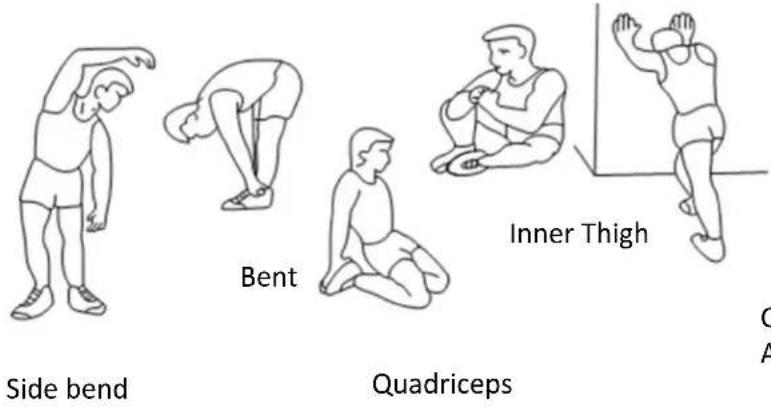
Calf and Achilles
2. Position
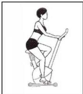
Seat down at the saddle, put feet's in to pedals, hands put on the handlebar. Keep your back straight.
natural_image
Line drawing of a person performing a stationary exercise on a scooter (no text or symbols)3. Training Organization
Warm-up:
Before every training you should warm-up for 5-10 minutes. Here you can do some stretching and training with low resistance.
Training session:
During the actual training a rate of 70% - 85% of the maximum pulse rate should be chosen. The time-length of your training session can be calculated with the following rule of thumb:
- daily training session: approx. 10 min. per unit
- 2-3 x per week: approx. 30 min. per unit
- 1-2 x per week: approx. 60 min. per unit
Cool down:
To introduce an effective cool-down of the muscles and the metabolism the intensity should be drastically decreased during the last 5 – 10 minutes. Stretching is also helpful for the prevention of muscle aches.
Success
Even after a short period of regular exercises you will notice that you constantly have to increase the resistance to reach your optimum pulse rate. The units will be continuously easier and you will feel a lot fitter during your normal day. For this achievement you should motivate yourself to exercise regularly.
Choose fixed hours for your training session and do not start training too aggressively. Even though we go to great efforts to ensure the quality of each product we produce, occasional errors and/or omissions do occur. In any event should you find this product to has either a defective or a missing part. Please contact us for a replacement.
Terms of references
Stationary bike exercises are replacing bicycle exercises. Magnetic bike M0410 is item class H. Unit is not intended for commercial use therapy or rehabilitation.
WARNING Heart rate monitoring systems may be inaccurate. Over exercising may result in serious injury or death. If you feel faint stop exercising immediately.
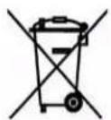
The equipment label depicting a crossed-out wheeled bin symbol informs that it is forbidden to dispose of waste electrical and electronic equipment together with other types of waste. In accordance with the WEE directive on waste electrical and electronic equipment, separate waste management processes should be applied for this type of equipment. The user who intends to dispose of such a product is obliged to return it to an electronic equipment collection point thanks to which they can contribute to its re-use, recycling,
and recovery and, in this way, protect the environment. To do this, contact the sales point where the equipment was purchased or a representative of the local authorities. Hazardous substances included in electronic equipment can have negative long-term influence on the natural environment and they can also have negative effect on human health.

Consumer service department:
ABISAL Sp. z o.o.
ul. Św. Elżbiety 6
41–905 Bytom
abisal@abisal.pl
www.abisal.pl
www.hms-fitness.pl
Bezpečnostní pokyny
Seznam částí
Funkce displeje
Obrázek 1
Obrázek 2
Obrázek 3
Obrázek 4
Volba tréninku
bar
| Category | Value | |---|---| | Speed | 0.0 | | Time | 0.0 | | Distance | 0.0 | | Calories | 0 | | Pulse | 1 |Obrázek 16
Režim H.R.C.
Obrázek 20
natural_image
Solid blue background with a small white rectangular shape in the center (no text or symbols)Obrázek 29
natural_image
Solid blue background with a single white horizontal line in the center (no text or symbols)Obrázek 30
natural_image
Solid blue background with three white squares in the bottom row (no text or symbols)Obrázek 31
Obrázek 32
Obrázek 33

natural_image
Blue background with a white plus sign in the center (no text or symbols)Obrázek 34
iConsole+
Krok 6.
Cvičte s Google Street View
Návod k tréninku
1. Rozcvička
natural_image
Line drawing of a person performing a stationary exercise on a stationary bike (no text or symbols)4. Plán tréninku


- UWAGI DOTYCZĄCE BEZPIECZEŃSTWA
- Diagram montażowy
- Instrukcja montażu
- Przygotowanie
- Wybór programu
- iConsole+
- Krok 2.
- Krok 6.
- Instrukcja treningu
- Rozgrzewka
- IMPORTANT SAFETY INFORMATION
- WARNING: READ ALL INSTRUCTIONS BEFORE USING ANY FITNESS EQUIPMENT. WE ASSUME NO RESPONSIBILITY FOR PERSONAL INJURY OR PROPERTY DAMAGE CAUSED BY OR THROUGH THE USE OF THIS PRODUCT
- SPECIFICATIONS
- MAINTENANCE
- BREAKING
- TENSION ADJUSTMENT
- Exploded View
- Assembly Diagram
- Assembly:
- Preparation
- Assembly process
- STEP 1. Front stabilizer and rear stabilizer
- STEP 2. Pedals
- STEP 3. Computer post
- STEP 4. Handle bar
- STEP 5. Computer
- STEP 6. Seat
- Computer
- Operation procedure
- POWER ON
- WORKOUT SELECTION
- Manual Mode
- Program Mode
- H.R.C Mode
- Watt Mode
- User Program Mode
- Recovery
- Body fat
- iConsole + APP
- USB power charger
- Quick Start Guide
- Step 1.
- Step 3.
- Step 5.
- Step 2.
- Step 4.
- Step 6.
- Training instruction
- Warm-Up
- Position
- Training Organization
- Success
- Terms of references
- Bezpečnostní pokyny
- Volba tréninku
- Režim H.R.C.
- Návod k tréninku
- Rozcvička
- Plán tréninku
Brand : HMS Premium
Model : M0410
Category : Home trainer