Solplanet ASW100K-LT - Solar panel

ASW100K-LT - Solar panel Solplanet - Free user manual and instructions

Find the device manual for free ASW100K-LT Solplanet in PDF.

📄 102 pages English EN Download 💬 AI Question 10 questions ⚙️ Specs
Notice Solplanet ASW100K-LT - page 3
Pick your language and provide your email: we'll send you a specifically translated version.
Product Type Grid-Tie Photovoltaic Inverter
Brand Solplanet
Model ASW100K-LT
Phase Three-phase
Transformerless Yes
Max DC Input Voltage 1100 V (typical)
Number of MPPT Trackers 4
Max AC Output Power 100 kW
Communication RS485, WiFi (optional stick), LAN, 4G
Protection Class IP65 (indoor/outdoor use)
Operating Temperature Range -25°C to +60°C (typical)
Cooling Forced air cooling
Safety Features Ground fault monitoring, overvoltage protection, capacitor discharge warning
Certifications CE (EU Declaration of Conformity)
Display None (setup via mobile app or web interface)
Mounting Wall-mounted (bracket included)
PV Module Compatibility Class II, capacitance ≤5 μF
DC Input Connectors 20 inputs (Phoenix Contact type)
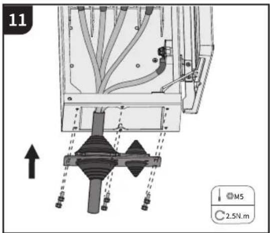
AC Connection Knockout seal for AC cable
Residual Current Monitoring Integrated

Frequently Asked Questions - ASW100K-LT Solplanet

What is the maximum DC input voltage of the Solplanet ASW100K-LT?
The maximum DC input voltage is typically 1100 V, but always refer to the datasheet for exact specifications.
How many MPPT trackers does the ASW100K-LT have?
The inverter features 4 MPPT trackers, each connected to a set of DC inputs (DC switches 1-4).
Is the Solplanet ASW100K-LT suitable for outdoor installation?
Yes, it is designed for both indoor and outdoor use with a protection class of IP65 (typical).
What communication options are available?
The inverter supports RS485 and optional WiFi, LAN, or 4G communication via an external stick.
Does the ASW100K-LT have a transformer?
No, it is a transformerless inverter, so it does not provide galvanic isolation.
How should the AC cable be connected?
The AC cable is connected via a knockout seal on the inverter. Detailed steps are provided in the installation guide.
What type of PV modules are compatible?
Only PV modules of protection class II (IEC 61730, application class A) with capacitance to ground ≤5 μF are allowed.
What safety precautions are necessary before installation?
Always disconnect the inverter from all voltage sources and wait 25 minutes for capacitor discharge. Use proper PPE and follow the manual.
How do I set up WiFi communication?
Insert the optional WiFi stick into the dedicated port, then use the Solplanet mobile app to configure network settings.
Where can I find the full user manual?
The full manual and quick installation guide are available in PDF format at www.solplanet.net.

User questions about ASW100K-LT Solplanet

0 question about this device. Answer the ones you know or ask your own.

Ask a new question about this device

The email remains private: it is only used to notify you if someone responds to your question.

No questions yet. Be the first to ask one.

Download the instructions for your Solar panel in PDF format for free! Find your manual ASW100K-LT - Solplanet and take your electronic device back in hand. On this page are published all the documents necessary for the use of your device. ASW100K-LT by Solplanet.

USER MANUAL ASW100K-LT Solplanet

Quick Installation Guide

ASW75K-LT/ASW80K-LT/ASW100K-LT/ASW110K-LT

QR code with a central purple logo, likely linking to a digital resource or website.

Android

QR code with a central logo, likely linking to a digital resource or website.

iOS

TABLE OF CONTENTS

English

Quick Installation Guide....1

Deutsche

This quick installation guide does not replace the description in the user manual.

The contents of this guide may be updated or revised due to product development. The information in this guide is subject to change without notice. The latest version of this document and the manual for installation, commissioning, configuration and decommissioning are to be found in PDF format at www.solplanet.net.

2 SAFETY

2.1 Intended use

The product is a transformerless PV inverter which converts the direct current of the PV generator into grid-compatible three-phase alternating current and then feeds the three-phase alternating current into the public power grid.

The product is intended for indoor and outdoor applications.

The product must only be connected with PV modules of protection class II (in accordance with IEC 61730, application class A). PV modules with a high capacitance to ground must only be used if their capacity does not exceed 5μF. Do not connect any sources of energy other than PV modules to the product.

The product is not equipped with an integrated transformer and therefore has no galvanic isolation. The product must not be operated with PV modules which require functional grounding of either the positive or negative PV conductors. This can cause the product to be irreparably damaged. The product may be operated with PV modules with frames that require protective earthing.

All components must remain within their permitted operating ranges and their installation requirements at all times.

Use the product only in accordance with the information provided in the user manual and with the locally applicable standards and directives. Any other application may cause personal injury or damage to property.

The product must only be used in countries for which it is approved by AISWEI and the grid operator.

The type label must be permanently attached to the product and must be in a legible condition.

This document does not replace any regional, state, provincial, federal or national laws, regulations or standards that apply to the installation, electrical safety and use of the product.

2.2 Important safety instructions

The product has been designed and tested strictly according to the international safety requirements. As with all electrical or electronic devices, there are residual risks despite careful construction. To prevent personal injury and property damage and to ensure long-term operation of the product, read this section carefully and observe all safety information at all times.

Solplanet ASW100K-LT - Important safety instructions - 1

DANGER

Danger to life due to high voltages of the PV array!

When exposed to sunlight, the PV array generates dangerous DC voltage which is present in the DC conductors and the live components of the product. Touching the DC conductors or the live components can cause to lethal electric shocks. If you disconnect the DC connectors from the product under load, an electric arc may occur leading to electric shock and burns.

  • Do not touch non-insulated cable ends.
  • Do not touch the DC conductors.
  • Do not touch any live components of the product.
  • Do not open the product.
  • All work on the product must only be carried out by qualified personnel who have read and fully understood all safety information contained in this document and the user manual.
  • Disconnect the product from voltage and energy sources and ensure it cannot be reconnected before working on the product.
  • Wear suitable personal protective equipment for all work on the product.

Solplanet ASW100K-LT - DANGER - 1

DANGER

Danger to life due to electric shock when touching live system components in case of a ground fault!

If a ground fault occurs, parts of the system may still be live. Touching live parts and cables may result in death or lethal injuries due to electric shock.

  • Disconnect the product from voltage and energy sources and ensure it cannot be reconnected before working on the device.
  • Only touch the cables of the PV modules on their insulation.
  • Do not touch any parts of the substructure or frame of the PV array.
  • Do not connect PV strings with ground faults to the product.

Solplanet ASW100K-LT - DANGER - 1

WARNING

Danger to life due to electric shock from destruction of the measuring device due to overvoltage!

Overvoltage can damage a measuring device and result in voltage being present in the enclosure of the measuring device. Touching the live enclosure of the measuring device results in death or lethal injuries due to electric shock.

- Only use measuring devices with the measurement span higher than the DC input voltage range equal to or higher than the voltage rating of the product.

Solplanet ASW100K-LT - WARNING - 1

CAUTION

Risk of burns due to high temperature.

Some parts of the enclosure can become hot during operation.

- During operation, do not touch any parts other than the enclosure lid of the product.

Solplanet ASW100K-LT - CAUTION - 1

CAUTION

Risk of injury due to weight of product.

Injuries may result if the product is lifted incorrectly or dropped while being transported or mounted.

- Transport and lift the product carefully. Take the weight of the product into account.

- Wear suitable personal protective equipment for all work on the product.

2.3 Symbols on the label

Solplanet ASW100K-LT - Symbols on the label - 1Beware of a danger zoneThis symbol indicates that the inverter must be additionally grounded if additional grounding or equipotential bonding is required at the installation site.
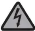
Solplanet ASW100K-LT - Symbols on the label - 2Beware of high voltage and operating currentThe inverter operates at high voltage and current. Work on the inverter must only be carried out by skilled and authorized electricians.
Solplanet ASW100K-LT - Symbols on the label - 3Beware of hot surfacesThe inverter may become hot during operation. Avoid contact during operation.
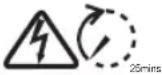
Solplanet ASW100K-LT - Symbols on the label - 4Capacitor dischargeDanger to life due to high voltages in the inverter. Do not touch live parts for 25 minutes after disconnection from the power sources.
Solplanet ASW100K-LT - Symbols on the label - 5Observe the documentationObserve all documentation supplied with the product.

3 EU DECLARATION OF CONFORMITY

Within the scope of the EU directives

• Radio Equipment Directive 2014/53/EU

(L 153/62-106. May 22. 2014) (RED)

- Restriction of the use of certain hazardous substances 2011/65/EU

(L 174/88, June 8, 2011) and 2015/863/EU (L 137/10, March 31, 2015) (RoHS)

confirms herewith that the products described in this document are in compliance with the fundamental requirements and other relevant provisions of the above mentioned directives. The entire EU Declaration of Conformity can be found at www.sol-planet.net.

Solplanet ASW100K-LT - EU DECLARATION OF CONFORMITY - 1

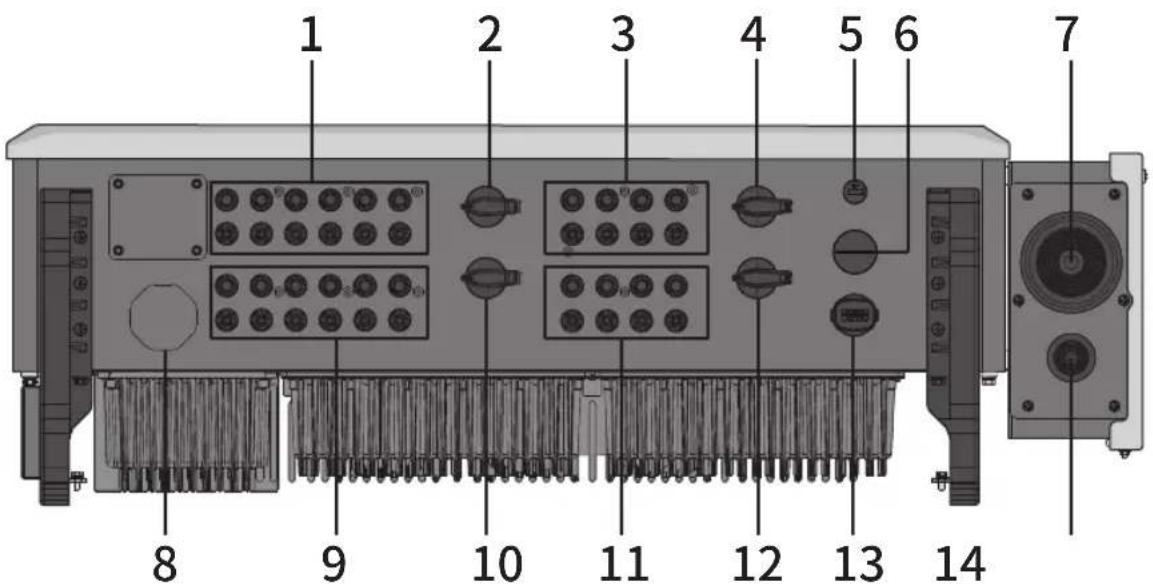
4 OVERVIEW

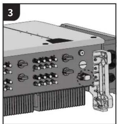
1 2 3 4 5 6 7 8 9 10 11 12 13 14

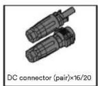
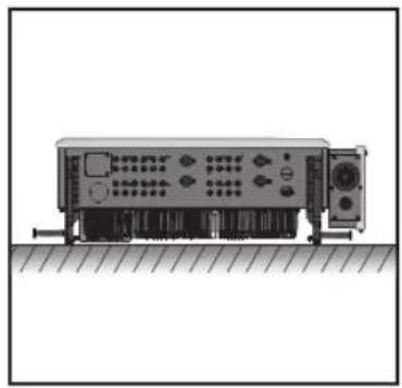
1 DC connector inputs 1-6 (connected to DC switch 1)

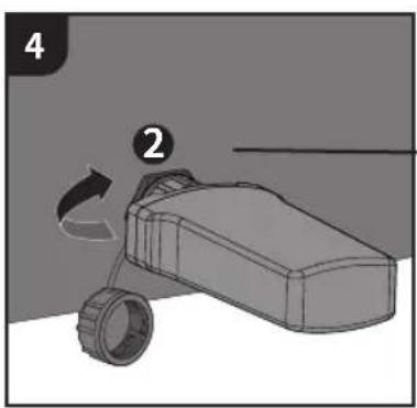
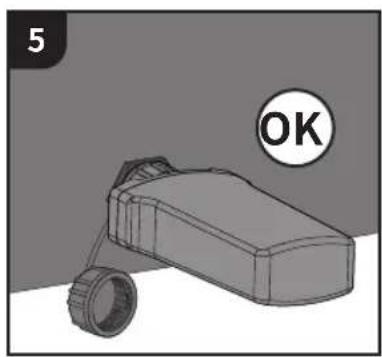
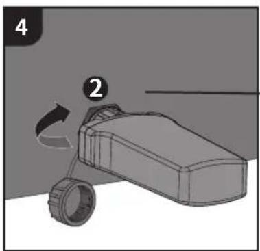
8 Lock valve

2 DC switch 1

9 DC connector inputs 7-12 (Connected to DC switch 2)

3 DC connector inputs 13-16 (connected to DC switch 3)

10 DC switch 2

4 DC switch 3

11 DC connector inputs 17-20 (Connected to DC switch 4)

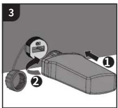
5 WiFi stick port

12 DC switch 4

6 Reserved terminal

13 RS485 Communication port

7 AC cable - knockout seal

14 Reserved grounding - knockout seal

5 SCOPE OF DELIVERY

Diagram of an Inverter x1 device with mounting feet and internal components (no text or symbols on the device itself)

Solplanet ASW100K-LT - SCOPE OF DELIVERY - 2

Solplanet ASW100K-LT - SCOPE OF DELIVERY - 3

Solplanet ASW100K-LT - SCOPE OF DELIVERY - 4

Solplanet ASW100K-LT - SCOPE OF DELIVERY - 5

Solplanet ASW100K-LT - SCOPE OF DELIVERY - 6

Solplanet ASW100K-LT - SCOPE OF DELIVERY - 7

Solplanet ASW100K-LT - SCOPE OF DELIVERY - 8

Solplanet ASW100K-LT - SCOPE OF DELIVERY - 9

Solplanet ASW100K-LT - SCOPE OF DELIVERY - 10

Solplanet ASW100K-LT - SCOPE OF DELIVERY - 11

Solplanet ASW100K-LT - SCOPE OF DELIVERY - 12

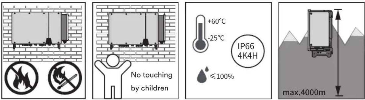
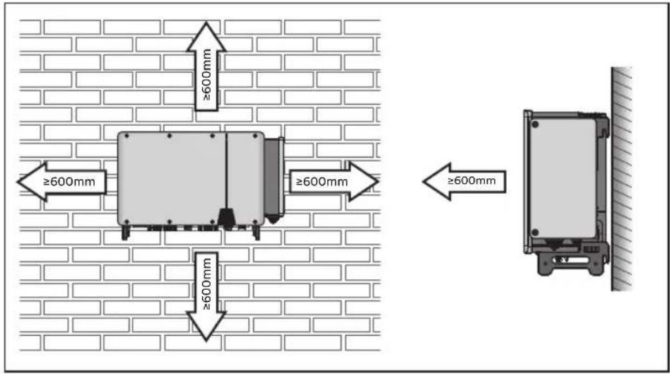
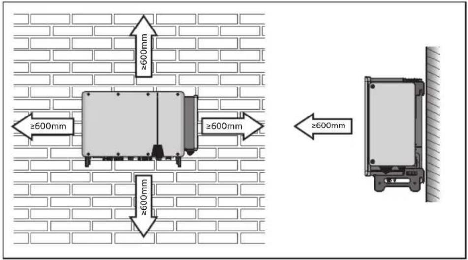
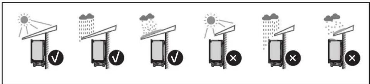
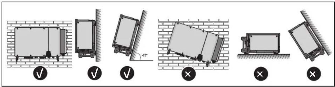
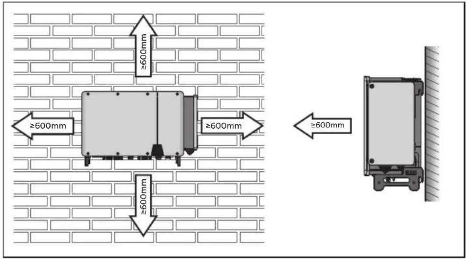
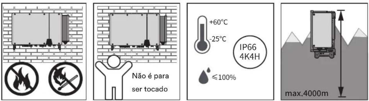
MOUNTING ENVIRONMENT

Diagram showing six scenarios of weathering and rain protection with checkmarks and crosses indicating failure or rejection conditions.

Diagram illustrating six different installation or mounting methods with check and cross symbols, including angle annotations like >75°.

No touching by children +60°C -25°C IP66 4K4H ≤100% max.4000m

Solplanet ASW100K-LT - MOUNTING ENVIRONMENT - 4

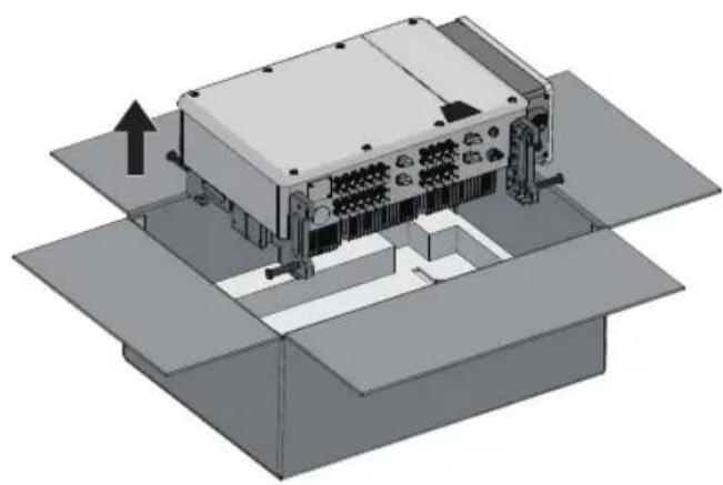
8.1 Take out the inverter

Technical illustration of an electronic device with internal components and mounting brackets (no text or symbols)

8.2 Moving the inverter (Optional)

Pure technical diagram of a rectangular device with mounting flanges and internal components (no text or symbols)

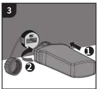
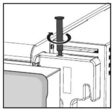
Technical line drawing of a mechanical assembly with a cylindrical component inserted into a housing (no text or symbols)

Illustration of a multi-chamber electronic device mounted on a surface, no visible text or symbols

Diagram of a mechanical lifting device with a crane hook and base components (no text or symbols)

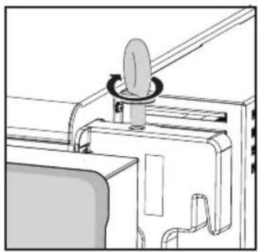
Technical line drawing of a mechanical device with a knob and rotating knob (no text or symbols)

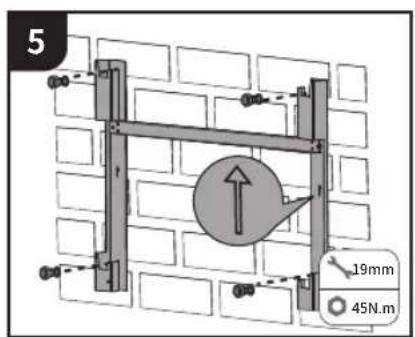
8.3 Mounting-bracket

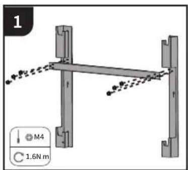
1 M4 C 1.6N m

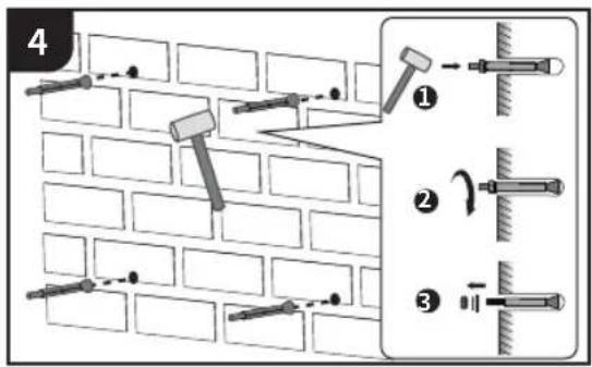
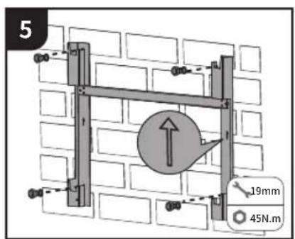
Diagram of a metal fence structure mounted on a brick wall, with no visible text or symbols

3 4-Φ12 90° 65mm

4 ① ② ③

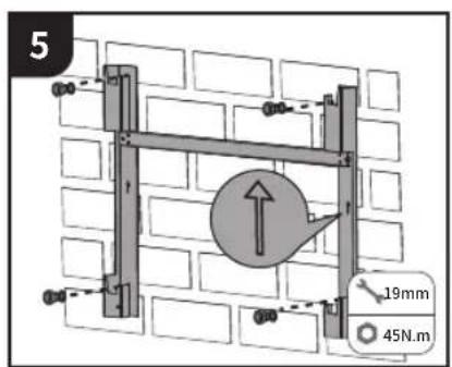
5 19mm 45N.m

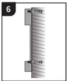
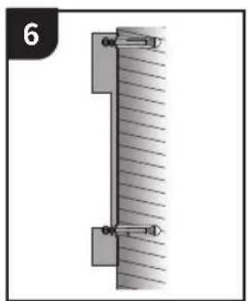
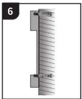
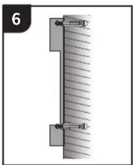
Pure mechanical diagram showing a vertical beam with hatched fill and two circular fasteners, no text or symbols present.

8.4 Wall-Mounted Installation

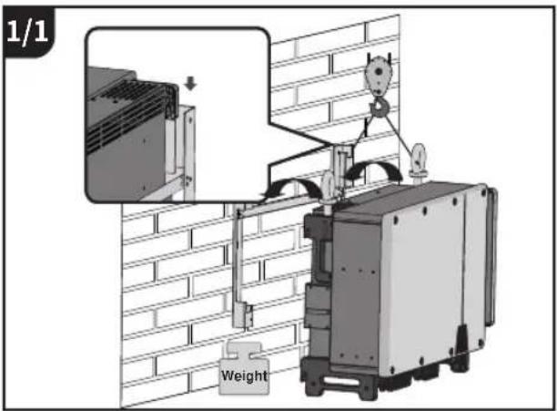
1/1 Weight

1/2 Weight

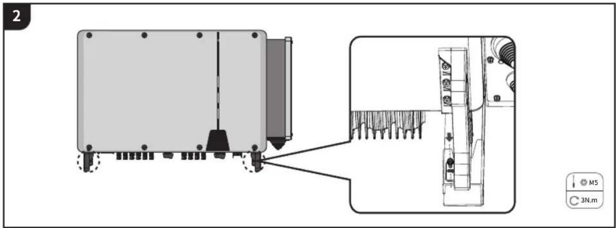
2 M5 3N.m

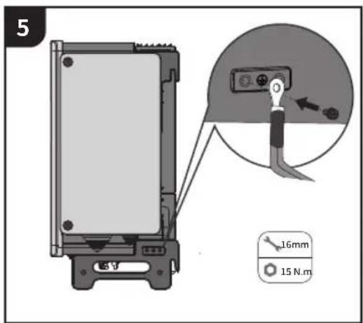
9 SECOND PROTECTIVE GROUNDING

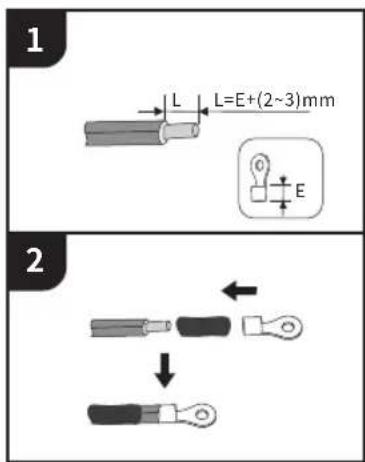
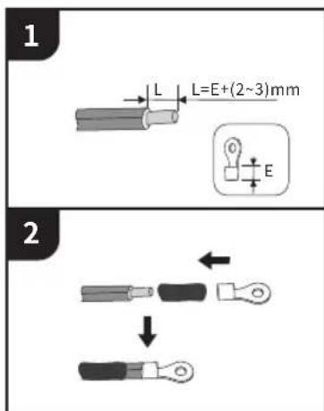
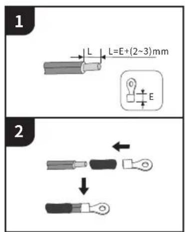
1 L L=E+(2~3)mm E 2

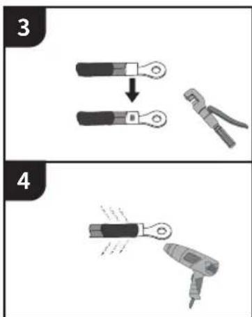
Diagram showing two-step tool manipulation: step 3 shows a wire being cut, step 4 shows a drill using a power tool.

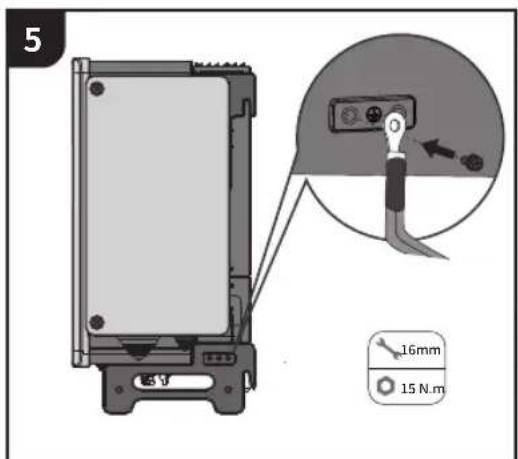
5 16mm 15 N.m

10

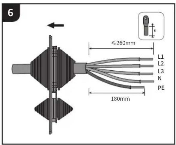
AC CONNECTION

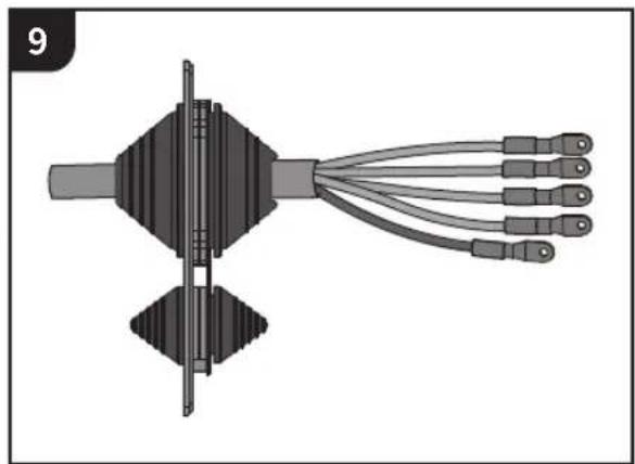
Technical diagram showing assembly steps of a device with labeled components and directional arrows

2 OFF

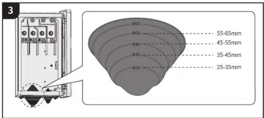
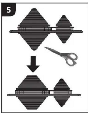
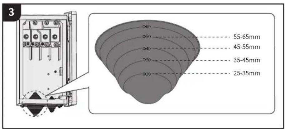
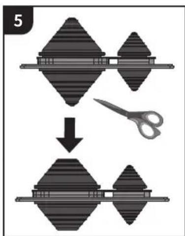
3 Φ60 Φ50 Φ40 Φ30 Φ20 55-65mm 45-55mm 35-45mm 25-35mm

4 MS

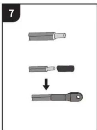
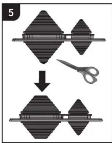
5

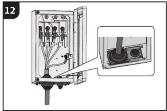
6 ≤260mm L1 L2 L3 N PE 180mm

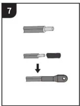
7

8

Diagram of a mechanical or electrical connector with multiple wires and a central shaft (no text or symbols)

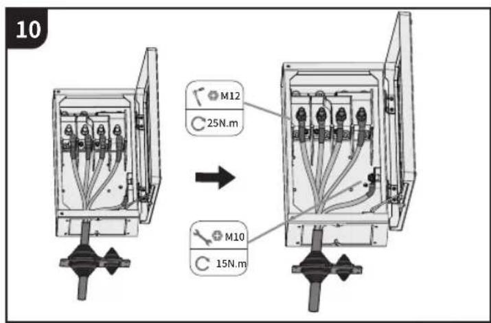
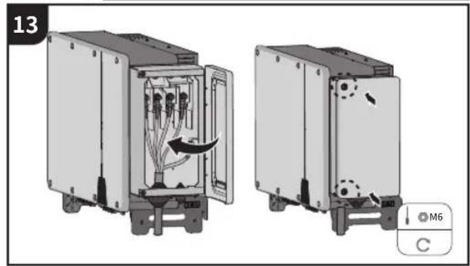
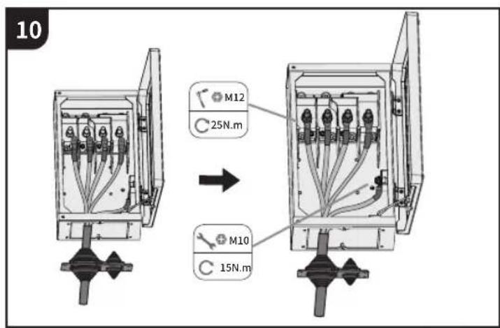
10 M12 25N.m M10 15N.m

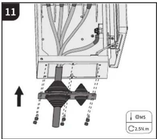
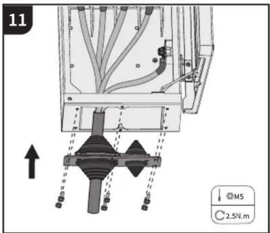
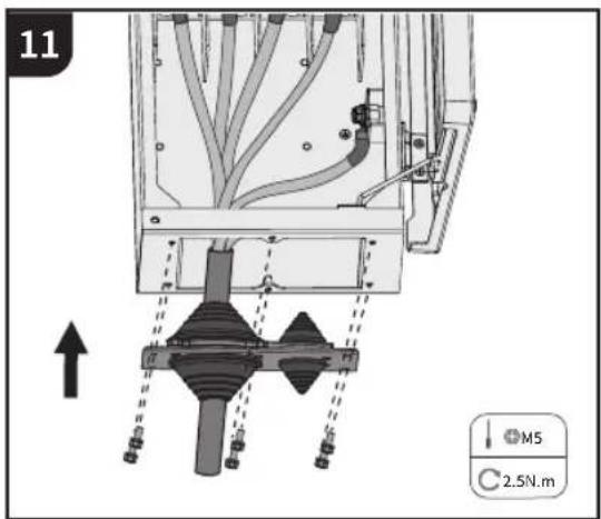
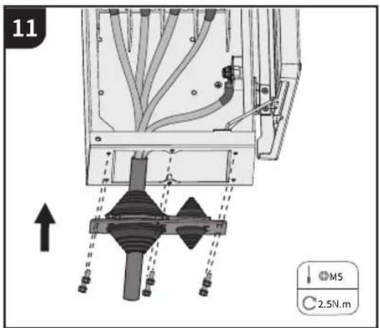
11 M5 2.5N.m

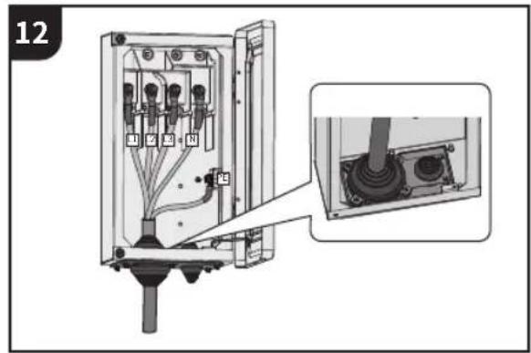
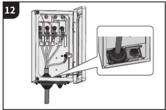
12 1 2 3 4 5 6 7 8 9 10 11 12 13 14 15 16 17 18 19 20 21 22 23 24 25 26 27 28 29 30 31 32 33 34 35 36 37 38 39 40 41 42 43 44 45 46 47 48 49 50 51 52 53 54 55 56 57 58 59 60 61 62 63 64 65 66 67 68 69 70 71 72 73 74 75 76 77 78 79 80 81 82 83 84 85 86 87 88 89 90 91 92 93 94 95 96 97 98 99 10

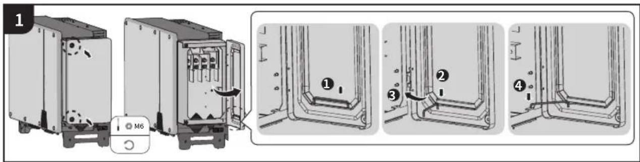
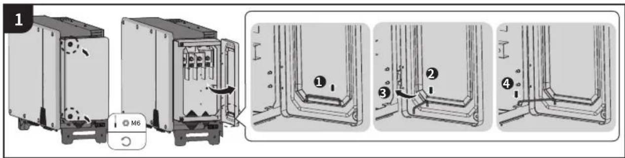
13 M6 C

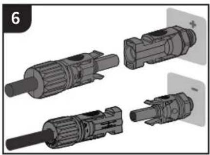
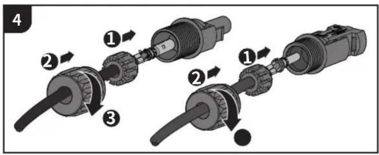
11 DC CONNECTION

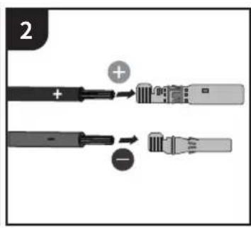
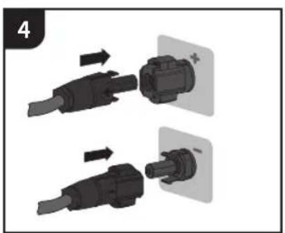
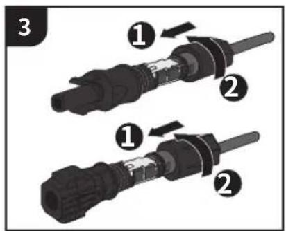
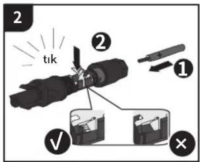
TYPE 1 - Phoenix Contact
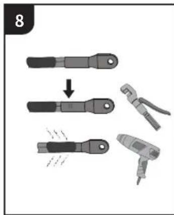
1 2.5-6mm² ≥7 12mm Φ -5 8mm

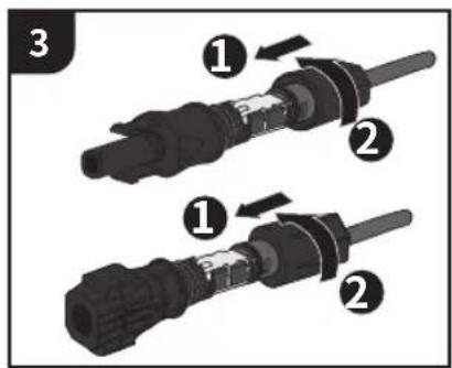
2 click ② ① ✓ ×

Diagram showing two connected electrical connectors with numbered parts and directional arrows indicating assembly or movement.

Two-step diagram showing cable installation of a plug into a socket, with no text or symbols present.

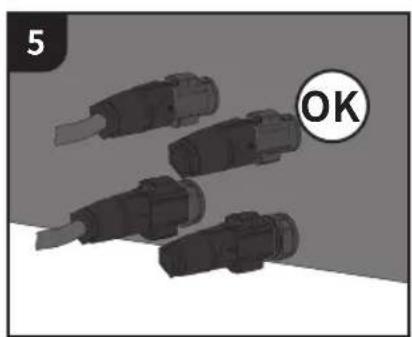
Illustration of four black USB connectors with a circular 'OK' label, no text or symbols present

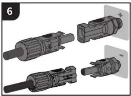
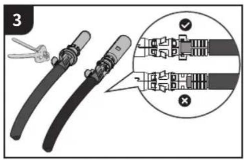
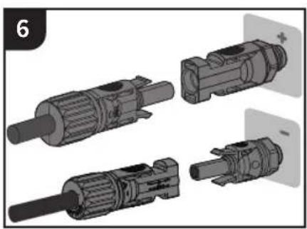
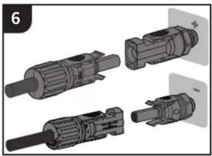
TYPE 2

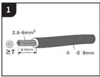
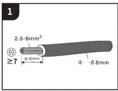
1 2.5-6mm² ≥7 8-10mm Φ -5 8mm

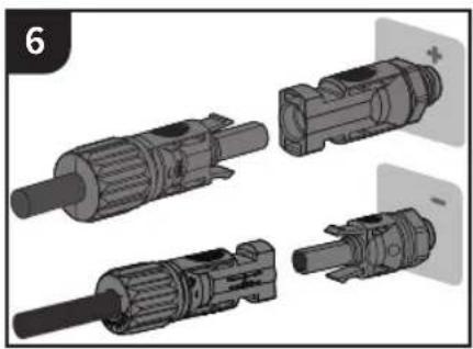
2 + + -

3

Diagram showing three-step assembly of a mechanical connector with numbered parts, likely illustrating a mechanical or electrical component assembly.

Illustration of mechanical tools including a flat tool and a cylindrical component (no text or symbols)

Exploded view diagram of four mechanical components (no text or symbols)

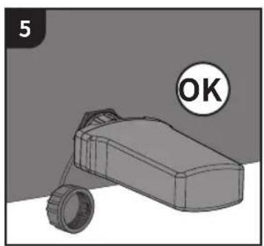
Illustration of multiple cylindrical mechanical components with a circular 'OK' badge (no text or symbols on components)

12

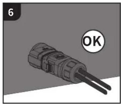
COMMUNICATION SETUP

12.1 RS485 cable connection

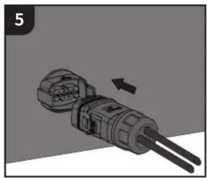
Pin 1=Power+ Pin 2=GND Pin 3=485A Pin 4=485B Pin 5=Power+ Pin 6=GND Pin 7=485A Pin 8=485B

2 ① ② ③ ④ ⑤ C 1.2±0.1N.m

Diagram of an electronic device showing ports and connectors (no text or symbols visible)

Two mechanical devices with a directional arrow indicating movement or change (no text or symbols present)

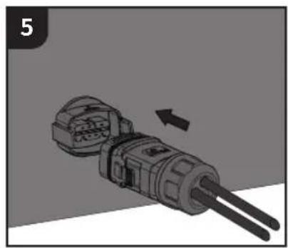
3D illustration of a mechanical component with two rods and a directional arrow (no text or symbols)

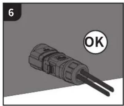
Close-up of a mechanical component with two leads, labeled 'OK' (no text or symbols on the object itself)

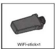
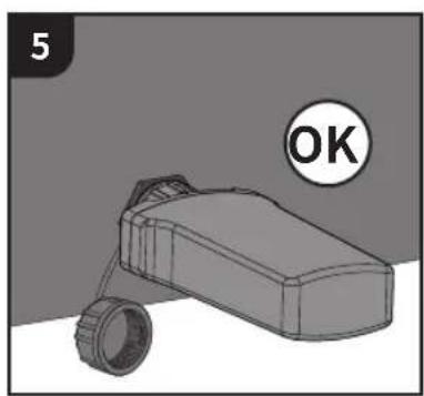
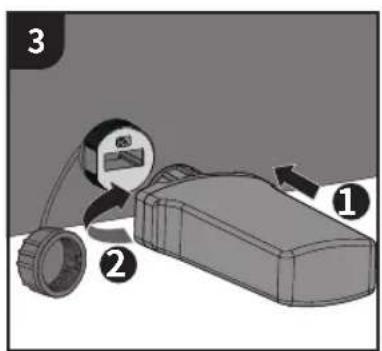
12.2 WiFi/LAN/4G stick connection

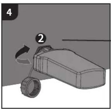
Close-up of a mechanical or electronic component with multiple ports and connectors, no visible text or symbols

Diagram of a mechanical component with directional arrows indicating motion (no text or symbols)

Diagram showing a device with labeled parts and directional arrows, likely illustrating a process or installation.

Illustration of a toy car with wheels and a handle, showing motion direction (no text or symbols)

Illustration of a hand holding a device with a checkmark symbol (no text or labels present)

Illustration of a hand pressing a component with a cross symbol (no text or labels)

3D rendered object resembling a toy car with wheels, set against a plain background (no text or symbols)

13

CONTACT

Please contact our Service Department if you have any technical questions about our products.

The following information is needed to provide necessary assistance:

——Inverter model
——Inverter serial number
—Photovoltaic module model
—Photovoltaic modules number and strings number connected to each MPPT
——Fault code
——Installation location
——Warranty card

EMEA

Service email: service.EMEA@solplanet.net

APAC

Service email: service.APAC@solplanet.net

LATAM

Service email: service.LATAM@solplanet.net

Aiswei Greater China

Service email: service.china@aiswei-tech.com

Hotline: +86 400 801 9996

Taiwan

Service email: service.taiwan@aiswei-tech.com

Hotline: +886 809089212

https://solplanet.net/contact-us

Scan QR code:

QR code with a central logo, likely linking to a digital resource or website.

Android

Scan QR code:
QR code with a central logo, likely linking to a digital resource or website.

iOS

1 ALLGEMEINE INFORMATIONEN
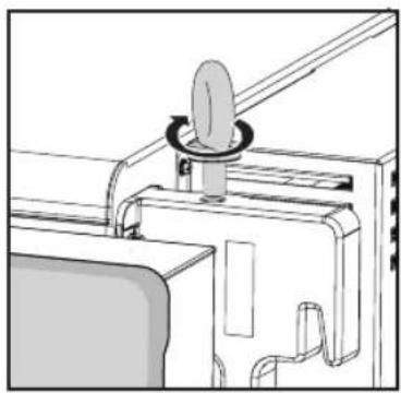
Diagram illustrating six different installation or mounting methods for a wall-mounted device, with check and cross icons indicating status.

Von Kindern fern halten +60°C -25°C IP66 4K4H ≤100% max.4000m

Cross-sectional diagram of a mechanical or structural component with arrows indicating force or movement (no text or symbols present)

3D technical illustration of an electronic device with internal components and a directional arrow (no text or symbols)

Technical line drawing of a mechanical assembly with a cylindrical component inserted into a housing (no text or symbols)

Illustration of a multi-chamber electronic device mounted on a surface, no visible text or symbols

Diagram of a crane lifting a rectangular device with a handle and base (no text or symbols)

Mechanical assembly diagram showing a rotating knob mounted on a bracket (no text or symbols)

3 4-Φ12 90° 65mm

4 ① ② ③

5 19mm 45N.m

Pure mechanical component diagram without any text, numbers, or symbols

8.4 Wandmontage

1 L L=E+(2~3)mm E 2

Diagram showing two-step tool application: step 3 of a wire clamp being added to a wire, and step 4 of a drill press being inserted.

5 16mm 15 N.m

10

2 OFF

3 Φ60 Φ50 Φ40 Φ30 Φ20 55-65mm 45-55mm 35-45mm 25-35mm

4 MS

5

6 ≤260mm L1 L2 L3 N PE 180mm

7

8

Diagram of a mechanical or electrical connector with multiple wires and a central shaft (no text or symbols)

10 M12 25N.m M10 15N.m

11 M5 C 2.5N.m

12 1 2 3 4 5 6 7 8 9 10 11 12 13 14 15 16 17 18 19 20 21 22 23 24 25 26 27 28 29 30 31 32 33 34 35 36 37 38 39 40 41 42 43 44 45 46 47 48 49 50 51 52 53 54 55 56 57 58 59 60 61 62 63 64 65 66 67 68 69 70 71 72 73 74 75 76 77 78 79 80 81 82 83 84 85 86 87 88 89 90 91 92 93 94 95 96 97 98 99 100

Two views of an electrical enclosure showing internal wiring and components, with no visible text or symbols.

Two-step diagram showing cable installation process with arrows indicating direction (no text or symbols)

Illustration of four black USB connectors with a circular 'OK' button, no text or symbols present

TYP 2

1 2.5-6mm² ≥7 8-10mm Φ -5 8mm

2 + + -

3

Diagram showing three-step assembly of a mechanical component with numbered parts and directional arrows indicating sequence.

Illustration of mechanical tools including a fork and plug assembly (no text or symbols)

Exploded view diagram of four mechanical components (no text or symbols)

Illustration of multiple cylindrical mechanical components with a circular badge labeled 'OK' (no text or symbols on the objects themselves)

12

KOMMUNIKATIONSAUFBAU

Two electronic devices with a directional arrow indicating movement or change (no text or symbols visible)

3D illustration of a mechanical connector with two tubes and a directional arrow (no text or symbols)

Close-up of a mechanical component with two wires, labeled 'OK' (no text or symbols on the object itself)

Diagram of a mechanical pulley system with directional arrows indicating motion (no text or labels)

Diagram showing a device with labeled parts and directional arrows, likely illustrating a process or installation.

3D diagram of a mechanical device with labeled parts (no text or symbols present)

Illustration of a hand pressing down on a mechanical component with a checkmark (no text or symbols)

Illustration of a hand pressing a button on a device (no text or symbols visible)

3D rendered object resembling a vehicle or device with a circular button labeled 'OK' (no text or symbols on the object itself)

13

KONTAKT

https://solplanet.net/contact-us

QR-Code

QR code with a central logo, likely linking to a digital resource or website.

Android

QR-Code
QR code with a central logo, likely linking to a digital resource or website.

iOS

1 ALGEMENE INFORMATIE

Solplanet ASW100K-LT - ALGEMENE INFORMATIE - 1

Solplanet ASW100K-LT - ALGEMENE INFORMATIE - 2

Solplanet ASW100K-LT - ALGEMENE INFORMATIE - 3

Solplanet ASW100K-LT - ALGEMENE INFORMATIE - 4

Solplanet ASW100K-LT - ALGEMENE INFORMATIE - 5

Solplanet ASW100K-LT - ALGEMENE INFORMATIE - 6

Solplanet ASW100K-LT - ALGEMENE INFORMATIE - 7

Solplanet ASW100K-LT - ALGEMENE INFORMATIE - 8

Solplanet ASW100K-LT - ALGEMENE INFORMATIE - 9

Solplanet ASW100K-LT - ALGEMENE INFORMATIE - 10

Solplanet ASW100K-LT - ALGEMENE INFORMATIE - 11

6
MONTAGE-OMGEVING
Diagram showing six scenarios of weathering and rain protection with checkmarks and crosses indicating failure or rejection conditions.

Diagram illustrating six different installation or mounting methods for a wall-mounted device, with check and cross icons indicating status.

Cross-sectional diagram of a mechanical or structural component with directional arrows indicating force or movement (no text or symbols present)

3D technical illustration of an electronic device with a box and internal components, no visible text or symbols

Technical line drawing of a mechanical assembly with a bolt and bracket (no text or symbols)

Front view of a mechanical or electronic device with ports and connectors, mounted on a surface (no visible text or symbols)

Diagram of a mechanical lifting device with a crane hook and base (no text or symbols)

Mechanical assembly diagram showing a rotating knob and housing component (no text or symbols)

8.3 Montagebeugel

1 M4 C 1.6N.m

Diagram of a fence structure mounted on a brick wall, showing vertical supports and diagonal bracing (no text or symbols)

3 4-Φ12 90° 65mm

4 ① ② ③

5 19mm 45N.m

Pure mechanical diagram showing a vertical beam with hatched fill and two circular fasteners, no text or symbols present.

8.4 Wandmontage installatie

1 L L=E+(2~3)mm E 2

Diagram showing two-step tool manipulation: step 3 shows a wire being cut, step 4 shows a tool being inserted with motion arrows.

5 16mm 15 N.m

10

AC-VERBINDING

Technical diagram showing assembly steps of a mechanical device with labeled components and directional arrows

2 OFF

3 Φ60 Φ50 Φ40 Φ30 Φ20 55-65mm 45-55mm 35-45mm 25-35mm

4 MS

5

6 ≤260mm L1 L2 L3 N PE 180mm

7

8

Diagram of a mechanical or electrical connector with multiple wires and a central shaft (no text or symbols)

10 M12 25N.m M10 15N.m

11 M5 C 2.5N.m

12 1 2 3 4 5 6 7 8 9 10 11 12 13 14 15 16 17 18 19 20 21 22 23 24 25 26 27 28 29 30 31 32 33 34 35 36 37 38 39 40 41 42 43 44 45 46 47 48 49 50 51 52 53 54 55 56 57 58 59 60 61 62 63 64 65 66 67 68 69 70 71 72 73 74 75 76 77 78 79 80 81 82 83 84 85 86 87 88 89 90 91 92 93 94 95 96 97 98 99 100

13 M6 C

11 DC-VERBINDING

TYPE 1 Phoenix-contact
1 2.5-6mm² ≥7 ≈ 12mm Φ -5 8mm

2 klikken ② ① V ×

Diagram showing two connected electrical connectors with numbered parts and directional arrows indicating assembly or movement.

Two-step diagram showing cable installation process with arrows indicating direction (no text or symbols)

Illustration of four black industrial connectors with a circular 'OK' label, no text or symbols present

TYPE 2

1 2.5-6mm² ≥7 8-10mm Φ -5 8mm

2 + + -

3

Diagram showing three-step assembly of a mechanical connector with numbered parts and directional arrows indicating motion.

Technical illustration of a mechanical tool with two views (top and side), no text or symbols present

Exploded view diagram of four mechanical components (no text or symbols)

Illustration of multiple cylindrical mechanical components with a circular badge labeled 'OK' (no text or symbols on the objects themselves)

12

COMMUNICATIE INSTELLING

12.1 RS485 Kabelverbinding

1 Pin 1=Power+ Pin 2=GND Pin 3=485A Pin 4=485B Pin 5=Power+ Pin 6=GND Pin 7=485A Pin 8=485B

2 ① ② ③ ④ ⑤ C 1.2±0.1N.m

Diagram of an electronic device showing ports and connectors (no text or symbols visible)

Two mechanical devices with a directional arrow indicating movement or change (no text or symbols present)

3D illustration of a mechanical connector with two tubes and a directional arrow (no text or symbols)

Close-up of a mechanical connector with two leads, labeled 'OK' (no text or symbols on the component itself)

12.2 WiFi/LAN/4G stick-verbinding

Close-up of an electronic device rear panel with connectors and a mechanical component inserted (no visible text or symbols)

Diagram of a mechanical component with directional arrows indicating motion (no text or symbols)

Diagram showing a device with labeled parts and directional arrows, likely illustrating a process or installation.

Diagram of a mechanical device with labeled parts (no text or symbols present)

Illustration of a hand pressing down on a mechanical component with a checkmark (no text or symbols)

Illustration of a hand pressing a button on a device (no text or symbols visible)

3D rendered object resembling a vehicle or mechanical component with a circular badge labeled 'OK' (no text or symbols on the object itself)

13 CONTACTGEGEVENS

https://solplanet.net/contact-us

Scan QR-code:
QR code with a central logo, likely linking to a digital resource or website.

Android

Scan QR-code:
QR code with a central logo, likely linking to a digital resource or website.

iOS

1 INFORMACJE OGÓLNE

Solplanet ASW100K-LT - INFORMACJE OGÓLNE - 1

Solplanet ASW100K-LT - INFORMACJE OGÓLNE - 2

Solplanet ASW100K-LT - INFORMACJE OGÓLNE - 3

Solplanet ASW100K-LT - INFORMACJE OGÓLNE - 4

Solplanet ASW100K-LT - INFORMACJE OGÓLNE - 5

Solplanet ASW100K-LT - INFORMACJE OGÓLNE - 6

Solplanet ASW100K-LT - INFORMACJE OGÓLNE - 7

Solplanet ASW100K-LT - INFORMACJE OGÓLNE - 8

Solplanet ASW100K-LT - INFORMACJE OGÓLNE - 9

Solplanet ASW100K-LT - INFORMACJE OGÓLNE - 10

Solplanet ASW100K-LT - INFORMACJE OGÓLNE - 11

6

ŚRODOWISKO MONTAŻOWE

Diagram showing six scenarios of weathering and rain protection with checkmarks and crosses indicating failure or rejection conditions.

Diagram illustrating six different installation or mounting methods for a wall-mounted device, with check and cross icons indicating status.

Zakaz dotykania +60°C -25°C IP66 4K4H ≤100% max.4000m

Cross-sectional diagram of a mechanical or structural component with arrows indicating force or movement (no text or symbols present)

3D technical illustration of an electronic device with internal components and a directional arrow (no text or symbols)

Technical line drawing of a mechanical assembly with a cylindrical component inserted into a housing (no text or symbols)

Front view of a mechanical or electronic device with ports and connectors, resting on a surface (no visible text or symbols)

Diagram of a crane lifting a rectangular device with a handle and base (no text or symbols)

Technical line drawing of a mechanical component with a knob and rotating knob (no text or symbols)

Diagram of a brick wall with two vertical metal posts and a diagonal support bar, no text or symbols present

3 4-Φ12 90° 65mm

4 ① ② ③

5 19mm 45N.m

Pure mechanical component diagram without any text, numbers, or symbols

8.4 Możnaż ścienny

1/1 Weight

1/2 Weight

2 M5 3N.m

9 DODATKOWE UZIEMIENIE OCHRONNE

1 L L=E+(2~3)mm E 2

Diagram showing two-step tool manipulation: step 3 shows a wire being cut, step 4 shows a tool being inserted with motion arrows.

5 16mm 15 N.m

10

POŁĄCZENIE AC

Technical diagram showing assembly steps of a device with labeled components and directional arrows

2 OFF

3 Φ60 Φ50 Φ40 Φ30 Φ20 55-65mm 45-55mm 35-45mm 25-35mm

4 MS

5

6 ≤260mm L1 L2 L3 N PE 180mm

7

8

Diagram of a mechanical or electrical connector with multiple wires and a central shaft (no text or symbols)

10 M12 25N.m M10 15N.m

11 M5 C 2.5N.m

12 1 2 3 4 5 6 7 8 9 10 11 12 13 14 15 16 17 18 19 20 21 22 23 24 25 26 27 28 29 30 31 32 33 34 35 36 37 38 39 40 41 42 43 44 45 46 47 48 49 50 51 52 53 54 55 56 57 58 59 60 61 62 63 64 65 66 67 68 69 70 71 72 73 74 75 76 77 78 79 80 81 82 83 84 85 86 87 88 89 90 91 92 93 94 95 96 97 98 99 100

Two views of an electrical enclosure showing internal wiring and components, with no visible text or symbols.

11 POŁĄCZENIE DC

TYP 1- Styk Phoenix
1 2.5-6mm² ≥7 ≈ 12mm Φ -5 8mm

Diagram showing two connected electrical connectors with numbered parts and directional arrows indicating assembly or movement.

Two-step diagram showing cable installation process with arrows indicating direction (no text or symbols)

Illustration of four black industrial connectors with a circular 'OK' label, no text or symbols present

TYP 2

1 2.5-6mm² ≥7 8-10mm Φ -5 8mm

2 + + -

3

Diagram showing three-step assembly of a mechanical connector with numbered parts and directional arrows indicating motion.

Technical illustration of a mechanical clamp or tool assembly (no text or symbols visible)

Exploded view diagram of four mechanical components (no text or symbols)

Illustration of multiple cylindrical mechanical components with a circular 'OK' badge (no text or symbols on the objects themselves)

12

KONFIGURACJA KOMUNIKACJI

Two electronic devices with a directional arrow indicating movement or change (no text or symbols visible)

3D illustration of a mechanical connector with two leads and a directional arrow (no text or symbols)

Close-up of a mechanical component with two wires, labeled 'OK' (no text or symbols on the object itself)

Diagram of a mechanical pulley system with directional arrows indicating motion (no text or symbols)

Diagram showing a device with labeled parts and directional arrows, likely illustrating a process or installation step.

3D diagram of a mechanical device with labeled parts and rotation arrow (no text or symbols)

Illustration of a hand pressing down on a mechanical component with a checkmark (no text or symbols)

Illustration of a hand pressing a button on a device (no text or symbols visible)

3D rendered object resembling a vehicle or mechanical component with a circular button labeled 'OK' (no text or symbols on the object itself)

13 SKONTAKTUJ SIĘ

https://solplanet.net/contact-us

Zeskanuj kod:
QR code with a central logo, likely linking to a digital resource or website.

Android

Zeskanuj kod:
QR code with a central logo, likely linking to a digital resource or website.

iOS

1 INFORMAÇÕES GERAIS

Solplanet ASW100K-LT - INFORMAÇÕES GERAIS - 1

Solplanet ASW100K-LT - INFORMAÇÕES GERAIS - 2

Solplanet ASW100K-LT - INFORMAÇÕES GERAIS - 3

Solplanet ASW100K-LT - INFORMAÇÕES GERAIS - 4

Solplanet ASW100K-LT - INFORMAÇÕES GERAIS - 5

Solplanet ASW100K-LT - INFORMAÇÕES GERAIS - 6

Solplanet ASW100K-LT - INFORMAÇÕES GERAIS - 7

Solplanet ASW100K-LT - INFORMAÇÕES GERAIS - 8

Solplanet ASW100K-LT - INFORMAÇÕES GERAIS - 9

Solplanet ASW100K-LT - INFORMAÇÕES GERAIS - 10

Solplanet ASW100K-LT - INFORMAÇÕES GERAIS - 11

6
AMBIENTE DE MONTAGEM
Diagram showing six scenarios of weathering and rain protection with checkmarks and crosses indicating failure or rejection conditions.

Diagram illustrating six different installation or mounting methods for a wall-mounted device, with check and cross icons indicating status.

Cross-sectional diagram of a mechanical or structural component with arrows indicating force or movement (no text or symbols present)

3D technical illustration of an electronic device with internal components and a directional arrow indicating movement (no text or symbols present)

8.2 Mudança do inversor (Opcional)

Pure technical diagram of a rectangular device with mounting flanges and internal components (no text or symbols)

Technical line drawing of a mechanical assembly with a circular component inserted into a housing (no text or symbols)

Front view of a server rack unit with indicator lights and ports, mounted on a hatched surface (no visible text or symbols)

Diagram of a crane lifting a rectangular device with a vertical post and base, no text or symbols present

Technical line drawing of a mechanical device with a knob and lever mechanism (no text or symbols)

3 4-Φ12 90° 65mm

4 ① ② ③

5 19mm 45N.m

Pure mechanical assembly diagram showing a vertical component with hatched fill and mounting holes (no text or symbols)

1/2 Weight

2 M5 3N.m

5 16mm 15 N.m

10

LIGAÇÃO CA

Technical diagram showing assembly steps of a mechanical device with labeled components and directional arrows

2 OFF

3 Φ60 Φ50 Φ40 Φ30 Φ20 55-65mm 45-55mm 35-45mm 25-35mm

4 MS

5

6 ≤260mm L1 L2 L3 N PE 180mm

7

8

Diagram of a mechanical or electrical connector with multiple wires and a central shaft (no text or symbols)

10 M12 25N.m M10 15N.m

11 M5 C 2.5N.m

12 1 2 3 4 5 6 7 8 9 10 11 12 13 14 15 16 17 18 19 20 21 22 23 24 25 26 27 28 29 30 31 32 33 34 35 36 37 38 39 40 41 42 43 44 45 46 47 48 49 50 51 52 53 54 55 56 57 58 59 60 61 62 63 64 65 66 67 68 69 70 71 72 73 74 75 76 77 78 79 80 81 82 83 84 85 86 87 88 89 90 91 92 93 94 95 96 97 98 99 10

Two views of an electrical enclosure showing internal wiring and components, with no visible text or symbols.

11 LIGAÇÃO CC

TIPO 1 - CONTACTO PHOENIX
1 2.5-6mm² ≥7 ≈ 12mm Φ -5 8mm

2 cliqu ② ① V ×

Diagram showing two mechanical components with numbered parts and directional arrows indicating assembly or movement.

Two-step diagram showing cable installation process with arrows indicating direction (no text or symbols)

Illustration of four black industrial connectors with a circular 'OK' button, no text or symbols present

TIPO 2

1 2.5-6mm² ≥7 8-10mm Φ -5 8mm

2 + + -

3

Diagram showing three-step assembly of a mechanical connector with numbered parts and directional arrows indicating motion.

Illustration of mechanical tools including a flat tool and a cylindrical component (no text or symbols)

Exploded view diagram of three mechanical components (no text or symbols)

Illustration of multiple cylindrical mechanical components with a circular badge labeled 'OK' (no text or symbols on the objects themselves)

12

Two 3D-printed mechanical devices with a directional arrow indicating movement (no text or symbols)

3D illustration of a mechanical connector with two leads and a directional arrow (no text or symbols)

Close-up of a mechanical connector with two wires, labeled 'OK' (no text or symbols on the component itself)

Diagram of a mechanical component with directional arrows indicating motion (no text or symbols)

Diagram showing a device with labeled parts and an arrow indicating direction, numbered 1 and 2.

Illustration of a toy car with a tire and arrow indicating motion (no text or symbols)

Illustration of a hand holding a device with a checkmark symbol (no text or labels present)

Illustration of a hand pressing a component with a cross symbol (no text or labels)

3D rendered object resembling a toy car with wheels, set against a plain background (no text or symbols)

13

CONTACTO

https://solplanet.net/contact-us

Ler o código QR:
QR code with a central logo, likely linking to a digital resource or website.

Android

Ler o código QR:
QR code with a central logo, likely linking to a digital resource or website.

iOS

1 ÁLTALÁNOS INFORMÁCIÓ

Diagram illustrating six different installation or mounting methods for a wall-mounted device, with check and cross icons indicating status.

Technical illustration of an electronic device with internal components and mounting brackets (no text or symbols)

Technical line drawing of a mechanical assembly with a bolt and bracket (no text or symbols)

Front view of a mechanical or electronic device with ports and connectors, mounted on a surface (no visible text or symbols)

Diagram of a mechanical lifting device with a crane hook and base (no text or symbols)

Mechanical assembly diagram showing a rotating knob and housing component (no text or symbols)

8.3 Rögzítőkonzol

1 M4 C 1.6N.m

Diagram of a fence structure mounted on a brick wall, showing vertical supports and diagonal braces (no text or symbols)

3 4-Φ12 90° 65mm

4 ① ② ③

5 19mm 45N.m

Pure mechanical component diagram without any text, numbers, or symbols

Illustration showing two-step tool manipulation: dropping from a pliers to a wire and then using a power tool.

5 16mm 15 N.m

10
VÁLTÓÁRAMÚ CSATLAKOZÁS
Technical diagram showing assembly steps of a device with labeled components and directional arrows

2 OFF

3 Φ60 Φ50 Φ40 Φ30 Φ20 55-65mm 45-55mm 35-45mm 25-35mm

4 MS

5

6 ≤260mm L1 L2 L3 N PE 180mm

7

8

Diagram of a mechanical or electrical connector with multiple wires and a central shaft (no text or symbols)

10 M12 25N.m M10 15N.m

11 M5 C 2.5N.m

12 1 2 3 4 5 6 7 8 9 10 11 12 13 14 15 16 17 18 19 20 21 22 23 24 25 26 27 28 29 30 31 32 33 34 35 36 37 38 39 40 41 42 43 44 45 46 47 48 49 50 51 52 53 54 55 56 57 58 59 60 61 62 63 64 65 66 67 68 69 70 71 72 73 74 75 76 77 78 79 80 81 82 83 84 85 86 87 88 89 90 91 92 93 94 95 96 97 98 99 100

13 M6 C

11 EGYENÁRAMÚ CSATLAKOZÁS

Two-step diagram showing a plug being inserted into a socket, with arrows indicating direction (no text or symbols)

Illustration of four black USB connectors with a circular 'OK' label, no text or symbols present

TYPE 2

1 2.5-6mm² ≥7 8-10mm Φ -5 8mm

2 + + -

3

Diagram showing three-step assembly of a mechanical connector with numbered parts and directional arrows indicating motion.

Illustration of mechanical tools including a flat tool and a cylindrical component (no text or symbols)

Exploded view diagram of three mechanical components (no text or symbols)

Illustration of multiple cylindrical mechanical components with a circular 'OK' badge (no text or symbols on components)

12

KOMMUNIKÁCIÓ BEÁLLÍTÁSA
Two mechanical devices with a directional arrow indicating movement or change (no text or symbols present)

3D illustration of a mechanical connector with two leads and a directional arrow (no text or symbols)

Illustration of a plug with two wires and a 'OK' button (no text or symbols on the plug itself)

Diagram of a mechanical component with directional arrows indicating motion (no text or symbols)

Diagram showing a device with labeled parts and directional arrows, likely illustrating a process or installation.

3D diagram of a mechanical device with labeled parts (no text or symbols present)

Illustration of a hand pressing down on a mechanical component with a checkmark (no text or symbols)

Illustration of a hand pressing a button on a device (no text or symbols visible)

3D rendered object resembling a vehicle or mechanical device with a circular badge labeled 'OK' (no text or symbols on the object itself)

13

KAPCSOLAT

Android

QR-kód
QR code with a central logo, likely linking to a digital resource or website.

iOS

1 GENEL BİLGİLER

Diagram illustrating six different installation or mounting methods for a wall-mounted device, with check and cross icons indicating status.

Çocuklar dokunmamalı +60°C -25°C IP66 4K4H ≤100% max.4000m

Architectural cross-section diagram showing structural components with arrows indicating forces or dimensions (no text or labels)

3D technical illustration of an electronic device with internal components and a directional arrow (no text or symbols)

Technical line drawing of a mechanical assembly with a circular component inserted into a housing (no text or symbols)

Front view of a black electronic device with ports and connectors, mounted on a hatched surface (no visible text or symbols)

Diagram of a crane lifting a rectangular device with a vertical line and base, no text or symbols present

Technical line drawing of a mechanical device with a knob and lever mechanism (no text or symbols)

3 4-Φ12 90° 65mm

4 ① ② ③

5 19mm 45N.m

Pure mechanical assembly diagram showing a vertical component with hatched fill and mounting holes (no text or symbols)

8.4 Duvara Monte Etme

1/1 Weight

1/2 Weight

2 M5 3N.m

9 İKİNCİ KORUYUCU TOPRAKLAMA

1 L=L=E+(2~3)mm E 2

Diagram showing two-step tool manipulation process: step 3 shows a wire being cut, step 4 shows a drill using a power tool.

5 16mm 15 N.m

10
AC BAĞLANTI
Technical diagram showing assembly steps of a mechanical device with labeled components and directional arrows

2 OFF

3 Φ60 Φ50 Φ40 Φ30 Φ20 55-65mm 45-55mm 35-45mm 25-35mm

4 MS

5

6 ≤260mm L1 L2 L3 N PE 180mm

7

8

Diagram of a mechanical or electrical connector with multiple wires and a central shaft (no text or symbols)

10 M12 25N.m M10 15N.m

11 M5 C 2.5N.m

12 1 2 3 4 5 6 7 8 9 10 11 12 13 14 15 16 17 18 19 20 21 22 23 24 25 26 27 28 29 30 31 32 33 34 35 36 37 38 39 40 41 42 43 44 45 46 47 48 49 50 51 52 53 54 55 56 57 58 59 60 61 62 63 64 65 66 67 68 69 70 71 72 73 74 75 76 77 78 79 80 81 82 83 84 85 86 87 88 89 90 91 92 93 94 95 96 97 98 99 10

Two views of an electrical enclosure showing internal wiring and components, with no visible text or symbols.

11 DC BAĞLANTI

TiP 1 - Phoenix Contact
1 2.5-6mm² ≥7 ≈ 12mm Φ -5 8mm

2 tik ② ① ✓ ×

Diagram showing two mechanical components with numbered parts and directional arrows indicating assembly or movement.

Two-step diagram showing cable installation process with arrows indicating direction (no text or symbols)

Illustration of four black USB connectors with a circular 'OK' label, no text or symbols present

TiP 2

1 2.5-6mm² ≥7 8-10mm Φ -5 8mm

2 + + -

3

Diagram showing three-step assembly of a mechanical component with numbered parts and directional arrows indicating sequence.

Illustration of two mechanical tools with no visible text or symbols

Exploded view diagram of four mechanical components (no text or labels)

Illustration of multiple cylindrical mechanical components with a circular 'OK' label (no text or symbols on the objects themselves)

12

BAĞLANTI KURULUMU

Two 3D-printed devices with a directional arrow indicating movement or change (no text or symbols)

3D illustration of a mechanical component with two rods and a directional arrow (no text or symbols)

Close-up of a mechanical connector with two leads, labeled 'OK' (no text or symbols on the component itself)

Diagram of a mechanical component with directional arrows indicating motion (no text or symbols)

Diagram showing a device with labeled parts and directional arrows, likely illustrating a process or installation.

Illustration of a toy car with wheels and a handle, labeled with numbers 2 and 4 (no text or symbols on the car itself)

Illustration of a hand pressing down on a mechanical component with a checkmark (no text or symbols present)

Illustration of a hand pressing a button on a device component, with a black 'X' symbol below (no text or symbols on the diagram itself)

3D rendered image of a toy car with wheels and a circular 'OK' button (no text or symbols on the car itself)

13 İLETİŞİM

https://solplanet.net/contact-us

QR kodunu:
QR code with a central logo, likely linking to a digital resource or website.

Android

QR kodunu :
QR code with a central logo, likely linking to a digital resource or website.

iOS

Abstract geometric logo with black and white curved shapes (no text or symbols)

Solplanet

AISWEI Technology(Shanghai) Co., Ltd.

Manual assistant
Powered by Anthropic
Waiting for your message
Product information

Brand : Solplanet

Model : ASW100K-LT

Category : Solar panel