
RT150/1 - Router Cotech - Free user manual and instructions
Find the device manual for free RT150/1 Cotech in PDF.


| Product Type | Router (Woodworking) |
| Brand | Cotech |
| Model | RT150/1 |
| Power Input | 1500 W |
| No-Load Speed | 10,000 - 28,000 rpm |
| Collet Capacity | 6 mm and 8 mm (1/4" and 1/2") |
| Plunge Depth | 0 - 55 mm |
| Dimensions (L x W x H) | 300 x 200 x 180 mm |
| Weight | 3.2 kg |
| Power Source | AC 230V, 50 Hz |
| Soft Start | Yes |
| Variable Speed | Yes, with dial control |
| Depth Adjustment | Micro-adjustable with scale |
| Dust Extraction | Compatible with standard vacuum (35 mm port) |
| Base Material | Aluminium |
| Maintenance | Clean with soft brush; check carbon brushes regularly |
| Safety Features | Spindle lock, overload protection, double insulation |
| Spare Parts | Replaceable collets, brushes, and base plate |
| Repairability | User-replaceable parts; service center available |
| Included Accessories | Parallel guide, collets, wrench, dust adapter |
Frequently Asked Questions - RT150/1 Cotech
User questions about RT150/1 Cotech
0 question about this device. Answer the ones you know or ask your own.
Ask a new question about this device
Download the instructions for your Router in PDF format for free! Find your manual RT150/1 - Cotech and take your electronic device back in hand. On this page are published all the documents necessary for the use of your device. RT150/1 by Cotech.
USER MANUAL RT150/1 Cotech
Read the entire instruction manual carefully and make sure that you fully understand it before you use the equipment. Keep the manual for future reference.
Viktig information:
natural_image
3D technical illustration of a machine tool with mounting base and workpiece (no text or symbols)ART.NO
18-3193
40-7991
MODEL
RT150/1-UK
RT150/1
Ver. 20130820
Original instructions
Bruksanvisning i original
Please read the entire instruction manual before using the product and save it for future reference.
We reserve the right for any errors in text or images and any necessary changes made to technical data.
If you have any questions regarding technical problems please contact Customer Services.
Warning! When you are using electric hand tools the included safety instructions should be followed to avoid risk of fire, electric shock, and personal injury. Always pull the plug out of the wall socket before servicing and adjusting the product.
1. Safety
General safety instructions for your safety and the safety of others
- Keep the working area tidy. Cluttered surfaces and benches invite accidents.
- Do not use the machine in dangerous environments. The machine should not be used on moist or wet surfaces or in rain. Make sure that the work area is well lit. When working in dusty atmospheres, make sure that the air is adequately circulated. Do not operate power tools in explosive atmospheres, such as in the presence of flammable liquids, gases or dust.
- Avoid electric shocks. Avoid body contact with earthed or grounded surfaces such as pipes, radiators, ranges and refrigerators when using power tools.
- Keep children and bystanders away. Keep children and visitors at a safe distance from electrical machinery/tools and electric cables in the workplace.
- Store power tools out of the reach of children. When not in use, power tools should be stored locked away in a safe place, away from children.
- Do not force the machine. The correct feed rate makes the work better and safer.
- Use the correct tool for the job. Do not force a tool to perform a task that it was not designed for.
- Wear suitable attire. Do not wear any loose-fitting clothing, gloves, necklaces, bracelets or other jewellery that can get caught in moving parts. Non-slip footwear is recommended. Wear a hairnet or similar if you have long hair.
- Always wear safety glasses. Normal glasses are not tough enough to withstand impacts. Use a dust mask or dust filter when working in dusty environments.
- Connect dust extraction equipment. If the machine is equipped with dust extraction equipment, ensure that it is connected and used properly. Make sure to empty the dust bag regularly.
- Do not abuse the lead. Do not carry the machine by its mains lead. Do not use the mains lead to pull or unplug the power tool, pull the plug out instead. Make sure that the mains lead does not come into contact with heat, oil, or sharp edges.
- Secure the workpiece firmly. Where possible, use clamps or a vice. You can then operate the tool using two hands. This is much safer than holding the workpiece in one hand.
- Do not overreach. Make sure that you stand steady and balanced all times.
- Look after you tools. Make sure that they are clean and that the edges are sharp for maximum effect and best results. Follow the manuals recommendations regarding lubrication and replacement of accessories. If it is damaged it should be replaced by a qualified service technician. Inspect all leads and cables regularly to check for any damage. Make sure that the machine's handles and controls are clean, dry and free from oil and grease.
- Turn the power off. Pull out the plug and push in the emergency stop button before servicing or changing any blades, drill bits, cutters or sanding discs.
- Remove all spanners and repair tools. Make a habit of checking to make sure that the machine is free of all spanners and tools before turning the power on.
- Avoid accidental starts. Do not walk around with your finger on the trigger of a power tool if it is plugged in. Make sure that the on/off switch is set to OFF before plugging in any power tool.
- Use the correct extension leads. If you use extension leads outdoors, only use those designed for outdoor use. Only use extension leads with adequate wire core area and roll out the whole lead.
- Use common sense and be careful. Think carefully before carrying out every action, so that it is carried out safely. Never operate machines/power tools when you are tired or under the influence of medicine.
- Inspect the tool for damage. Check the following before turning the tool on: that the guards and other parts are undamaged and working properly, that moving parts can rotate freely and are correctly aligned, that no moving parts can get caught, that there is no fault or defect that could affect the performance of the machine. A safety guard or any other part that is damaged should be repaired by a tradesman or replaced. Damaged power leads and switches must always be replaced by a tradesman. Never operate a tool if you cannot stop or start the tool comfortably.
- Use only recommended accessories. The use of non-recommended accessories can cause accidents and personal injury.
- Should only be repaired by a qualified technician. This tool conforms to current safety requirements. Repairs to the tool should only be carried out by a tradesman using original spares; otherwise the tool could cause accidents and personal injury.
- Use a Residual Current Device on all 230 V power tools. This can help minimise the risk of an electric shock if an earth fault or short circuit occurs.
The product must not be modified or used for any other purpose than that for which it has been designed. Regularly check that all screws and nuts are securely tightened.
Product safety symbols

Use protective glasses or a visor.

Keep hands away from rotating parts.

Read the entire instruction manual.

Always use ear protection.
Specific safety requirements for routers and router tables
- Read the router's handbook before attaching it to the table. Make sure that the router is securely fastened to the table and that the tool can rotate freely before switching it on.
• Always unplug the mains lead before attaching the router to a table or workbench. - Connect the mains lead to the table's emergency stop plug and the router's plug to the socket next to the emergency stop switch. Never connect the router directly to the mains extension lead otherwise the emergency stop/NVR switch will not work.
- Keep hands away from rotating parts.
- Do not wear any loose-fitting clothing, gloves, necklaces, bracelets or other jewellery that can get caught in moving parts.
• Make sure that the workpiece is securely fastened with clamps, etc before using the router. - Hold the router firmly in both hands and always feed the router against the direction of rotation.
- Do not touch the router cutter straight after cutting; it gets very hot during use.
• Make certain that the cutter has come to a complete stop before releasing the spindle lock. - Do not force the router. Balance the router feed rate to the spindle speed, do not exert too much pressure on the cutter or too little as this could leave burn marks on the wood.
- Always wear a visor or safety glasses. The router can eject wood chips into eyes and cause permanent eye damage.
- Always wear ear defenders when working with routers; otherwise you will risk permanent hearing impairment.
- Secure the router table to a stable surface at a comfortable working height.
- Always use extra support (roller stands, etc.) when working on long workpieces, otherwise the router table could tip over.
- Use a push stick to protect your hands when cutting small pieces.
- Sawdust is a fire hazard and bad for your health, keep the work area clean using a vacuum or dust extractor as soon as you have finished work.
• The cutter guard has a dust extraction port on the back.
• Always keep the cutting tools sharp, discard any tool that is damaged or vibrates too much. - Hold the router firmly in place under the table when attaching it or altering the cutting depth so that it does not fall onto the floor.
- Warning! Before starting work, always check that the router is switched off and unplugged. Check that the workpiece passes under the cutter guard, rehearse the cut with the router switched off before cutting for real.
- Warning! Never leave the work area whilst the router bit/cutter is still rotating, always unplug the router if it is to be left unattended.
2. Features
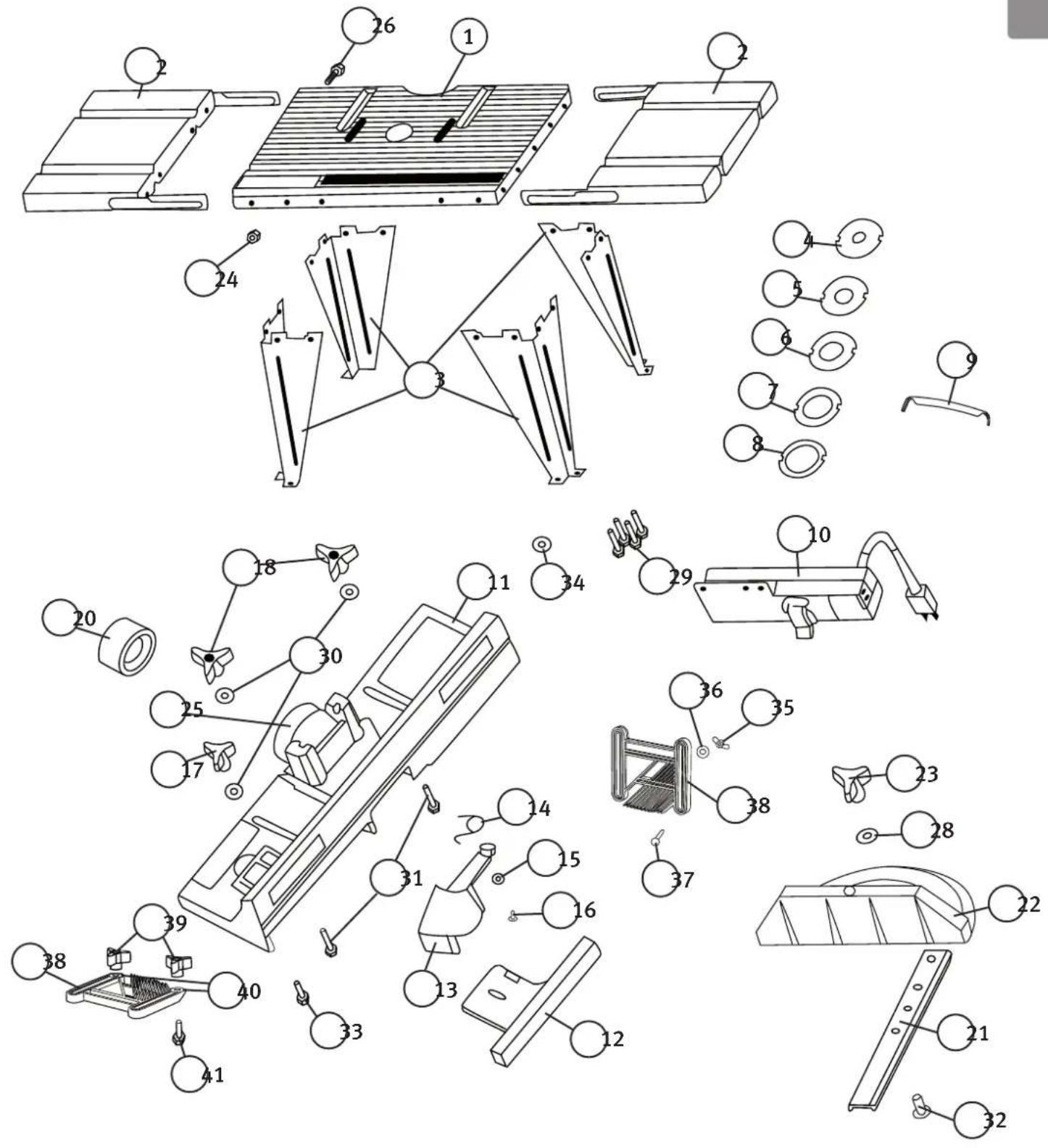
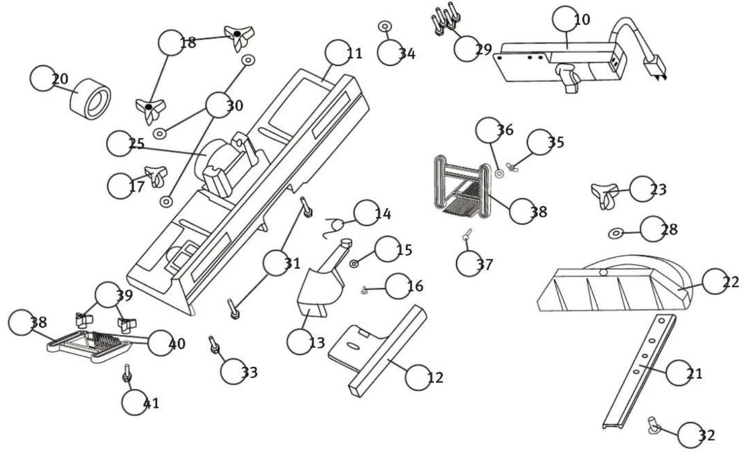
- Router tabletop
- Table extension (2 pcs): Provide extra support for long workpieces.
- Legs (4 pcs)
4, 5, 6, 7 and 8. Table insert (5 pcs) for variable spindle opening. Use the table insert which is just larger than the outside diameter of the cutter bit so as to utilize the suction of the dust extractor as much as possible. - Clamp (4 pcs)
- Combination circuit breaker: On/off, No Volt Release switch
- Guide fence: Adjustable for different workpieces
- Adjustable fence for 11
- Dust hood: Transparent guard so you can see the cutting operation
- Spring
- Washer
- Bolt
- Tri-star knob for fence (small)
- Tri-star knob (large, 2 pcs)
- Dust extraction port insert
- Mitre guide slider
- Mitre guide
- Tri-star knob (small)
- Hex nut (M5)
- Dust extraction port
- Bolt (M5)
- Washer
- Router fastening bolt (M5)
- Washer
- Guide fence bolt (M6 × 40 mm, 2 pcs)
- Mitre guide bolt
- Guide fence bolt (M6 × 25 mm)
- Washer
- Wing nut
- Washer
- Coach bolt M6 × 40 mm
- Featherboard (3 pcs): Adjustable, for holding the workpiece against the table/fence.
- Adjusting knob
- Washer
- Bolt (M6 × 30 mm)
3. Assembly
Note! Before assembling the product, make sure that all the parts are present.
Step 1. Attaching the legs and table extensions
- Lay the router tabletop (1) onto a bench or work surface with the underside up. Bolt the legs (3) onto the inside of the tabletop and the extensions (2) onto the outside. Use bolts (26) and nuts (24).

- Turn over the tabletop (1) and lay a metal rule or straight edge over the tabletop and the extensions (2). Adjust the extensions so that they are level with the tabletop.

natural_image
3D technical diagram of a mechanical assembly with labeled components (no readable text or symbols)Step 2. Attaching the NVR switch
Secure the NVR switch (10) using bolts (26) and nuts (24).

Step 3. Attaching your router to the table
- Read the router's instruction manual before installing it.
- Pass the four router fastening bolts (29) through the tabletop from the upper side and screw on the nuts (24) a few turns so that the bolts hold the router in place whilst the table is turned over.

- Turn the table over and lay it down.
- Wipe off the router's base plate and lay it down onto the underside of the table. There is a round mark on the underside of the table to help centre the router.
- Temporarily remove the nuts (24) from the router fastening bolts.
- Pass the clamps (9) over the bolts (29) and then fit washers (34) and replace the nuts (24).
- The clamps (9) have different length ends, X and Y; turn the clamps so that your router is as secure as possible. Tighten the nuts (24).
- Make sure that the spindle is centred so that it is possible to fasten a router cutter into the chuck and that the plunge function works in the position the router is mounted in.
Warning! Before using the router, always make sure that it is securely fastened to the table and that all the fasteners are tight. Vibrations from the tool can cause the nuts and bolts to loosen.
Step 4. Fitting an insert plate
The table comes with 5 table insert plates (8): Use the table insert which is just larger than the outside diameter of the cutter bit so as to utilize the suction of the dust extractor as much as possible.
• Use the ∅ 13 mm insert plate for cutter bits up to ∅ 10 mm.
• Use the ∅ 20 mm insert plate for cutter bits ∅ 10–16 mm.
- Use the ∅ 25 mm insert plate for cutter bits ∅ 16–22 mm.
- Use the ∅ 32 mm insert plate for cutter bits ∅ 22–28 mm.
• Use the ∅ 38 mm insert plate for cutter bits ∅ 28–35 mm.
• Use no insert plate for cutter bits ∅ 35–41 mm.


natural_image
Illustration of a hand placing ring components into a circuit board (no text or symbols)Step 5. Attaching the fence and adjustable fence
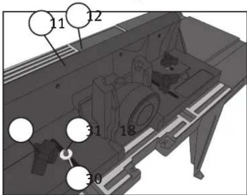
- Slot the adjustable fence (12) into the fixed fence (11).
-
Pass a bolt (33) up through the fixed fence (11) and the adjustable fence (12), fit a washer (30) and cap with a tri-star knob (17).
-
Pass the two guide fence bolts (31) up through the table from below.
- Place the assembled guide fence (11 and 12) over the bolts (31) in the slots in the tabletop (1). Fit washers (30) and tri-star knobs (18) onto the bolts.
- Make sure that the moveable dust hood (13) works properly. It should spring out to its original position when you let go of it.

Step 6. Fitting the featherboards
The featherboards (38) should be adjusted to hold the workpiece against the guide fence. When fitted and adjusted correctly they also serve to prevent/reduce the risk of the workpiece being projected backwards. Attach the featherboards (38) either to the fence (11) or to the tabletop (1).
- Fence attachment: Attach the featherboards (38) to the guide fence using the coach bolt (37), washer (36) and wing nut (35).
- Tabletop attachment: Attach one of the featherboards (38) to the tabletop using bolt (41), washer (40) and tri-star knob (39). Place 2 L-shaped plastic bushings over the bolts in the table's t-slots. They will help keep the featherboard stable.
Note! The featherboard (38) must be mounted in the same direction as the workpiece is to be cut. There is an arrow marked on the featherboard. It should point in the direction of feed.

natural_image
Illustration of a hand operating a mechanical assembly with no visible text or symbols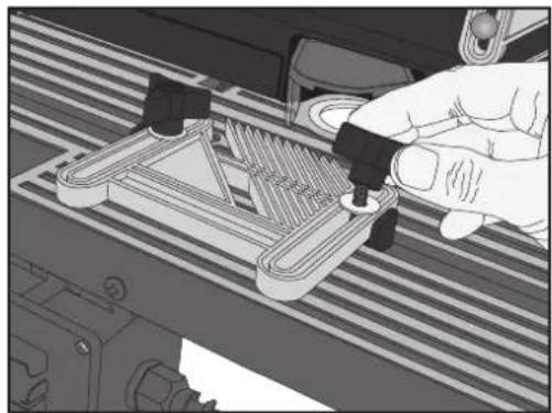
natural_image
Close-up of a hand using a tool to adjust or install a 3D-printed mechanical component (no visible text or symbols)Step 7. Fastening the router table down and preparing it for use
- To prevent the router table for sliding or tipping over, it should be fastened to a bench, table, etc. The foot of each leg has two holes. Use the holes in the feet to screw the legs onto the underlying surface.
- Plug the router into the socket on the bottom of the NVR switch. Note! NEVER plug the router directly into a power point, doing so will bypass the NVR switch – an important safety feature! Make sure that no electric cables are close enough to the spindle for them to be damaged by the rotating cutter bit.
- Connect a dust extraction hose to the port (25) on the rear of the guide fence. The outside diameter of the port sleeve is 65 mm. There is also an extractor port insert (20) with an inside diameter of 30 mm for use with vacuum cleaners.
Warning! Do not connect the router table to a power supply until the table is to be used.

4. Use
4.1 Circuit breaker functions
The circuit breaker has several functions:
Switching on and off
Press the green button [1] to turn the router on; the red button [0] to turn the router off (the on/off switch on the router must also be set to ON in order for it to be operated via the table's circuit breaker).
Emergency stop
The red button [0] protrudes furthest from the switch housing and functions as an emergency stop switch. Hitting this button quickly will switch the router off.
No-Volt Release Switch
The no-volt release switch is an extra safety device which prevents the machine from starting again automatically after a power cut. In order for the machine to start again, the green button [1] must be pressed in.
4.2 Router cutters
Warning! Unplug the router and let the spindle stop completely before performing any service or maintenance.
- Select a router cutter that is sharp and undamaged; remember that a small cutter diameter requires a high speed.
- Note! Do not overtighten the collet nut, the collet can become damaged and be difficult to remove. Check the tightness of the collet before setting the cutting depth (if the collet is loose, the cutter could slip and alter the cutting depth).
- Important! Make sure that at least 20 mm of the cutter shank is secured in the collet chuck. If the shank of the cutter touches the bottom of the collet, it might be difficult to tighten the chuck, in which case it should be pulled out 1–2 mm and then tightened.
4.3 Positioning the guide fence
The guide fence (11) can be mounted either forwards or backwards, but it must be parallel to the T-slot (A) in the tabletop. Measure the distance between both sides of the guide (11) and the slot (A). Make sure that the distance is the same on both sides and then tighten the tri-star knobs.

natural_image
Mechanical assembly diagram showing a cutting machine with labeled component A (no text or symbols beyond labels)4.4 Setting the cutting depth and width
Make your settings in two steps:
Step 1 - Rough setting
Set the desired dimensions minus 1 mm and make a preliminary cut.
Step 2 - Final setting
Measure the workpiece once more and adjust the cutter for the finishing cut.
Routing width: Adjust the width of the cut by setting the guide fence (11) in the correct position.
Cutting depth: Read the router's manual for details of how to set the depth. Check the depth several times during the routing procedure. If the shank of the cutter is pressed into the chuck during routing, the depth of cut will vary.

natural_image
3D mechanical assembly diagram showing a wooden bracket mounted on a workbench with a circular base (no text or symbols visible)4.5 Removing an entire edge
- Set the guide fence (11) to the desired position.
- Set the adjustable fence (12) to the same thickness as you wish to remove.

4.6 Routing recesses and profiles
- The adjustable fence (12) should be pushed all the way into the guide fence (11).
- Set the guide fence (11) to the desired position.
- If the cutter bit has a guide bushing such as a ball bearing, only the guide must be in contact with the workpiece.

natural_image
Close-up of a mechanical component with circular holes and a base plate (no visible text or symbols)5. Disposal
Follow local ordinances when disposing of this product. If you are unsure how to proceed, contact your local authority.
6. Specifications
Intended for Router with base plate up to 157 mm
Size 335 × 850 mm, height 280 mm
Circuit breaker Emergency stop/NVR switch
Fräsbord
ART. NR 18-3193 MODELL RT150/1-UK 40-7991 RT150/1
natural_image
3D technical diagram of a mechanical assembly with labeled components (no readable text or symbols)Steg 2. Montera strömbrytare
natural_image
Illustration of a hand inserting into a ring on a striped electronic circuit board (no text or symbols)natural_image
Illustration of a hand operating a mechanical device with no visible text or symbols
natural_image
Close-up of a hand using a tool to adjust or install a 3D-printed mechanical component (no visible text or symbols)natural_image
Mechanical assembly diagram showing a cutting machine with labeled component A (no text or symbols beyond labels)natural_image
3D mechanical assembly diagram showing a workpiece inserted into a circular base with a wooden block, no text or symbols presentnatural_image
Close-up of a mechanical component with circular holes and a base plate (no visible text or symbols)5. Avfallshantering
3. Montering
natural_image
3D technical diagram of a mechanical assembly with labeled components (no readable text or symbols)Trinn 2. Monter strømbryter
natural_image
Illustration of a hand placing a ring into a slot on a striped surface (no text or symbols)Trinn 5. Monter anslag og justerbart anslag
- Før det justerbare anslaget (12) i det faste anslaget (11).
- Trykk skruen (33) opp gjennom det faste anslaget (11) og det justerbare anslaget (12). Monter brikke (30) og kryssmutter (17).

natural_image
Illustration of a hand pressing down on a guitar fretboard with tools and components (no text or symbols visible)
natural_image
Close-up of a hand using a tool to adjust or install a 3D-printed electronic component (no visible text or symbols)natural_image
Mechanical assembly diagram showing a cutting machine with labeled component A (no text or symbols beyond labels)natural_image
3D mechanical assembly diagram showing a wooden block mounted on a circular base with a textured floor (no text or symbols)natural_image
Close-up of a mechanical component with circular features and a base plate (no visible text or symbols)5. Avfallshåndtering

3. Asennus
natural_image
3D technical diagram of a mechanical assembly with labeled components (no readable text or symbols)natural_image
Illustration of a hand placing a ring onto a striped surface with multiple circular components (no text or symbols)natural_image
Illustration of a hand pressing down on a mechanical component with no visible text or symbols
natural_image
Illustration of a hand using a tool to adjust or install a mechanical component on a striped base (no text or symbols visible)natural_image
Mechanical assembly diagram showing a cutting machine with labeled component A (no text or symbols beyond labels)natural_image
3D mechanical assembly diagram showing a wooden bracket mounted on a workbench with a circular base (no text or symbols visible)natural_image
Close-up of a mechanical component with circular holes and a base plate (no visible text or symbols)5. Kierrätys

3. Montage
natural_image
3D technical diagram of a mechanical assembly with labeled components (no readable text or symbols)
natural_image
Illustration of a hand placing a ring into a slot on a striped surface (no text or symbols)

natural_image
Illustration of a hand operating a mechanical device with no visible text or symbols
natural_image
Illustration of a hand using a tool to adjust or install a 3D-printed component on a striped base (no text or symbols visible)natural_image
Mechanical assembly diagram showing a conveyor belt system with labeled component A (no readable text or symbols)
natural_image
Mechanical assembly diagram showing a wooden block mounted on a circular base with a workpiece inserted (no text or symbols visible)natural_image
Close-up of a mechanical component with circular holes and a base plate (no visible text or symbols)Declaration of Conformity
| Machinery directive2006/42/EC | EMC directive2004/108/EC | Low voltage directive2006/95/EC |
| EN 61029-1:2009 |

Klas Balkow President
Insjön, Sweden, 2012-04-02
SVERIGE
KUNDTJÄNST
Tel:
0247/445 00
Fax:
0247/445 09
E-post: kundservice@clasohlson.se
INTERNET
www.clasohlson.se
BREV Clas Ohlson AB, 793 85 INSJÖN
NORGE
KUNDESENTER
Tlf.:
23 21 40 00
Faks:
23 21 40 80
E-post: kundesenter@clasohlson.no
INTERNETT
www.clasohlson.no
POST
Clas Ohlson AS, Postboks 485 Sentrum, 0105 OSLO
SUOMI
ASIAKASPALVELU
Puh.: 020 111 2222
10 – 13 Market Place
Kingston Upon Thames
Surrey
KT1 1|Z
DEUTSCHLAND
KUNDENSERVICE
- Safety
- General safety instructions for your safety and the safety of others
- Product safety symbols
- Specific safety requirements for routers and router tables
- Features
- Assembly
- Step 1. Attaching the legs and table extensions
- Step 2. Attaching the NVR switch
- Step 3. Attaching your router to the table
- Step 4. Fitting an insert plate
- Step 5. Attaching the fence and adjustable fence
- Step 6. Fitting the featherboards
- Step 7. Fastening the router table down and preparing it for use
- Use
- Circuit breaker functions
- Switching on and off
- Emergency stop
- No-Volt Release Switch
- Router cutters
- Positioning the guide fence
- Setting the cutting depth and width
- Step 1 - Rough setting
- Step 2 - Final setting
- Removing an entire edge
- Routing recesses and profiles
- Disposal
- Specifications
- Fräsbord
- Steg 2. Montera strömbrytare
- Avfallshantering
- Montering
- Trinn 2. Monter strømbryter
- Trinn 5. Monter anslag og justerbart anslag
- Avfallshåndtering
- Asennus
- Kierrätys
- Montage
- Declaration of Conformity
- SVERIGE
- NORGE
- SUOMI
- DEUTSCHLAND
Brand : Cotech
Model : RT150/1
Category : Router