HP 720 - Planer Cocraft - Free user manual and instructions
Find the device manual for free HP 720 Cocraft in PDF.


| Product Type | Planer |
| Brand | Cocraft |
| Model | HP 720 |
| Power Input | 720 W |
| No-Load Speed | 16000 rpm |
| Planing Width | 82 mm |
| Planing Depth | 0 - 2 mm |
| Rebating Depth | 0 - 15 mm |
| Weight | 2.5 kg |
| Dimensions (L x W x H) | 290 x 165 x 150 mm |
| Power Supply | 230 V, 50 Hz |
| Protection Class | Class II (double insulated) |
| Cable Length | 2.5 m |
| Blade Type | HSS (High Speed Steel) |
| Blade Width | 82 mm |
| Dust Collection | Dust bag included |
| Vibration Emission | < 2.5 m/s² |
| Sound Pressure Level | 91 dB(A) |
| Maintenance | Regular blade replacement and cleaning |
| Safety Features | Lock-on switch, blade guard, anti-kickback |
| Spare Parts Available | Blades, carbon brushes, belt, dust bag |
Frequently Asked Questions - HP 720 Cocraft
User questions about HP 720 Cocraft
0 question about this device. Answer the ones you know or ask your own.
Ask a new question about this device
Download the instructions for your Planer in PDF format for free! Find your manual HP 720 - Cocraft and take your electronic device back in hand. On this page are published all the documents necessary for the use of your device. HP 720 by Cocraft.
USER MANUAL HP 720 Cocraft
Read the entire instruction manual carefully and make sure that you fully understand it before you use the equipment. Keep the manual for future reference.
Viktig information:
natural_image
Blue Cocraft HP 720 power tool with black handle and control knob (no visible text or symbols on body)Art.no Model
18-3617
M1B-J2-82X2LM-720
41-1234
M1B-J2-82X2LM-720
Ver. 20190515
Original instructions
Bruksanvisning i original
Originalbruksanvisning
Please read the entire instruction manual before using the product and then save it for future reference. We reserve the right for any errors in text or images and any necessary changes made to technical data. In the event of technical problems or other queries, please contact our Customer Services (see address details on the back).
Safety
General Power Tool Safety Warnings
WARNING Read all safety warnings and all instructions. Failure to follow the warnings and instructions may result in electric shock, fire and/or serious injury.
Save all warnings and instructions for future reference.
The term "power tool" in the warnings refers to your mains-operated (corded) power tool or battery-operated (cordless) power tool.
1) Work area safety
a) Keep work area clean and well lit. Cluttered or dark areas invite accidents.
b) Do not operate power tools in explosive atmospheres, such as in the presence of flammable liquids, gases or dust. Power tools create sparks which may ignite the dust or fumes.
c) Keep children and bystanders away while operating a power tool. Distractions can cause you to lose control.
2) Electrical safety
a) Power tool plugs must match the outlet. Never modify the plug in any way. Do not use any adapter plugs with earthed (grounded) power tools. Unmodified plugs and matching outlets will reduce risk of electric shock.
b) Avoid body contact with grounded surfaces, such as pipes, radiators, ranges and refrigerators. There is an increased risk of electric shock if your body is earthed or grounded.
c) Do not expose power tools to rain or wet conditions. Water entering a power tool will increase the risk of electric shock.
d) Do not abuse the cord. Never use the cord for carrying, pulling or unplugging the power tool. Keep cord away from heat, oil, sharp edges or moving parts. Damaged or entangled cords increase the risk of electric shock.
e) When operating a power tool outdoors, use an extension cord suitable for outdoor use. Use of a cord suitable for outdoor use reduces the risk of electric shock.
f) If operating a power tool in a damp location is unavoidable, use a residual current device (RCD) protected supply. Use of an RCD reduces the risk of electric shock.
3) Personal safety
a) Stay alert, watch what you are doing and use common sense when operating a power tool. Do not use a power tool while you are tired or under the influence of drugs, alcohol or medication. A moment of inattention while operating power tools may result in serious personal injury.
b) Use personal protective equipment. Always wear eye protection.
Protective equipment such as dust mask, non-skid safety shoes, hard hat, or hearing protection used for appropriate conditions will reduce personal injuries.
c) Prevent unintentional starting. Ensure the switch is in the off-position before connecting to power source and/or battery pack, picking up or carrying the tool. Carrying power tools with your finger on the switch or energising power tools that have the switch on invites accidents.
d) Remove any adjusting key or wrench before turning the power tool on.
A wrench or a key left attached to a rotating part of the power tool may result in personal injury.
e) Do not overreach. Keep proper footing and balance at all times. This enables better control of the power tool in unexpected situations.
f) Dress properly. Do not wear loose clothing or jewellery. Keep your hair, clothing and gloves away from moving parts. Loose clothes, jewellery or long hair can be caught in moving parts.
g) If devices are provided for the connection of dust extraction and collection facilities, ensure these are connected and properly used. Use of dust collection can reduce dust-related hazards.
4) Power tool use and care
a) Do not force the power tool. Use the correct power tool for your application. The correct power tool will do the job better and safer at the rate for which it was designed.
b) Do not use the power tool if the switch does not turn it on and off. Any power tool that cannot be controlled with the switch is dangerous and must be repaired.
c) Disconnect the plug from the power source and/or the battery pack from the power tool before making any adjustments, changing accessories, or storing power tools. Such preventive safety measures reduce the risk of starting the power tool accidentally.
d) Store idle power tools out of the reach of children and do not allow persons unfamiliar with the power tool or these instructions to operate the power tool. Power tools are dangerous in the hands of untrained users.
e) Maintain power tools. Check for misalignment or binding of moving parts, breakage of parts and any other condition that may affect the power tool's operation. If damaged, have the power tool repaired before use.
Many accidents are caused by poorly maintained power tools.
f) Keep cutting tools sharp and clean. Properly maintained cutting tools with sharp cutting edges are less likely to bind and are easier to control.
g) Use the power tool, accessories and tool bits etc. in accordance with these instructions, taking into account the working conditions and the work to be performed. Use of the power tool for operations different from those intended could result in a hazardous situation.
5) Service
a) Repairs and service should only be performed by qualified persons, and only with original spare parts. This guarantees the safety of the electrical hand tool.
Specific Safety Requirements for Planers
- Wait for the cutter to stop before setting the tool down. An exposed rotating cutter may engage the surface leading to possible loss of control and serious injury.
- Hold the power tool by insulated gripping surfaces only, because the cutter may contact its own cord. Cutting a "live" wire may make exposed metal parts of the powertool "live" and could give the operator an electric shock.
- Use clamps or another practical way to secure and support the workpiece to a stable platform. Holding the work by your hand or against the body leaves it unstable and may lead to loss of control.
- Hold power tool by insulated gripping surfaces, because the belt may contact its own cord. Cutting a "live" wire may make exposed metal parts of the power tool "live" and could give the operator an electric shock.
Guide to Safety Symbols

Read the entire instruction manual.

Always use ear protection.

Always use safety glasses or a visor and wear a dust mask.
Product description
- Handle
- Ventilated motor housing
- Rebating depth guide
- Rebating depth guide locking lever
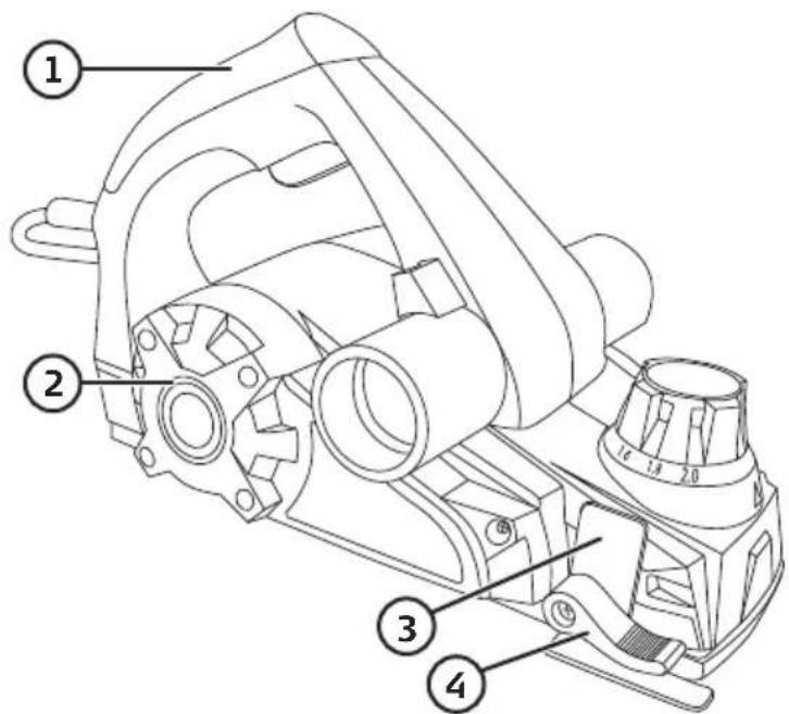
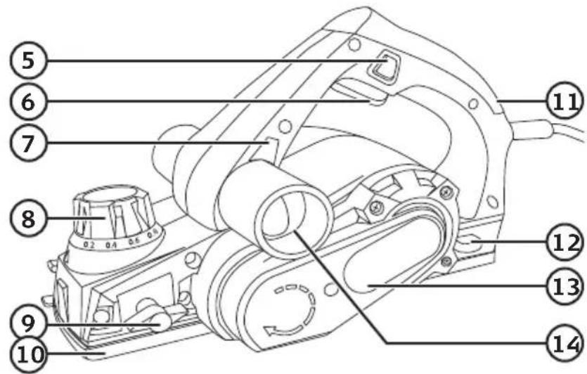
- Trigger lock button
- Power trigger
- Chip ejector selector button
- Planing depth adjuster with scale
- Parallel guide locking knob
- Soleplate
- Power indicator, lights when planer is energised
- Blade tool holder
- Drive belt cover
- Chip ejector
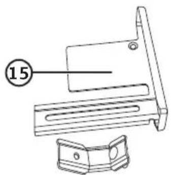
- Parallel guide
Operating instructions
Warning:
• Always unplug the planer before adjusting the cutting depth or cutting width.
- Make sure that the workpiece is securely fastened to the work bench and that the work bench is stable and won't move.
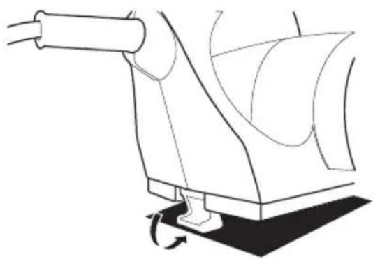
- Lower the parking rest on the rear of the planer when you stop work. It protects the blade when it is not in use.
natural_image
Technical line drawing of a mechanical component with a curved arrow indicating rotation (no text or symbols)Planing a flat surface
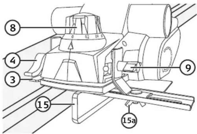
Turn the planing depth adjuster (8) to the desired depth. Plug the planer into the wall socket. Hold in the trigger lock button (5) and then pull the power trigger (6).
Warning: Never adjust the planing depth while planing; doing so will result in an uneven depth of cut. Always return the planing depth to 0 when you have finished work to avoid an incorrect setting when beginning your next planing task.
Rebating
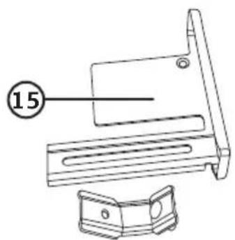
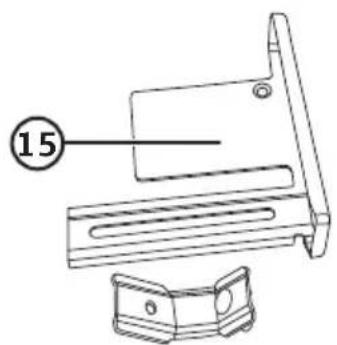
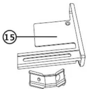
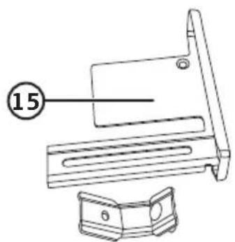
Attach the parallel guide (15) as shown in the figure above and fasten it using the locking knob (9).
Adjusting the rebating depth
Set the rebating depth guide (3) to the desired depth and lock it using the locking lever (4).
Adjusting the cutting depth
Turn the planing depth adjuster (8) to the desired setting.
Warning: Never adjust the planing depth while planing; doing so will result in an uneven depth of cut. Always return the planing depth to 0 when you have finished work to avoid an incorrect setting when beginning your next planing task.
Adjusting the rebating width
The rebating width is adjusted using the parallel guide. Loosen the wing nut (15a), set the parallel guide to the desired position and then tighten the wing nut again.
Chamfering
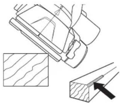
The V-grooves on the bottom of the soleplate makes it possible to chamfer the edges of the workpiece.
natural_image
Technical line drawing showing a mechanical component with cross-sections and an arrow indicating direction (no text or symbols)Work procedure
In order to achieve a smooth, even surface on the workpiece it is best to begin with a coarse/deeper cut and then reduce the cutting depth and finish with a finer cut. Hold the planer firmly and feed it slowly and steadily over the workpiece. Switch off and unplug the planer as soon as you have finished work.
Small workpieces
Make sure that small workpieces are firmly clamped or held in a vice.
Care and maintenance
• Always unplug the mains lead from the wall socket before any servicing or cleaning.
- Wipe the planer clean with a dry cloth and vacuum clean if necessary.
- Check that the holes in the motor housing ventilation (2) are free from dust and debris.
- Unplug the planer and store it in a dry environment out of children's reach whenever it is not in use.
Changing blades
Warning: Always unplug the mains lead from the wall socket before any servicing or maintenance.
- When the planer blades have been used for a while they might be too blunt to produce a clean cut and smooth finish. Continued use of blunt or worn blades will result in a poor surface finish and could overload the motor. The blades should therefore be checked regularly and turned over or replaced if necessary.
- The tungsten carbide tipped blades are double-edged and can be turned over and the other edge used once one of the edges is worn.
- The tool for changing or adjusting the blades is kept in the blade tool holder (12).
- The cutting depth of the blade seldom needs to be adjusted. Do not undo the set screws (20) until you are certain that the cutting depth needs adjusting.
Disassembling and assembling the blade
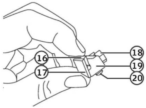
Blade holder assembly
- Blade
- Drum plate
- Clamping screw
- Set plate
- Set screw
Detaching the dust collector
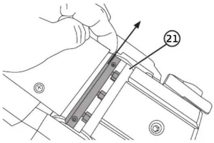
- Undo the three clamping screws (18), hold down the spring-loaded guard and slide the blade (16) out of the set plate (19). You can also choose to slide the entire blade holder out of the blade drum (21) and reverse/change the blade when the blade holder is loose.
Note: Do not move the set screws (20) and pay attention to how the parts are assembled.
- If the blade holder is removed the parts can easily disassemble. Make sure that all the parts are in the right place when the blade holder is put back.
natural_image
Technical diagram showing a mechanical assembly with arrows indicating direction of movement (no text or symbols present)Turning the blades over/Fitting the blades
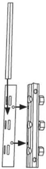
- Turn the blade over and fit it into the blade holder.
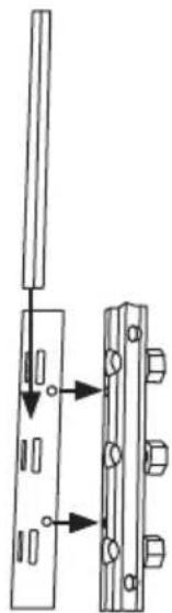
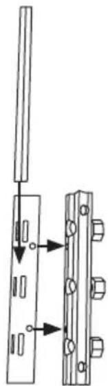
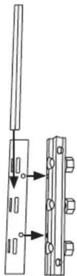
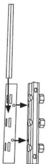
- Make sure that the slot in the blade lines up with the guides on the drum plate. See the figure above. There are also two protrusions on the drum plate that must line up with two holes in the set plate. See the figure above.
- Place the assembled blade holder into the blade drum. Make sure that the blade holder is in the centre of the blade drum.
- Tighten the three clamping screws. Turn the blade drum by hand to make sure that it can rotate freely before switching the planer on.
Note: If you adjust the cutting depth, the edge of the blade must not protrude more than 1.1 mm from the drum. It is important that both blades have the same setting. After changing or adjusting the blades, make sure that all the screws are tight.
Changing the drive belt
Warning: Always unplug the mains lead from the wall socket before any servicing or maintenance.
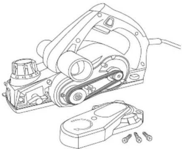
- Undo the two screws holding the drive belt cover and remove it. Remove the drive belt. Clean both belt pulleys.
- Place the new drive belt onto the small pulley.
- Work the other end of the drive belt up over the large pulley while rotating the pulley by hand.
- Make sure that the belt sits properly in the grooves on the pulley wheels.
- Refit the belt cover.
natural_image
Technical line drawing of a mechanical device with rollers and a clamp, showing no text or symbolsTroubleshooting guide
| The planer won’t start. • Make sure that the mains lead is undamaged and properly connected to the wall socket.• Check that the wall socket is live. |
| Poor performance.The planer is overheated. Refer to the Changing blades section above.• Check that the holes in the motor housing ventilation (2) are free from debris. |
| The planer switches on but the drum doesn’t rotate. • The drive belt is defective.Refer to the Changing the drive belt section above. |
Responsible disposal
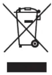
This symbol indicates that this product should not be disposed of with general household waste. This applies throughout the entire EU. In order to prevent any harm to the environment or health hazards caused by incorrect waste disposal, the product must be handed in for recycling so that the material can be disposed of in a responsible manner. When recycling your product, take it to your local collection facility or contact the place of purchase. They will ensure that the product is disposed of in an environmentally sound manner.
natural_image
Symbol of a trash bin crossed with no text or numbers, representing waste sorting or disposal (no text present)Specifications
Rated voltage 230–240 V AC, 50 Hz
Power 720 W
No-load speed 16 000 rpm
Max planing width 82 mm
Planing depth 0–2 mm
Rebating depth 0–18 mm
Sound pressure level (LpA) 86 dB(A), K = 3 dB(A)
Sound power level (LwA) 97 dB(A), K = 3 dB(A)
Vibration 4.7 m/s ^2 , K = 1.5 m/s ^2
Weight 3 kg
Elhyvel
Art.nr 18-3617 Modell M1B-J2-82X2LM-720
41-1234 M1B-J2-82X2LM-720
Användning
Varning!
natural_image
Technical line drawing of a mechanical component with motion arrows indicating rotation (no text or symbols)Hyvling av plan yta
natural_image
Technical line drawing showing a mechanical component with cross-sections and an arrow indicating direction (no text or symbols)Arbetssätt
natural_image
Technical diagram showing a mechanical assembly with two parts, one being inserted and the other assembled, both with arrows indicating direction (no text or symbols present)natural_image
Technical line drawing of a mechanical device with pulleys and accessories (no text or symbols)Felsökningsschema
natural_image
Symbol of a trash bin crossed with no text or numbers, representing environmental restriction (no text present)Specifikationer
Nätanslutning 230–240 V AC, 50 Hz
Effekt 720 W
Bruk
Advarsel!
natural_image
Technical line drawing of a mechanical component with a rotating base and shaft (no text or symbols)natural_image
Technical line drawing showing a mechanical component with cross-sections and a close-up of a wooden block (no text or symbols)Arbeidsmåte
natural_image
Technical diagram showing a mechanical assembly with two parts, one with a handle and arrow indicating direction (no text or symbols)natural_image
Technical line drawing of a mechanical device with pulleys and accessories (no text or symbols)Feilsøking
natural_image
Symbol of a trash bin crossed with no visible text or labelsSpesifikasjoner
Nettspenning 230–240 V AC, 50 Hz
Effekt 720 W
Omdreininger/minutt 16 000 (ubelastet)
Maks høvelbredde 82 mm
Maks spondybde 0–2 mm
Falsdybde 18 mm
Käyttö
Varoitus
natural_image
Technical line drawing of a mechanical component with motion arrows indicating rotation (no text or symbols)natural_image
Technical line drawing showing a mechanical component with cross-sections and an arrow indicating direction (no text or symbols)Työskentely
natural_image
Technical diagram showing a mechanical assembly with two parts, one being inserted and the other assembled, both with arrows indicating direction (no text or symbols present)natural_image
Technical line drawing of a mechanical device with pulleys and accessories (no text or symbols)Vianhakutaulukko
natural_image
Symbol of a trash bin crossed out by two crossed lines, with no text or labels present.Tekniset tiedot
Benutzung
Warnung!
natural_image
Technical line drawing of a mechanical component with motion arrows indicating rotation (no text or symbols)natural_image
Technical line drawing showing a mechanical component with cross-sections and a close-up of a wooden block (no text or symbols)Arbeitsweise
natural_image
Technical diagram showing a mechanical assembly with two parts, one being inserted and the other assembled, both with arrows indicating direction (no text or symbols present)natural_image
Technical line drawing of a mechanical device with pulleys and components, no text or symbols presentFehlersuche
natural_image
Symbol of a trash bin crossed with no text or labels, accompanied by a blank rectangular block below (no text or symbols present)Technische Daten
Declaration of Conformity
Declares that this product complies with the requirements of the following directives and standards
Machinery Directive 2006/42/EC
EN 62841-1:2015
EN 62841-2-14:2015
EMC Directive 2014/30/EU
EN 55014-1:2017
EN 55014-2:2015
EN 61000-3-2:2014
EN 61000-3-3:2013
Low Voltage Directive 2014/35/EU
Elliner Widushim
Ellinor Wickström
Product Compliance Manager
Insjön, Sweden, 2019-05-15
CLAS OHLSON AB, SE-793 85 INSJÖN, SWEDEN
Sverige
Postal 10 - 13 Market Place
Kingston Upon Thames
Surrey
KT1 1JZ
Deutschland
Kundenservice Hotline: 040 2999 78111
E-Mail: kundenservice@clasohlson.de
Homepage
www.clasohlson.de
- Viktig information:
- Safety
- General Power Tool Safety Warnings
- 1) Work area safety
- 2) Electrical safety
- 3) Personal safety
- 4) Power tool use and care
- 5) Service
- Specific Safety Requirements for Planers
- Guide to Safety Symbols
- Product description
- Operating instructions
- Warning:
- Planing a flat surface
- Rebating
- Adjusting the rebating depth
- Adjusting the cutting depth
- Adjusting the rebating width
- Chamfering
- Work procedure
- Small workpieces
- Care and maintenance
- Changing blades
- Disassembling and assembling the blade
- Blade holder assembly
- Detaching the dust collector
- Turning the blades over/Fitting the blades
- Changing the drive belt
- Troubleshooting guide
- Responsible disposal
- Specifications
- Elhyvel
- Användning
- Varning!
- Hyvling av plan yta
- Arbetssätt
- Specifikationer
- Bruk
- Advarsel!
- Arbeidsmåte
- Spesifikasjoner
- Käyttö
- Varoitus
- Työskentely
- Vianhakutaulukko
- Tekniset tiedot
- Benutzung
- Warnung!
- Arbeitsweise
- Fehlersuche
- Technische Daten
- Declaration of Conformity
- Sverige
- Deutschland
Brand : Cocraft
Model : HP 720
Category : Planer