
HI 2000 - Generator Cocraft - Free user manual and instructions
Find the device manual for free HI 2000 Cocraft in PDF.


| Product Type | Portable Generator |
| Brand | Cocraft |
| Model | HI 2000 |
| Rated Power (Continuous) | 2000 W |
| Peak Power (Starting) | 2500 W |
| Engine Type | 4-stroke, single cylinder |
| Fuel Type | Gasoline (unleaded) |
| Fuel Tank Capacity | 4 L |
| Runtime at 50% Load | Approx. 8 hours |
| Starting System | Recoil start (manual) |
| Outlets | 2 x 120V AC, 1 x 12V DC |
| Noise Level (at 7m) | 65 dB(A) |
| Dimensions (L x W x H) | 50 x 40 x 40 cm |
| Weight | 28 kg |
| Safety Features | Low oil shutdown, automatic voltage regulator, circuit breaker |
| Warranty | 2 years |
| Maintenance | Oil change every 50 hours, air filter cleaning every 25 hours |
| Spare Parts Availability | Filters, spark plugs, oil, and more available from Cocraft retailers |
| Repairability | Serviceable by authorized repair centers |
| Included Accessories | Oil funnel, spark plug wrench, user manual |
Frequently Asked Questions - HI 2000 Cocraft
User questions about HI 2000 Cocraft
0 question about this device. Answer the ones you know or ask your own.
Ask a new question about this device
Download the instructions for your Generator in PDF format for free! Find your manual HI 2000 - Cocraft and take your electronic device back in hand. On this page are published all the documents necessary for the use of your device. HI 2000 by Cocraft.
USER MANUAL HI 2000 Cocraft
Read the entire instruction manual carefully and make sure that you fully understand it before you use the equipment. Keep the manual for future reference.
Viktig information:
natural_image
Line drawing of a Coocraft electric generator (no text or symbols on the device itself)Art.no Model
40-8889
IG2400S
Ver. 20180726
Original instructions
Bruksanvisning i original
Originalbruksanvisning
Please read the entire instruction manual before using the product and save it for future reference. We reserve the right for any errors in text or images and any necessary changes made to technical data. If you have any questions regarding technical problems please contact our Customer Services.
Contents
Safety....3
Key to warning symbols 4
Intended application ....4
Product description....4
Operating instructions 6
Preparations 6
Starting the engine (cold start) 6
Economy mode....7
Switching the engine off 8
Connecting electrical devices 8
Using the 230 V AC sockets ....8
12 V DC socket for charging batteries 8
Care and maintenance....9
Maintenance schedule....9
Engine oil....9
Air filter....10
Spark plug....10
Emptying the fuel system....11
Checking the cooling system .... 11
Checking the starting system 11
Cleaning the generator....11
Transportation 11
Storage 12
Responsible disposal.... 12
Specifications 13
Generator 13
Engine....13
Other....13
Safety
When in operation, the exhaust from the generator contains poisonous carbon monoxide gas. Carbon monoxide is both odourless and colourless and may be present even if you do not see or smell gas. Breathing this poisonous gas can lead to headaches, dizziness, drowsiness, loss of consciousness and eventually death.
- The generator must only be used outdoors in non-confined areas.
- Keep adequate clearance around the generator to allow for proper ventilation. Do not cover.
The generator may emit highly flammable and explosive fuel fumes which can cause severe burns or even death. A nearby naked flame can lead to an explosion even if not directly in contact with the fuel.
- Do not operate the generator near a naked flame.
- Do not smoke near the generator.
• Always operate the generator on a dry, firm and level surface. - Always switch the generator off before refuelling it. Let the generator cool down for at least 2 minutes before removing the fuel tank cap. Loosen the cap slowly to relieve pressure in the fuel tank.
- Do not fill the fuel tank to the top, the fuel could expand during operation. Always wipe up any spilt fuel before starting the generator.
• Always empty the fuel tank before storing or transporting the generator. - Before transporting, close the fuel cut-off valve and disconnect the spark plug lead.
The generator produces powerful, potentially lethal voltage.
- Only electrical devices should be plugged into this generator, either directly or with an extension lead. Never connect the generator to a building's electrical system without the help of a qualified electrician. Connecting the generator in the wrong way can create feedback into the mains network resulting in an electrocution hazard. The connections must comply to all local wiring regulations and codes of practice.
- Do not connect the generator to any other power source such as another generator or inverter.
- Use a residual current device (RCD) in highly conductive areas such as on metal platforms or roofs.
- Do not use the generator in wet conditions or wet environments.
- Do not operate the generator near water such as pools, beaches or jetties.
- Do not touch bare wires or electrical sockets.
- Do not allow children or non-qualified persons to operate the generator.
The generator becomes extremely hot during use. Temperatures near the exhaust can exceed 65 °C.
- Do not touch hot surfaces. Observe all the warnings on the generator denoting hot surfaces.
- Allow the generator to cool after use before touching the engine or other areas that have become hot during operation.
Misuse of this generator can damage it or shorten its life.
- Use the generator only for its intended purpose.
- Make sure the generator is on a level surface.
-
Allow the generator to run for several minutes before connecting any electrical devices.
-
Promptly turn off and disconnect any malfunctioning electrical devices.
- Do not exceed the capacity of the generator by connecting electrical devices requiring a combined power in excess of the wattage capacity of the generator.
- Do not turn on electrical devices until after they are connected to the generator.
- Turn off all connected electrical devices before switching the generator off.
- The generator is fitted with an earth terminal connected to the frame, engine chassis and the earth pins of the socket outlets. Consult an electrician regarding the wiring regulations applicable for your intended use of the generator.
Key to warning symbols

Warning: Read the entire instruction manual before use.
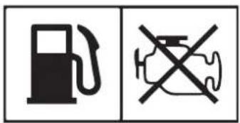
Switch the engine off and allow it to cool before refuelling. Never refuel whilst the engine is running.

Hot surfaces, the silencer becomes very hot. Keep flammable materials away from the generator.

The generator must not be used indoors or in closed areas, ensure that the working area is well-ventilated. Carbon monoxide (CO) danger.
Intended application
The generator is intended to be used with: normal electrical appliances such as lights and power tools, and also TV sets and computers. Do not connect electrical appliances that use more than 1800 W. Henceforth, connected electrical appliances will be referred to as the applied load.
Product description
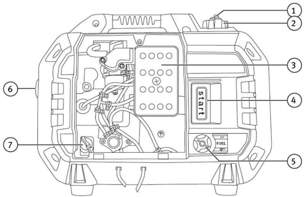
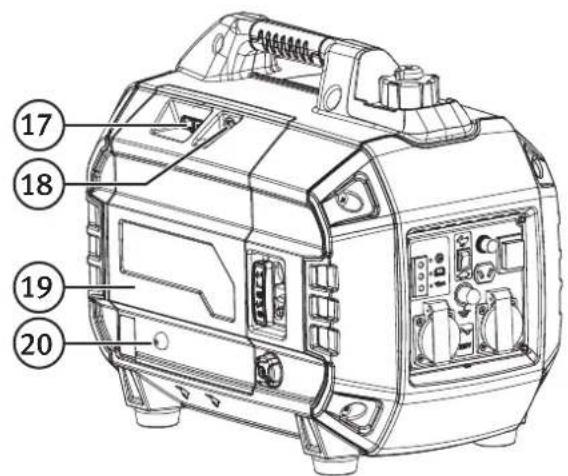
- Fuel tank cap vent
- Fuel tank cap
- Air filter
- [START] Starter handle
- [FUEL, ON/OFF] Petrol tap on/off
- Exhaust
- Oil filler cap/dipstick
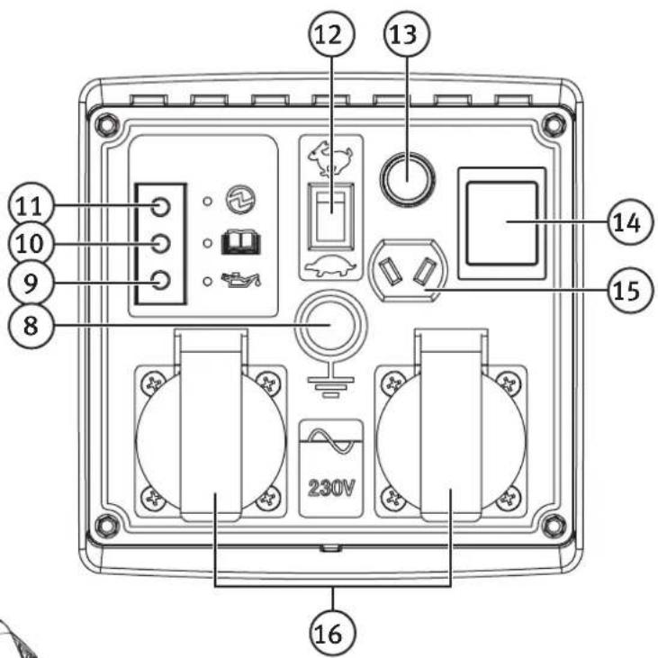
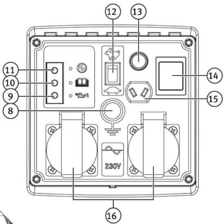
- Earth rod connection
- Low oil indicator
- Overload indicator
- Outputindicator
- Mode selector switch: Economy mode (low idle speed), Normal mode
- DC socket overload protection circuit breaker
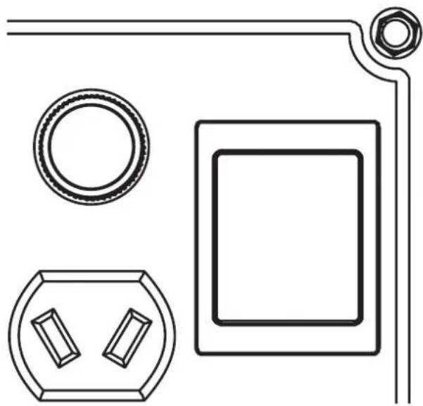
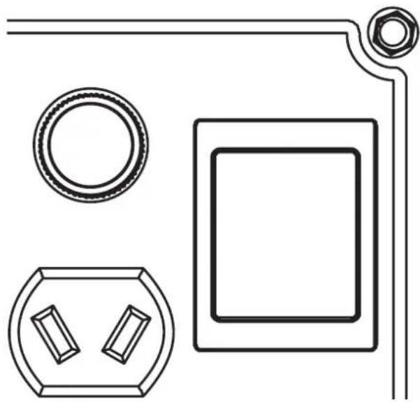
- [ON/OFF] Engine on/off switch
- 12 V DC socket
- 230 V AC socket
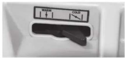
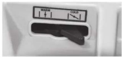
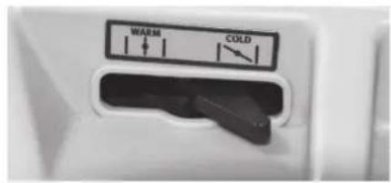
- [Choke, WARM-COLD] The choke is closed in the COLD position (cold start)
- Maintenance cover retaining screw
- Maintenance cover
- Primer
Operating instructions Preparations
Check the oil level before switching the generator on
- Remove the screw (18) fastening the maintenance cover (19) (the big cover next to the starter handle).
- Make sure that the generator is on a flat and level surface. Remove the oil filler cap (7) and wipe the dipstick clean.
- Fully insert the dipstick into the filler neck without screwing the cap back on.
- Remove the dipstick and read the oil level. There is a minimum level mark about 1 cm up from the bottom of the dipstick. The dipstick hole is also the oil filler neck. The oil level should be between the mark on the dipstick and the bottom of the filler bottom of the thread on the oil filler neck.
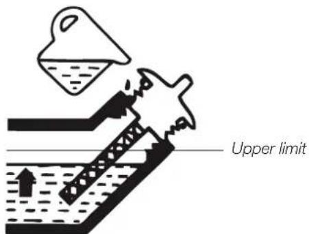
- If the oil level is low add more oil. SAE 10W-30 engine oil for 4-stroke engines is recommended for normal use (-5–25 °C). The oil should have an API service class rating of at least SJ.
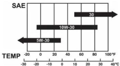
bar
| Temperature Range | Value | | :--- | :--- | | 5W-30 | -20 | | 10W-30 | 80 | | 30 | 60 | | SAE | 40 |Refuelling
- Make sure that the generator is flat and level and in a well-ventilated place. Unscrew the fuel cap (2).
- Only use fresh, clean petrol with an octane rating of at least 95 and containing no more than 10 % ethanol. The use of fuel with a content of ethanol higher than 10 % could lead to engine damage which is not covered by the guarantee.
- Screw the fuel cap back on, close the air vent (1) if the generator is not to be used straight away.
- Wipe up any fuel spills immediately.
Starting the engine (cold start)
The generator should be placed on a firm, flat surface with good ventilation and at least 1 metre away from building walls and ceilings.
Note: The generator engine cooling air inlet vents are located on the underside of the generator. The generator must not be placed on any soft material which could block the air inlets and cause the engine to overheat.
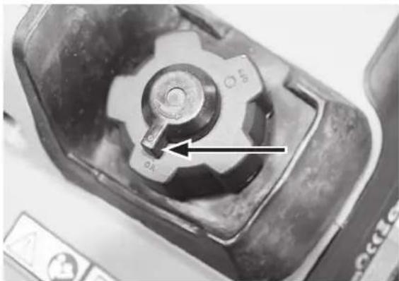
- Open the fuel tank cap vent by turning it clockwise to the ON position.
natural_image
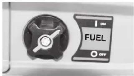
Close-up of a mechanical component with a central knob and arrow indicator (no readable text or symbols)- Turn the fuel supply on by switching the petrol tap to ON.
- Press the primer 5–6 times.
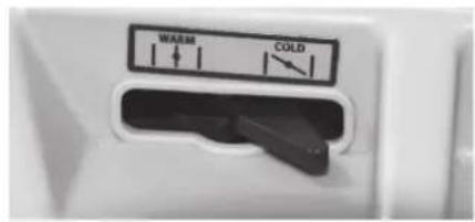
- Set the choke to COLD.
natural_image
Close-up of a fuel switch with ON/OFF labels (no readable text beyond 'FUEL' and symbols)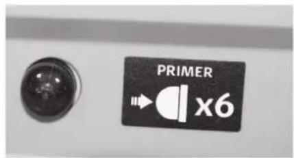
- Set the engine switch to the ON position.
- Slowly pull the starter handle (4) until a slight resistance is felt. Then pull the handle briskly to start the engine. Do NOT let go of the starter handle as soon as the engine starts so that it snaps back against the generator. Let it recoil gently to prevent any damage to the starter.
- When the engine has started: After about 10 seconds, set the choke to the half-open position for a few seconds before setting it to WARM.
- Allow the engine to run for a couple of minutes to ensure that it is running smoothly before connecting the applied load or before switching to economy mode.
△ Important:
- If it is very cold when the generator is to be started, the choke might need to be left set to "COLD" for longer and in the half-open position even longer.
- If the generator is restarted before it has cooled down completely, the choke might not be needed for such a long time or not at all, depending on the ambient temperature.
natural_image
Pure technical line drawing of electrical components without any text or symbolsEconomy mode
The generator has a selectable economy mode which reduces fuel consumption by lowering the engine idling speed to a lower level than normal when the applied load is reduced or turned off. The engine speed will increase again automatically if the applied load increases. Activate the economy mode by setting the mode selector switch (12) to OFF (4).
Do not select the economy mode if the applied load requires a high start-up power or high running power, the engine might not be able to reach enough speed resulting in voltage fluctuations which might damage the applied load.
Do not select the economy mode for applied loads that require only intermittent operation, momentary power, or loads which will be turned on and off quickly. In these cases the normal mode should be used and the mode selector set to ON ( ).
Switching the engine off
To stop the engine in an emergency: set the engine switch to 0 OFF.
Stopping the engine normally:
- Turn off all applied load devices.
- Set the engine switch to the 0 OFF position.
- Close the fuel tank air vent (1).
- Turn the fuel supply off by switching the petrol tap to OFF.
Connecting electrical devices
Before making any connections, first inspect the electrical device and any cables for damage. All cables and connectors must be approved for outdoor use.
If an applied load begins to act abnormally or stops suddenly:
- Switch it off and disconnect it from the generator immediately.
- Investigate the cause of the problem.
- Make sure that the rated power of the applied load does not exceed the maximum power of the generator.
Do not exceed the generator's rated power of 1800 W (continuous operation).
Using the 230 V AC sockets
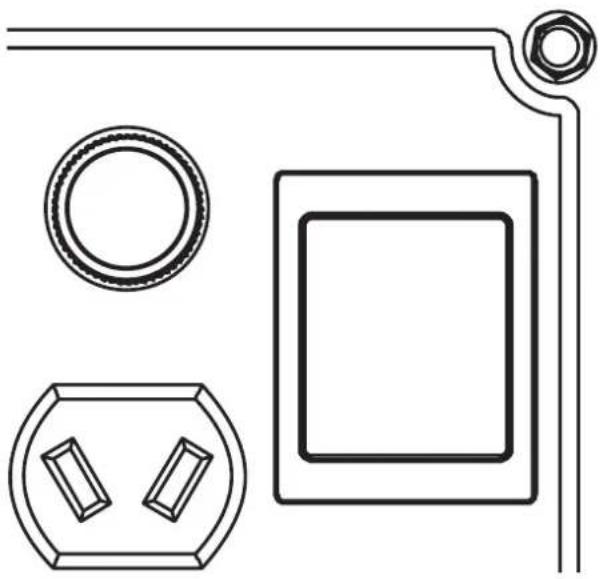
- Start the engine and make sure that the green output indicator light (11) comes on.
- Plug the applied load into the AC socket/s.
Bear in mind that most devices require more than their rated wattage for start-up than during normal operation.
Overload
- If the generator is overloaded, if the applied load is short-circuited or if the generator is overheated, the red overload indicator light (10) will come on.
- Approximately 5 seconds later, the current to the socket outlets will be cut off. The red overload indicator light will stay on.
- The green output indicator light (11) will go out.
- Switch the engine off and investigate the cause of the problem.
- Then engine must be restarted to reset the generator.
12 V DC socket for charging batteries
The 12 V outlet is only intended for charging lead-acid batteries such as car batteries >60 Ah. The DC output current and voltage are not regulated and will vary depending on the speed of the engine and whether or not the economy mode is activated. The maximum charging current is 8.3 A.
Note: Battery charging must be supervised and discontinued manually otherwise there is a risk of the battery fluid boiling and damaging the battery. Whilst a battery is being charged it will emit an explosive oxyhydrogen gas mixture. Batteries should be charged in well-ventilated areas, and well away from sources of ignition. For more efficient car battery charging, we recommend that a 230 V AC car battery charger is connected to the 230 V AC outlet of the generator.
Note: Do not connect lead-acid batteries with capacities less than 60 Ah.
The 12 V outlet is unregulated, i.e. the output voltage depends on the speed of the engine and the load on the generator. If the economy mode is selected and no applied load is connected to the 230 V AC socket, the charging current is 1/3 of the rated current (approx. 2.7 A). The 12 V socket is equipped with a circuit breaker (13) which trips if the socket is overloaded. If this happens, disconnect the battery and investigate the cause. Reset the circuit breaker by pushing the button in.
Warning:
First connect the battery charging lead to the DC socket of the generator and then to the battery.
Care and maintenance
Good maintenance is essential for safe, economical and trouble-free operation and a long service-life.
Maintenance schedule
Caution!
Never service the generator whilst the engine is running. Switch the generator off and let it cool.
| Check Action | Before every use | After 1 month or 20 hours | Every 3 months or 50 hours | Every 6 months or 100 hours | Every 12 months or 300 hours | |
| Spark plug | Check, adjust gap and replace if necessary | • | ||||
| Engine oil | Check level • | |||||
| Replace • • | ||||||
| Air filter | Clean and replace if necessary | •* | ||||
| Valve clearance | Check and adjust when engine is cold | • | Have checked and adjusted by qualified tradesman | |||
| Fuel line | Check for cracks and leaks | • | ||||
| Carburettor | Check choke operation | • | ||||
| Cooling system | Check that the ventilation openings are clear | • | ||||
| Starting system | Check starter cord for wear | • | ||||
| Fittings and fasteners | Tighten all screws and nuts | • |
* If the generator is in a dusty environment, the filter should be cleaned more often.
Engine oil
If the oil level is too low, the generator shuts off automatically to prevent damage. Check the oil level prior to every use to ensure that there is enough.
Engine oil gradually loses the lubricating, cooling and cleaning properties it has when it is new and therefore needs to be changed periodically.
Changing the oil
Change the oil whilst the engine is warm as the oil drains out easier. Be careful – the engine oil might be hot. The engine oil is drained out and added via the oil filler neck where the dipstick is located.
-
Switch the engine off and close the fuel tank air vent (1) in order to prevent fuel leaks.
-
Undo the maintenance cover screw and remove the cover (19).
-
Place a suitable waste oil container on the ground in front of the oil filler opening.
-
Unscrew the oil filler cap/dipstick (7) and tilt the generator.
-
Drain the oil into the container.
-
Make sure that the generator is on an even, level surface.
-
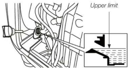
Using a funnel, fill the oil tank up to the top of the oil filler neck with new SAE 10W-30 oil. It is important that the generator is level to ensure the correct amount of oil.
-
Refit the oil filler cap and the maintenance cover.
Note: Used engine oil is a damaging source of environmental pollution. Do not pour used engine oil down your drain or sink. Place it in a leak proof container and dispose of it in an environmentally-friendly way. If you are unsure how to proceed, contact your local authority.
Air filter
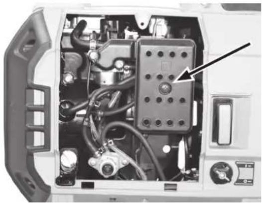
Regular air filter service will ensure that the correct amount of air flows into the carburettor. Regular checks should be made to ensure that the air filter is not blocked.
natural_image
Interior view of a vehicle's door frame showing internal components like hoses, cables, and a control panel (no text or symbols visible)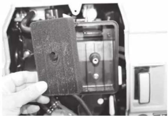
natural_image
Hand holding a small electronic device with a black cover, mounted on a device casing (no visible text or symbols)-
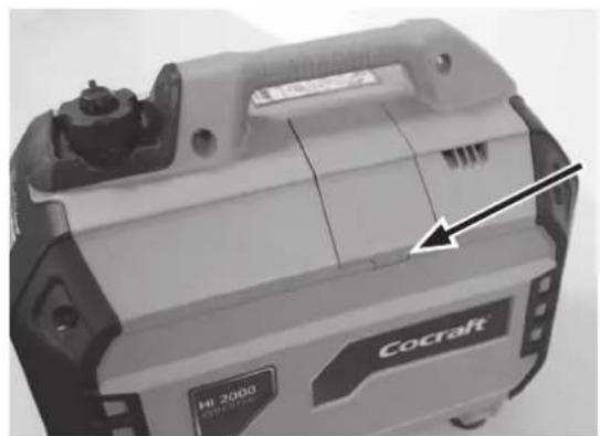
Undo the maintenance cover screw (18) and remove the cover (19).
-
Remove the retaining screw from the air filter cover.
-
Remove the filter and wash it in a solution of warm water and mild detergent. Squeeze the filter and allow it to dry completely before refitting it.
Spark plug
If the spark plug is in good condition it should not be cracked or pitted or coated in heavy deposits. Checking the spark plug:
- Switch the engine off and let it cool.
- Remove the spark plug cover on the rear of the generator.
- Remove the spark plug cap from the spark plug.
- Use a spark plug spanner (supplied) to remove the spark plug.
- Inspect the spark plug. If it is in poor condition, with a cracked or chipped insulator or eroded electrodes, it should be replaced. The correct type of plug is listed under Specifications. Check the spark plug gap and adjust it if necessary.
- If you are going to use the same spark plug again, clean it using a wire brush before refitting it.
- Refit the spark plug cap securely onto the spark plug.
natural_image
Close-up of a Cocraft industrial device casing with visible internal components and a black arrow pointing to a section (no text or symbols on the device itself)Emptying the fuel system
Prior to long-term storage, the fuel system of the generator should be drained of petrol. Petrol is perishable and can cause starting problems if it is left standing in the fuel tank for a long time.

Be careful, petrol is highly flammable. Petrol must only be handled in a well-ventilated area.
- Switch the generator on.
- Close the petrol tap and wait until the engine stops (the carburettor is empty of petrol).
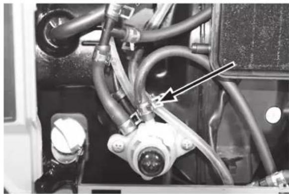
- Undo the maintenance cover screw (18) and remove the cover (19).
- Disconnect the fuel line leading to the primer.
- Open the petrol tap and empty the tank into a suitable container.
- Reconnect the fuel line.
- Refit the maintenance cover.
natural_image
Close-up of industrial piping and connectors with a black arrow pointing to a component (no visible text or symbols)Checking the cooling system
Check that the ventilation openings are clear. The ventilation openings supplying the air to the engine cooling system are located in several places on the generator, even on the bottom. The engine will overheat if any of the ventilation openings is blocked.
Checking the starting system
Undo the maintenance cover screw and remove the cover. Pull out the starter handle and inspect the starter cord for wear and other damage. Allow the starter cord to recoil slowly.
Cleaning the generator
Always store the generator in a cool and dry environment. The exterior of the generator can be cleaned with one or a combination of the following:
- A damp cloth
- A soft brush
- A vacuum cleaner
- Compressed air
Transportation
Note: Do not place anything on top of the generator whilst it is still hot from recent use. Before transporting or storing the generator for extended periods:
• Empty the fuel tank.
- Remove the spark plug cap from the spark plug.
- Keep the ventilation openings clear.
- Store the generator in a cool and dry environment.
Storage
Long-term storage of the generator will require some additional preventative measures to guard against deterioration and ensure that it works well when it is used again.
- Let the generator cool down. Empty the fuel system. Refer to the Emptying the fuel system section.
- Unscrew the spark plug and pour a tablespoonful of engine oil (10W-30 in the summer and 5W-30 in the winter) into the spark plug hole.
- Check the engine oil level and top-up the oil tank if necessary.
- Pull the starter handle a few times to distribute the oil in the cylinder, then refit the spark plug. Do NOT reconnect the spark plug cap.
- Pull the starter handle a few times until you feel a slight resistance, then slowly allow the starter cord to recoil.
- Clean the exterior of the generator.
- Store the generator indoors, in a dry and well-ventilated room. Do not cover the generator with a plastic sheet or dust cover. Non-porous covers will trap moisture around the generator and assist corrosion.
Warning:
If you choose to store the generator with fuel in the tank, consider the following advice:
- Do not store the generator in a room where there is any type of heater or appliance with a pilot light which could ignite petrol fumes. Also avoid any area containing spark-producing electric motors or where power tools are operated.
- Avoid storing the generator in areas with high humidity, because that promotes corrosion.
- Leave the engine switch/fuel cut-off valve in the 0 OFF position.
- Place the generator on a firm level surface. Tilting can cause the fuel to leak out.
When removing the generator from storage:
- Check the generator as described in section Preparations. Refuel with fresh petrol.
Responsible disposal
This symbol indicates that this product should not be disposed of with general household waste. This applies throughout the entire EU. In order to prevent any harm to the environment or health hazards caused by incorrect waste disposal, the product must be handed in for recycling so that the material can be disposed of in a responsible manner. When recycling your product, take it to your local collection facility or contact the place of purchase. They will ensure that the product is disposed of in an environmentally sound manner.

Troubleshooting guide
| Trouble Possible cause Action | |||||
| The engine does not start.Low engine output.The engine runs erratically. | Insufficient compression. | Loose spark plug. Tighten. | |||
| Loose cylinder head bolt. Tighten. | |||||
| Damaged cylinder head gasket. Replace gasket. | |||||
| Sufficient compression. | Fuel system problem: no fuel supplied to combustion chamber. | Choke not applied. Apply the choke. | |||
| Starter handle pulled too slowly. | Pull starter handle more sharply. | ||||
| Foreign matter in tank. Clean the tank. | |||||
| Clogged fuel line. Clean the fuel line. | |||||
| Fuel tank empty. Add fuel. | |||||
| Fuel cut-off valve or air vent closed. Open. | |||||
| Electrical system problem: fuel supplied to combustion chamber. | Insufficient spark. | Spark plug dirty or wet. | Clean. | ||
| Faulty spark plug. | Change spark plug. | ||||
| Faulty magnet. | Contact our customer services. | ||||
| Spark okay. | Carburettor set up wrong. | ||||
| Starter handle pulled too slowly. | Pull starter handle more sharply. | ||||
| Wrong type of fuel used. | Check. | ||||
| Overloading. | Check the rated power. | ||||
Specifications
Generator
Output voltage 230 V AC
Rated power 1.8 kW
Max power 2.0 kW
DC output 12 V DC, max 8.3 A
Engine
Model 160F
Type 1-cylinder, 4-stroke, OHC air-cooled petrol engine
Displacement 113 cc
Engine oil SAE 10W-30
Oil capacity 0.5 litres
Spark plug NGK CR7HSA (0.6–0.7 mm gap)
Other
Fuel Petrol min. 90 RON.
Fuel tank capacity 4.5 l
Sound power (LwA) 93 dB(A)
Starting system Magnapull
Dimensions 510 × 302 × 410 (L × W × H)
Weight 22 kg
Operating time Approx. 5 hours
Inverterelverk
Art.nr
40-8889
Modell
IG2400S
natural_image
Close-up of a mechanical component with a central knob and arrow indicator (no readable text or symbols)natural_image
Close-up of a fuel switch with ON/OFF labels (no readable text beyond 'FUEL' and symbols)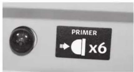
natural_image
Pure technical line drawing of electrical components without any text or symbolsLågeffektsläge
natural_image
Interior view of a vehicle's hood with visible electrical components and a black arrow pointing to a component (no text or symbols)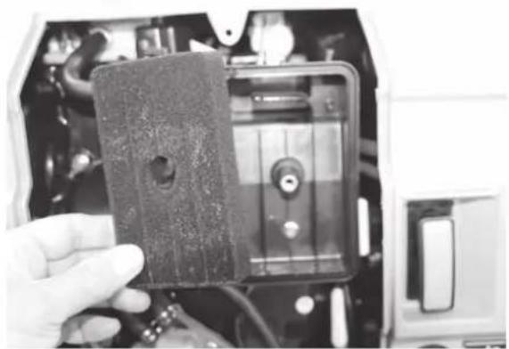
natural_image
Hand holding a dark textured object inside a vehicle's door frame, with no visible text or symbols.natural_image
Close-up of a Cocralt industrial machine casing with visible internal components and a black arrow pointing to a section (no text or symbols on the device itself)natural_image
Close-up of industrial piping and valves in a vehicle (no visible text or symbols)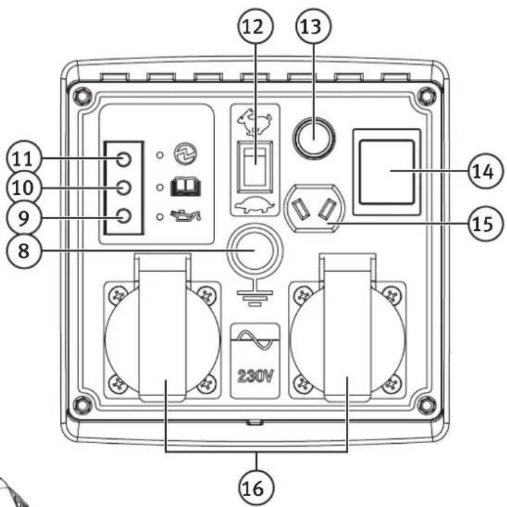
- Utluftingsventil for drivstofftank
- Lokk for drivstofftank
- Luftrenser med filter
- [START] Starthåndtak
- [FUEL, ON/OFF] Bensinkran på/av
- Avgassrør
- Oljepeilepinne/oljepåfylling
- Inngang for jordspyd
- Varsellampe for lavt oljenivå
- Varsellampe for overbelastning
- Indikatorlampe som viser at generatoren fungerer
- Effektmodusomkobler: – laveffektsmodus (ekstra lavt tomgangsmodus), – normaldrift
- Automatsikring for DC-utgang
- [ON/OFF] Motorbryter på/av
- DC-utgang 12 V DC
- 230 V AC-uttak
- [Choke, WARM-COLD] Choken er stengt i COLD-modus (kaldstart)
- Servicelukens läseskrue
- Serviceluke
- Primer
Bruk
Forberedelser
natural_image
Close-up of a mechanical component with a central knob and arrow indicator (no readable text or symbols)natural_image
Close-up of a fuel switch with ON/OFF labels (no readable text or symbols beyond control icons)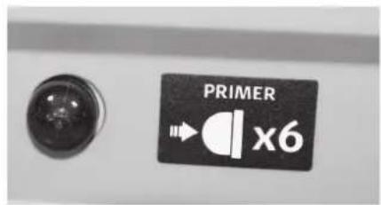
natural_image
Pure technical line drawing of electrical components without any text or symbolsLaveffektnivået
natural_image
Interior view of a vehicle's internal components, showing wiring, sensors, and a control panel (no text or symbols visible)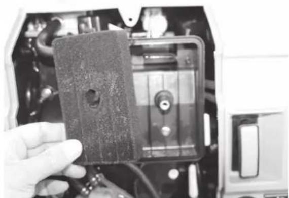
natural_image
Hand holding a black plastic electronic device with visible ports and components (no text or symbols)natural_image
Close-up of a Cocralt industrial device casing with visible internal components and mounting features (no text or symbols on body)natural_image
Close-up of mechanical components with hoses and connectors, no visible text or symbols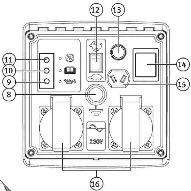
natural_image
Close-up of a mechanical component with a central knob and arrow indicator (no readable text or symbols)natural_image
Close-up of a fuel switch with ON/OFF labels (no readable text or symbols beyond control icons)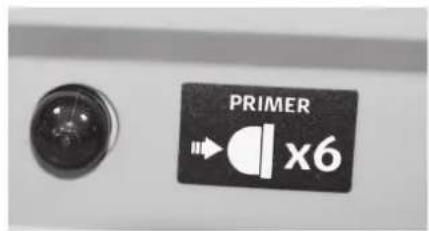
natural_image
Pure electrical circuit lines without any symbolsPienteho
natural_image
Interior view of a device showing internal components and wiring (no visible text or symbols)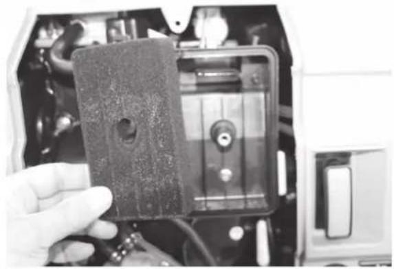
natural_image
Hand holding a black plastic device with a circular hole, partially enclosed in an open mechanical housing (no visible text or symbols)natural_image
Close-up of a Cocraft industrial device with a black arrow pointing to a seam or crack (no visible text or symbols on the device body)natural_image
Close-up of mechanical components with hoses and connectors, no visible text or symbols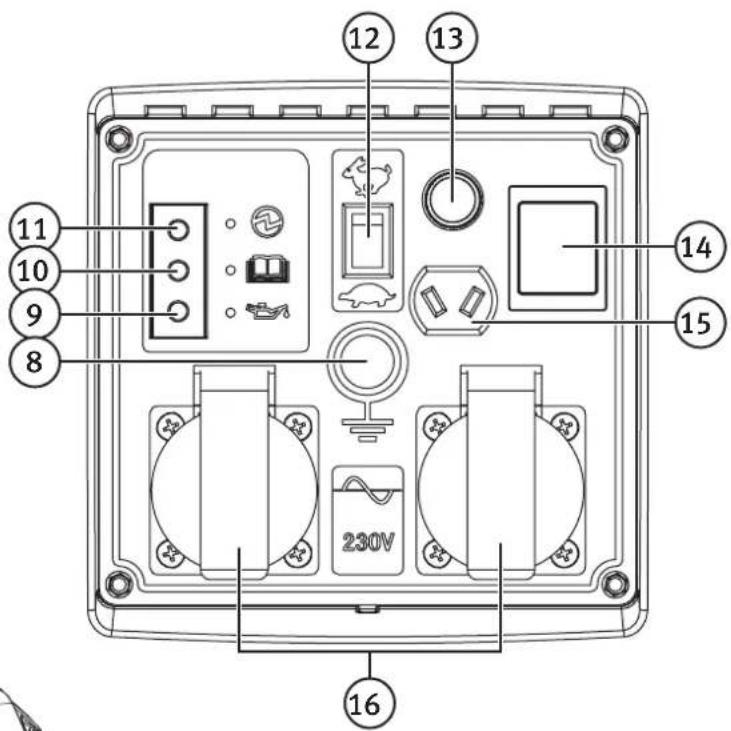
natural_image
Close-up of a mechanical component with a central knob and arrow indicator (no readable text or symbols)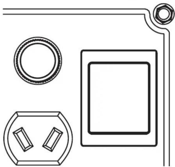
natural_image
Pure technical line drawing of electrical components without any text or symbolsnatural_image
Interior view of a vehicle's internal components, showing hoses, motors, and a control panel (no text or symbols visible)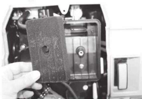
natural_image
Hand holding a small electronic device with visible ports and components (no text or symbols)natural_image
Close-up of a Cocralt industrial device casing with visible internal components and a black arrow pointing to a specific part (no text or symbols on the device itself)natural_image
Close-up of industrial piping and connectors with a black arrow pointing to a component (no visible text or symbols)Kühlung prüfen
Declaration of Conformity
Machinery Directive 2006/42/EC
EMC Directive 2014/30/EU
EN ISO 8528-13:2016
EN 60204-1:2006+A1:2009;
EN60204-1:2006/AC:2010
EN 55012:2007+A1
EN 61000-6-1:2007
EC type approval, no. e13*97/68SN3G2*2012/46*0772*00(II)
Issued by the following notified body:
10 - 13 Market Place
Kingston Upon Thames
Surrey
KT1 1JZ
Deutschland
Kundenservice
Hotline: 040 2999 78111
E-Mail: kundenservice@clasohlson.de
Homepage
www.clasohlson.de
Postanschrift
- Viktig information:
- Contents
- Safety....3
- Product description....4
- Operating instructions 6
- Connecting electrical devices 8
- Care and maintenance....9
- Storage 12
- Responsible disposal.... 12
- Specifications 13
- Safety
- Key to warning symbols
- Intended application
- Product description
- Operating instructions Preparations
- Check the oil level before switching the generator on
- Refuelling
- Starting the engine (cold start)
- △ Important:
- Economy mode
- Switching the engine off
- Connecting electrical devices
- Using the 230 V AC sockets
- Overload
- V DC socket for charging batteries
- Warning:
- Care and maintenance
- Maintenance schedule
- Caution!
- Engine oil
- Changing the oil
- Air filter
- Spark plug
- Emptying the fuel system
- Checking the cooling system
- Checking the starting system
- Cleaning the generator
- Transportation
- Storage
- Responsible disposal
- Specifications
- Generator
- Engine
- Other
- Inverterelverk
- Lågeffektsläge
- Bruk
- Forberedelser
- Laveffektnivået
- Pienteho
- Kühlung prüfen
- Declaration of Conformity
- Deutschland
Brand : Cocraft
Model : HI 2000
Category : Generator