
HPT 8 - Plane Cocraft - Free user manual and instructions
Find the device manual for free HPT 8 Cocraft in PDF.


| Product Type | Combination Surface and Thickness Planer |
| Brand | Cocraft |
| Model | HPT 8 |
| Rated Voltage | 230 V AC, 50 Hz |
| Power Consumption | 1250 W |
| No-Load Speed | 8000 RPM |
| Number of Planing Irons | 2 |
| Max Planing Width | 204 mm |
| Max Planing Height (Thickness) | 120 mm |
| Max Depth of Cut | 2 mm |
| Weight | 26 kg |
| Transport Dimensions (L x W x H) | 775 x 450 x 385 mm |
| Sound Pressure Level (LpA) | 86.7 dB(A) |
| Sound Power Level (LwA) | 99.7 dB(A) |
| Level Planing Table Size | 737 x 210 mm |
| Surface Planing Table Size | 254 x 215 mm |
| Angle Stop Adjustment Range | 45° to 90° |
| Dust Extraction Connection | Yes, with included extraction hood |
| Safety Features | Emergency stop, motor overload protection, cutter cover, locking levers |
| Maintenance | Regular lubrication of spindles, carbon brush inspection, blade sharpening/replacement |
| Included Accessories | Angle stop, extraction hood, crank, screws, Allen key |
| Minimum Workpiece Length | 250 mm |
| Minimum Workpiece Thickness | 5 mm |
Frequently Asked Questions - HPT 8 Cocraft
User questions about HPT 8 Cocraft
0 question about this device. Answer the ones you know or ask your own.
Ask a new question about this device
Download the instructions for your Plane in PDF format for free! Find your manual HPT 8 - Cocraft and take your electronic device back in hand. On this page are published all the documents necessary for the use of your device. HPT 8 by Cocraft.
USER MANUAL HPT 8 Cocraft
Read the entire instruction manual carefully and make sure that you fully understand it before you use the equipment. Keep the manual for future reference.
Viktig information:
Original instructions
Bruksanvisning i original
Originalbruksanvisning
Please read the entire instruction manual before use and save it for future reference. We reserve the right for any errors in text or images and for making any necessary technical changes to this document. If you should have any questions concerning technical problems please contact our Customer Services.
To think about
- Working with wood can be hazardous if carried out incorrectly!
- If you use the plane sensibly and carefully you will greatly reduce the risk of personal injury.
- Safety equipment in the form of protection, pushers, clamps, goggles, dust filters and hearing protection cannot compensate for poor judgement, carelessness or lack of attention!
- Remember: you are responsible for your own safety. The plane has been constructed for certain jobs. We strongly recommend that you do not alter the saw or use it for anything other than what it was designed for.
- DO NOT USE THE PLANE if you are not sure whether it can be used or ought to be used in the way you intended!
! Always remove the cable plug from the socket before servicing and adjusting the product!
General safety rules for yours and other's safety
Warning! When using electrical tools the following safety rules should always be followed in order to avoid risk of fire, electric shock and personal injury:
- Keep the working area clean. Cluttered surfaces and tables invite accidents.
- Do not use the tool in high risk environments. Electrical machines should not be used on damp or wet surfaces or in the rain. Make sure that the lighting is good in the workplace. Provide good ventilation during dusty jobs. Never use electrical machinery/tools where they may cause fire or explosion.
- Avoid electric shock. Avoid physical contact with earthed objects such as water mains, radiators, hobs etc. when using electrical machinery/tools.
- Keep children and visitors at a distance. All children and visitors should be kept at a safe distance from electrical machinery/tools or electric cables in the workplace.
- Keep the machinery childproof. Keep electrical machinery/tools locked away or out of reach of children when not in use.
- Do not push the machinery. It will carry out the work better and more safely at the intended feed rate.
- Use the correct tool. Do not push a tool or any other attachment to perform an operation which it is not designed for.
- Wear suitable attire. No loosely fitting clothes, gloves, necklaces, rings, bracelets or other jewellery which may get stuck in the rotating parts. Skid-proof shoes are recommended. Wear a hairnet (or equivalent) if you have long hair.
- Wear goggles. Always wear goggles, ordinary glasses are not suitable. Also use a dust filter or protective mask during dusty work.
- Use an extractor. Use an extractor to remove and collect dust and shavings, if the machine is designed for it; make sure the machine is used correctly and emptied when needed.
Warning: Dust and shavings from some wood types and wood products can damage your health even following a short period of exposure.
- Do not damage the electric cable. Never carry the machine by its electric cable. Do not pull the cable but instead pull out the plug when cutting off power. Make sure the cable does not come into contact with heat, oil or sharp edges.
- Secure work material properly. Use clamps or vices where possible, allowing you to manage the tool with both hands. It is safer than securing work material with one hand.
- Do not stretch yourself too far. Make sure that you adopt a secure and balanced posture the whole time.
- Keep the tools in trim. Make sure they are clean and that the edges are kept sharp for optimal effect and greater results. Follow the manual's recommendations for lubricating and changing parts. Check the electrical cable regularly; if damaged it should be replaced by qualified service technicians. Inspect all extension cables regularly so that they are not damaged. Make sure that the machine's/tool's handles and levers are dry, clean and free from oil, grease etc.
- Turning off the power. Pull out the plug and press emergency stop (if one exists) before service and replacement of attachments such as plane irons, drills, bits, emery cloth or knives.
- Remove all keys and service tools. Make a habit of checking that all keys and service tools are removed from the machine before turning on the power.
- Avoid accidental starts. Do not carry a tool with one finger on the power button if the cable is in the socket. Make sure that the power button is set to OFF when plugging in.
- Use correct extension cables. If you use extension cables outdoors, only use ones intended for outdoor use. Use extension cables with sufficient conductor lead area and unwind the entire cable.
- Use common sense and be careful. Think before carrying out a task so that you are able to carry it out correctly. Never use the machine/tool when you are tired, on medication etc.
- Check that all parts are undamaged. Check before starting up the tool: that all protective parts and other parts are undamaged and fulfil their function; that rotating parts rotate freely and are correctly aligned; that no moving parts can get stuck; that no defect or other factors have emerged that may hamper the work's performance. A cover or other part that is damaged should be repaired per part or be replaced. Damaged electrical cables and power switches should always be replaced by professionals. Never use the tool if you can not turn it on or off safely.
- Use recommended parts. Using non-recommended parts can cause accidents or risk personal injury.
- Repaired only by qualified technicians. The tool corresponds to current safety standards. Repairs on the tool should always be carried out by professionals using original reserve parts, otherwise the tool may cause accidents or risk for personal injury.
- Electrical tools should be connected to the mains via a circuit-breaker to insure personal safety! The product may not be changed or used for tasks it is not designed for! Regularly check that all screws and bolts are properly tightened!
Safety instructions for surface plane
- WARNING! Do not use the plane until it is completely assembled and connected according to the instructions in this manual.
- If you are not completely sure as to how a surface plane works: Ask a carpenter or other qualified person for advice.
- Insure that the electrical installation is carried out correctly. A qualified electrician must be employed for permanent connections. Only use earthed sockets.
- Perform all adjustments with the power switched off.
- Pull out electrical cable plugs before repairing.
- Never turn the power on before you have removed everything on the table (tools, waste, etc.).
- Make sure that the plane irons are sharp with no traces of rust or resin.
- Never plane without correctly mounted and adjusted protective covers.
- Do not place fingers near the cutter and plane's surface.
- Never place hand beneath the cutter when motor is running.
- Do not place fingers in front of shaving disposal vent. The cutter rotates incredibly fast.
- Never feed anything in from the outflow end.
• Always make sure work materials are properly secured. - When planing large materials: make sure that the material has table-high support when feeding and outflowing.
- Never start the plane when materials are touching the cutter.
- Check before planing that the material has no nails and other metal objects which could damage the plane irons.
- Make sure before starting that the plane irons are securely placed in the cutter according to the instructions in this manual.
• Always allow the cutter to reach full power before feeding in materials. - If during planing the plane shows any likelihood of tipping, sliding around or begins to move off its base: stop planing and securely screw the plane to the base.
- Do not plane objects that are shorter than 250 mm, narrower than 19 mm, wider than 204 mm or thinner than 5 mm.
- Make sure that work surfaces are tidy before leaving the plane.
- Switch power to OFF and pull out electrical cable plugs from the socket if there is something missing from the plane or if something is damaged; likewise if something in the electrical system is not working properly. Replace faulty or damaged parts before planing again.
- Adjust the cutter cover so that it covers the whole cutter apart from the material being planed.
Special warning instructions for this model
- Check regularly that the plane irons and iron holders are securely in place in the cutter.
- The maximum protrusion allowed for irons' cutting edge outside the cutter: 1 mm (± 10 %).
- Never remove anything from the machine's cover, other than for servicing.
- Set in place the covers and secure them before starting the machine.
- Connect a shavings extractor to the extraction hood on the plane.
- The machine should only be connected to an earthed socket.
- Check regularly that the reverse gear locks are clean and moveable.
• Always wear protective goggles. - Never take an edge larger than 2 mm.
Unpacking and delivery checks
Carefully remove the plane and all loose parts from the package.
The package contains
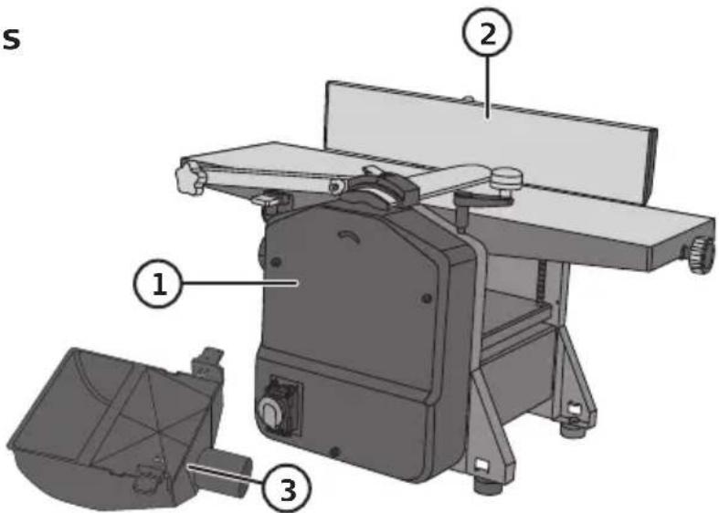
- Surface plane
- Angle stop
-
Extraction hood
-
Crank
- Screws (M5 × 15)
- Locking washer 5 mm
- Plane washer 5 mm
- Allen key (4 mm)
Product marking with safety symbols on the machine

Read all instructions for use.

Always use hearing protection.

Always use goggles or visors and a respirator.
Product marking with warning text on the machine
Warning! Rotating cutter, keep hands out of the way.
- Read all instructions and try to understand the machine's operations.
- Do not use the machine if the covers are not mounted, correctly adjusted and without fault.
- Never perform larger cuts than 2 mm.
- Never plane material shorter than 250 mm
- Do not expose the machine to damp or rain.
- Only plain one object at a time to avoid objects jutting backwards.
Use
Warning! Always pull out electrical cable plugs from the socket before servicing and adjusting the plane irons, cutting depth and other settings.
Mounting the angle stop
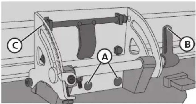
- Screw tight the stop on the side of the outflow table with two screws (A).
- Set desired angle: Open the locking lever (B) and set desired angle on the shell (C), tighten locking lever.
Mounting the extraction hood
Attention! For your safety the extraction hood must always be mounted when both level and surface planing; and both locking levers (H) must be pressed in order for the motor to start.
When planing, the extraction hood (E) must be mounted as it acts as a cover!
-
Move the object sideways:
-
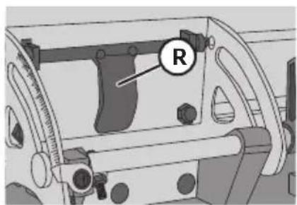
Fold down the locking bridge (R) and move the stop sideways.
- Securely lock the stop by pressing the locking bridge (R) upwards.
-
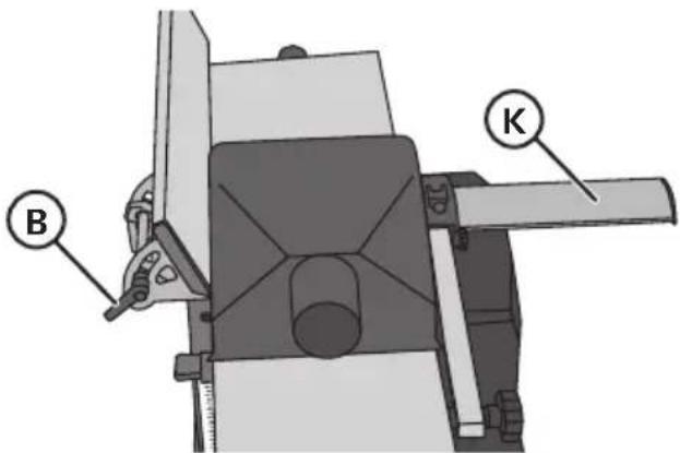
Open the locking lever (B) and angle the stop slightly.
-
Pull both locking levers (H) on the extraction hood (E).
- Lay the hood (E) on the levelling table so that the locking levers (H) fit the vents in the levelling table (G); push in the locking levers.
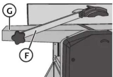
- Loosen the arm (F) holding the cutter cover (K) and unfold it; pull the cutter cover to the side.
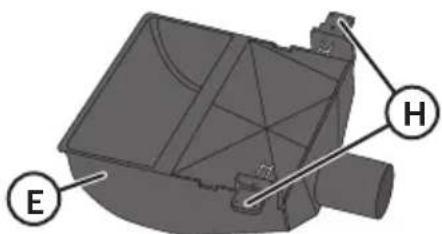
When level planing, the extraction hood (E) must be mounted as it acts as a cover!
- Lower the table as far as it can.
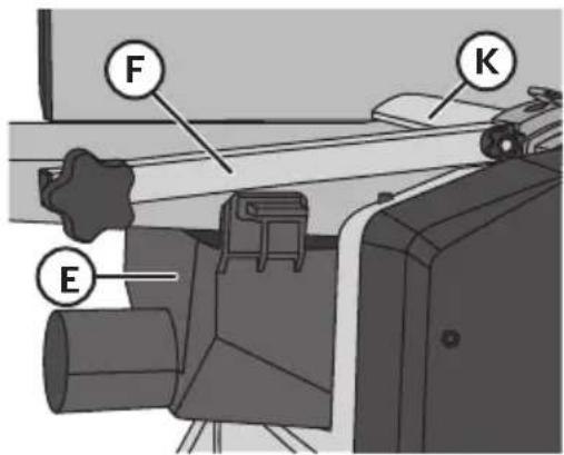
- Loosen the arm (F) holding the cutter cover (K) and unfold it.
- Pull both locking levers (H) on the extraction hood.
- Push in the extraction hood under the levelling table so that the locking levers (H) fit the vents in the levelling table (G); push in the locking levers (H).
Setting cutter cover
- Loosen the locking wheel holding the arm (F) and lift to the correct height (the material's thickness); tighten the locking wheel.
- Press the cover against the material so that it covers the cutter's free parts, or place above the material if it is wide.
- Tighten the cover's locking wheel.
Level planing
- Mounting the extraction hood.
- Set the desired cutting depth with the wheel (L); settings of the feeding table (N) are shown on the shell (M) (clockwise = decrease, counter-clockwise = increase).
- Cutting depth of 0.5–1.5 mm provides the best surface. Warning! Position the cutter cover so that it covers the cutter's free parts.
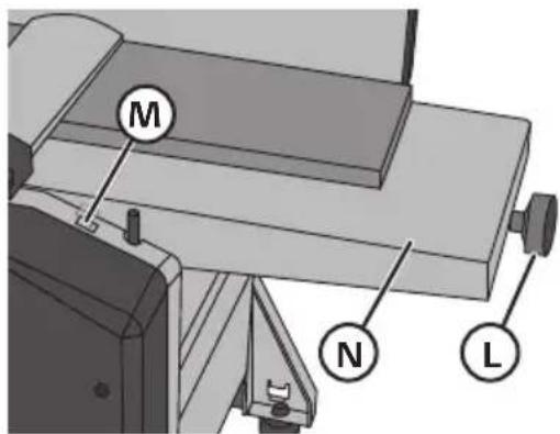
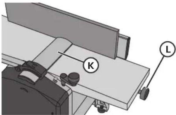
- Press the board against the feeding table and position the cutter cover at the same height as the left hand (the board should easily go through the gap). Start the motor and let it rev up then slowly and carefully feed the board through over the cutter. Allow hands to move over the cutter cover.
Surface planing
- Mount the extraction hood (E) above the levelling table.
- Set desired dimension for the material with the crank (O) (1 turn = 3 mm), feed the material's thickness and set the planing thickness 1–2 mm less and make the first plane cut.
- Start the motor and let it rev up then slowly and carefully feed onto the planing table with the level planing side facing downwards.
- Slowly push the board inwards until the feeding roller grips the board. If the board is wedge-shaped put the thicker end in first.
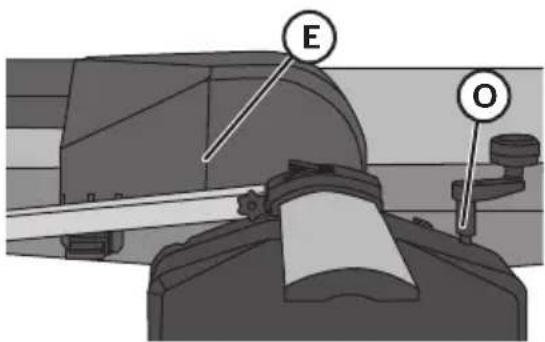
Warning! Never plane short material, feed in narrow materials in the middle of the width of the cutter. Make sure the cable moves freely and does not get tangled in the cutter.
Changing planing irons
- Planing irons can be sharpened (HSS) up to three times (3 × 0.05 mm):
- Remove the angle stop and lift up the arm holding the cover.
- Turn the cutter by hand until one of the iron's tightening screws is visibly turned upwards.
- Loosen the four screws on the steel holder (which press the planing iron against the cutter) with the accompanying Allen keys.
- Remove the planing iron and steel holder out of the slot on the cutter. With an oiled cloth, clean the steel holder, slot and planing iron, removing waste, shavings and dust.
- Sharpen the planing iron or change it. Put the planing iron and steel holder in the slot again and lock them in place by turning the tightening screws clockwise (but do not tighten fully), make sure the planing iron is lying against the cutter allowing the two adjusting screws to fit into their notch in the planing iron.
- Adjust the edges sticking out with the accompanying 4 mm Allen keys by turning the steel holder's two adjusting screws in and out according to requirement. After setting correctly, tighten the fastening screws again.
- Check how much cutter steel sticks out above the outflow table with a template or ruler on the outflow table. The maximum protrusion over the outflow table is: 0.1 mm. (measure several times over the width of the whole planing blade).
- Tighten the screws and measure the edges sticking out again after tightening. Attention! Do not use a key with a longer shaft than the one delivered.
- Repeat the procedure with the other planing iron, then check that both planing irons stick out the same amount.
Raising and lowering planing table
Take out the crank and mount it on the axle on the above side of the plane, turn the crank until it goes down and locks tightly on the axle; remove after setting.
Mounting the planer/thickesser on a bench etc.
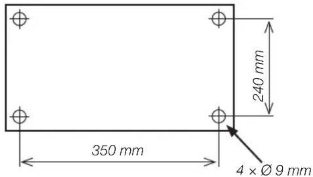
The level and surface plane should be mounted on a stable bench, table etc. The plane weighs 26 kg and should be fastened to a hard, flat surface. It has four fastening holes ( 9 mm). Fasten the plane with M8 bolts, washers and locking bolts (not included).
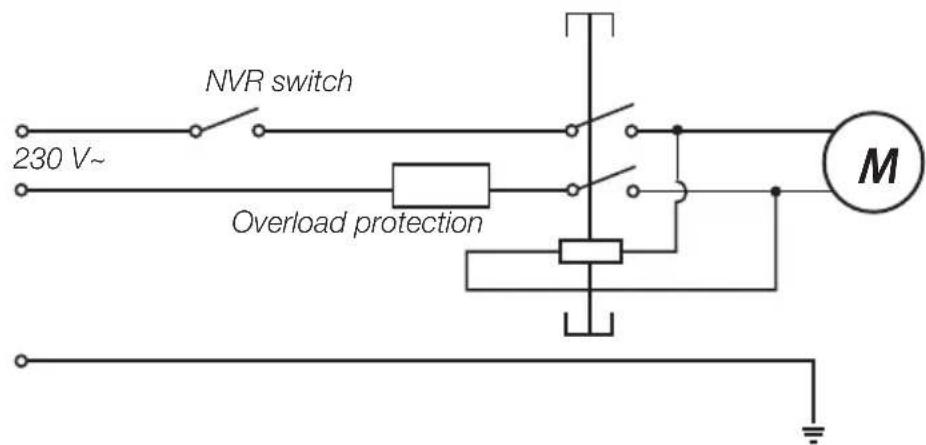
Wiring diagram
Motor cover
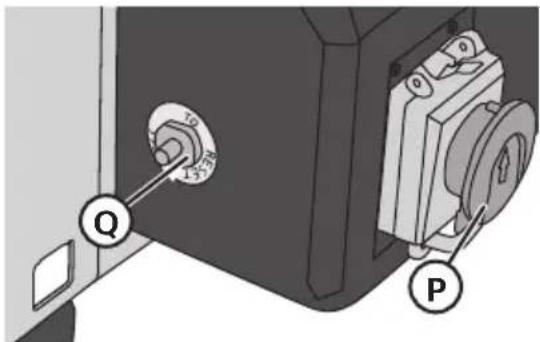
The plane is equipped with a motor cover which is triggered automatically and in that way stops the plane if the motor overheats due to overloading. The motor cover can only be reset by hand after the motor has cooled down. Let it stand for 15–30 minutes. The motor cover sits on one end near the emergency stop.
If you believe the motor cover has been released do as follows:
- Press the emergency stop (P).
- Raise the cutter and remove the material being planed.
- Wait for 15–30 minutes until the motor has cooled down.
- Press the reset button (Q).
- Try starting the motor again.
Tips for use
- Read the warning text carefully before using the plane.
- Fasten the plane onto a stable base at a good height.
- Set desired planing height with the crank and the extraction hose.
- Plug into wall socket.
- Press the green button (1) on the power switch to start the motor.
- Test-run the plane on a piece of board. Measure the result and adjust according to requirement.
- Use the roll support if the work material is long.
- Turn the plane off: Press (0) the power switch, press emergency stop and pull out the plug when the operation is finished.
- Tidy the workplace.
Care
Inspection and changing of carbon brushes
Attention! Press the emergency stop and pull out the electrical cable plug before inspecting the carbon brushes.
- Regularly check the carbon brushes and change them if the length is below 5 mm.
- Change the carbon brushes in pairs.
- Keep the carbon brushes clean and make sure they can move freely in the carbon holder.
Cleaning
Always brush away dirt, shavings and foreign objects on feeding rollers and in ventilation holes and cables. Make sure that oil or water does not get into the motor.
Greasing
Grease the four spindles on the planing table regularly with lubricant (WD 40, 556 etc.) to prevent them from drying out.
Responsible disposal
This symbol indicates that this product should not be disposed of with general household waste. This applies throughout the entire EU. In order to prevent any harm to the environment or health hazards caused by incorrect waste disposal, the product must be handed in for recycling so that the material can be disposed of in a responsible manner. When recycling your product, take it to your local collection facility or contact the place of purchase. They will ensure that the product is disposed of in an environmentally sound manner.
natural_image
Symbol of a trash bin crossed with no text or numbers, representing waste sorting or disposal (no text present)Specifications
Rated voltage 230 VAC, 50 Hz
Effect 1250 W
No. plane irons 2
Number of revolutions 8000 RPM
Weight 26 kg
Table size 330 × 235 mm
Size, total 775 × 450 × 385 (in transit)
Sound level LpA 86.7 dB(A)
Sound level LwA 99.7 dB(A)
Level plane
Max planing width 204 mm
Object, size 540 × 100 mm
Table, size 737 × 210 mm
Angle adjustment 45–90°
Max shaving thickness 2 mm
Surface plane
Max plane width 204 mm
Max planing height 120 mm
Max shaving thickness 2 mm
Table, size 254 × 215 mm
Rikt & Planhyvel
Art.nr 18-3029 Modell MBY8
30-9131 MBY8
Montera utsugskåpan
natural_image
3D mechanical component diagram with labeled points E and H (no text or symbols beyond labels)Användningstips
Produktmerking med sikkerhetssymboler på maskinen

Les hele bruksanvisningen.

Monter avsugsdekselet
natural_image
Mechanical assembly diagram showing a machine with labeled components K and L (no text or symbols beyond labels)Brukertips
natural_image
Symbol of a trash bin crossed with no text or labels, accompanied by a solid black rectangle below (no text or symbols present)Spesifikasjoner
Spenning 230 V AC, 50 Hz
Effekt 1250 W
Antall høvelstål 2 stk.
Turtall 8000 o/min
Vekt 26 kg
natural_image
3D mechanical component diagram with labeled points E and H (no text or symbols beyond labels)natural_image
Symbol of a trash bin crossed with no text or labels, accompanied by a blank rectangular block below (no text or symbols present)Tekniset tiedot
Nimellisjännite 230 VAC, 50 Hz, 5,8 A
Teho 1250 W
natural_image
Mechanical component diagram showing a housing with labeled part 'R' (no text or symbols beyond label)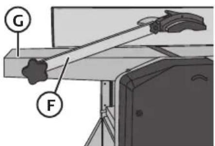
natural_image
3D mechanical component diagram with labeled points E and H (no text or symbols beyond labels)natural_image
Mechanical assembly diagram showing a workbench with labeled components K and L (no text or symbols beyond labels)natural_image
Symbol of a trash bin with crossed lines indicating no waste or restriction, and a solid black rectangle below (no text or labels)Technische Daten
Declaration of Conformity
Declares that this product complies with the requirements of the following directives and standards
Manager Technique & Quality
Insjön, Sweden, 2016-12-01
Sverige
Postal 10 - 13 Market Place
Kingston Upon Thames
Surrey
KT1 1JZ
Deutschland
Kundenservice Hotline: 040 2999 78111
E-Mail: kundenservice@clasohlson.de
Homepage
www.clasohlson.de
- Viktig information:
- To think about
- General safety rules for yours and other's safety
- Safety instructions for surface plane
- Special warning instructions for this model
- Unpacking and delivery checks
- The package contains
- Product marking with safety symbols on the machine
- Product marking with warning text on the machine
- Use
- Mounting the angle stop
- Mounting the extraction hood
- When level planing, the extraction hood (E) must be mounted as it acts as a cover!
- Setting cutter cover
- Level planing
- Surface planing
- Changing planing irons
- Raising and lowering planing table
- Mounting the planer/thickesser on a bench etc.
- Wiring diagram
- Motor cover
- Tips for use
- Care
- Inspection and changing of carbon brushes
- Cleaning
- Greasing
- Responsible disposal
- Specifications
- Level plane
- Surface plane
- Rikt & Planhyvel
- Montera utsugskåpan
- Användningstips
- Produktmerking med sikkerhetssymboler på maskinen
- Monter avsugsdekselet
- Brukertips
- Spesifikasjoner
- Tekniset tiedot
- Technische Daten
- Declaration of Conformity
- Sverige
- Deutschland
Brand : Cocraft
Model : HPT 8
Category : Plane