
Euroline KEA 1000 - Receiver KATHREIN - Free user manual and instructions
Find the device manual for free Euroline KEA 1000 KATHREIN in PDF.

| Product Type | Satellite Receiver |
| Brand | Kathrein |
| Model | Euroline KEA 1000 |
| Dimensions (W x H x D) | Approx. 260 x 45 x 160 mm |
| Weight | Approx. 0.5 kg |
| Power Supply | 12V DC, 1A (external power adapter) |
| Power Consumption | < 10 W |
| Input Frequency | 950 - 2150 MHz |
| Input Level | -65 to -25 dBm |
| Demodulation | DVB-S, DVB-S2 |
| Symbol Rate | 2 - 45 MS/s |
| Video Output | SCART, Composite, S-Video |
| Audio Output | Stereo RCA, Digital Audio (S/PDIF) |
| Channel Memory | 2000 channels |
| DiSEqC Support | DiSEqC 1.0, 1.2, 1.3 (USALS) |
| Main Functions | Satellite TV reception, channel list management, favorite lists, parental lock, software update via satellite |
| Remote Control | Included |
| Maintenance & Cleaning | Clean with a soft, dry cloth. Do not use liquids or abrasives. |
| Safety | Keep away from moisture, heat sources, and direct sunlight. Use only the provided power adapter. |
| Spare Parts & Reparability | Spare parts (remote control, power adapter) available through service. Repairs should be carried out by authorized personnel. |
Frequently Asked Questions - Euroline KEA 1000 KATHREIN
User questions about Euroline KEA 1000 KATHREIN
0 question about this device. Answer the ones you know or ask your own.
Ask a new question about this device
Download the instructions for your Receiver in PDF format for free! Find your manual Euroline KEA 1000 - KATHREIN and take your electronic device back in hand. On this page are published all the documents necessary for the use of your device. Euroline KEA 1000 by KATHREIN.
USER MANUAL Euroline KEA 1000 KATHREIN
natural_image
Technical line drawing of a mechanical clamp or bracket assembly (no text or symbols)Sicherheitshinweise
natural_image
Technical line drawing of a mechanical device with two views: one showing a clamp mechanism and the other showing a cylindrical component (no text or symbols present)natural_image
Diagram of two satellites with solar panels and a central body, no text or symbols presentnatural_image
Diagram of a mechanical clamp or clamping device with numbered parts, no text or symbols presentnatural_image
Technical illustration of a mechanical clamp or bracket assembly with three views showing internal components and alignment (no text or symbols)natural_image
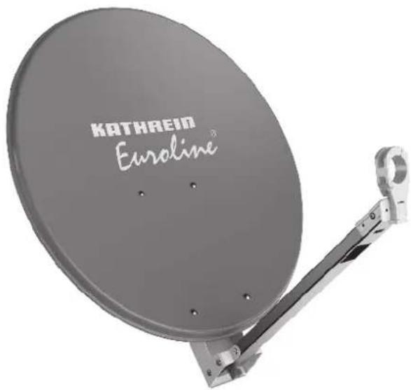
Technical illustration of a mechanical clamp or bracket assembly with circular components and internal components, shown in two views (no text or symbols present)■ Aluminium reflector, powder-coated
■ Back of galvanised sheet steel
■ LNB carrier arm of aluminium
■ Galvanised steel mast clamps and threaded clamps (completely pre-mounted)
■ Nuts and bolts in stainless steel
Colours: KEA 650/750/850/1000 – graphite (similar to RAL 7012), red brown (similar to RAL 8012), white (similar to RAL 9002)
■ Items supplied: reflector with pre-mounted mast and feed system support
■ Only possible for KEA 750/850: For mounting two LNBs on the boom (multifeed reception) to receive the signals of satellites up to 6° apart (e.g. ASTRA/EUTELSAT HOTBIRD). The KEZ 02 multifeed bracket (order no. 20010056) is additionally required (see Accessories (Optional, Not Included), p. 2).
Intended Use
The parabolic antennas are intended solely for the reception of satellite signals and for use only as domestic antennas. DIN EN 60728-11 specifies that a domestic antenna should have no more than 6 m free mast length and a fixed-end moment up to 1650 Nm.
The parabolic antennas are designed for use with a feed system (LNB) for reception of the signals from one satellite position, or two feed systems for multifeed applications for reception of the signals from two satellite positions with up to 6° satellite spacing (in case of KEA 750/850/1000, with KEZ 02).
- It is unsuitable for mounting on structures that are liable to vibration.
- Make sure to comply with the values for the maximum wind load listed in the Technical Data. If this load is exceeded, parts could break away!
- The feed systems and instructions for their installation are not included in the scope of supply of the parabolic antenna.
- Do not use the parabolic antenna for purposes other than those listed in this manual! In particular, never
– modify any of its components or - fit any components other than those expressly intended by the manufacturer for use with the antenna.
Non-compliance may lead to the antenna no longer being sufficiently stable and safe! - The laws and standards currently valid for the installation and operation of the antenna are binding and are to be observed and
applied without fail!
Any use other than that specified or failure to observe these application notes will invalidate the warranty or guarantee.
Tip
Keep these instructions for further reference and pass them on to the next owner of the antenna..
Scope of Delivery
Scope of delivery KEA 650/750: Scope of delivery KEA 850/1000:
• pre-mounted support arm
- reflector
- 4 x M6 x 35 Inox screws
- 4 x M6 inox self-locking nuts
- Instructions for Use
• pre-mounted support arm
- reflector
- 6 x M6 x 35 Inox screws
- 6 x M6 inox self-locking nuts
- instructions for use
Accessories (Optional, Not Included)
■ Multifeed bracket KEZ 02, order no. 20010056
Tip
Multifeed bracket suitable for KEA 750/850. To determine the elevation values for your location, consult the azimuth/elevation calculation table under http://www.kathrein-ds.com.
natural_image
Technical line drawing of a mechanical clamp or bracket assembly (no text or symbols)Safety Instructions
Make sure that you read and observe the instructions in this manual before you install, connect or use the parabolic antenna! If you disregard these instructions,
- malfunctions may arise, creating risks to your life and health,
• defects in the installation or the connection may cause damage to the antenna or to the attachment point, - the manufacturer will not accept liability for malfunctions and damage arising!
DANGER
Danger to life caused by electric shock when touching electrical installations!
▶ Do not install antennas in the vicinity of overhead power cables.
▶ Maintain a minimum clearance of 1 m from all electrical devices.
▶ Never work on antenna systems during a thunderstorm or when a thunderstorm is approaching.

WARNING
Risk of severe injury during installation on the roof!
▶ Wear stable shoes with non-slip soles.
Do not go on to roofs or other high places without a correctly attached safety harness that is in good condition. Otherwise use a work platform.
▶ Make sure that the roof and climbing aid are dry, clean and non-slip.
Make sure that the person carrying out the installation or repair has a secure position to stand and hold on whilst working. If necessary, wear a roof safety harness.
▶ Make sure that the person carrying out the installation or repair work does not suffer from vertigo and can move around on the roof safely.
▶ Make sure that the roof is able to bear your weight. Never walk on fragile or unstable surfaces! In case of doubt, contact a qualified specialist dealer or specialist roofing contractor to find an appropriate installation location.
▶ Make sure that there is nobody underneath the antenna during installation, repairs or dismantling.
▶ Make sure to comply with the respective national safety regulations and current standards such as DIN EN 60728-11.
WARNING
Risk of fire with risk of severe injury due to atmospheric over-voltages (static charges) or lightning discharges (e.g. during thunderstorms)!
Never install antennas on buildings with easily flammable roof coverings such as straw or thatched roofs.
Selecting the Installation Site
It is essential to select the correct installation site. This determines whether the parabolic antenna can be erected safely and perform to its optimum capabilities. When selecting the installation site, take account of the following:
- The special features of the structure of the building. If the installation is at the edge of the roof or the building or on a cylindrical structure, DIN EN 1991-1-4 and DIN 4131 specify the increased wind and vibration loadings that should be allowed for.
- The dynamic properties of the antenna and the structure can interact and cause detrimental changes.
- Failure to comply with the afore mentioned may lead to the maximum load or vibration fatigue stress listed in the Technical Data being exceeded.
Tip
The parabolic antenna need not necessarily be mounted on the roof, since the requirement is not height as such but an unobstructed "view" of the satellite. For this reason, an appropriate installation site might also be found for instance in the garden, on the terrace, on the face of the building or on a garage.
If you have other alternatives, do not install the antenna on a roof. Installation at alternative sites will be much easier and faster and reduce the hazards associated with installation work on the roof!
For good reception, an unobstructed "view" to the south ( ±20^ ) must be ensured, at an elevation of about 30^ . The following satellites are then available for selection:
1 TÜRKSAT 3) 42° East 5 EUTELSAT W 2 16° East
2 ASTRA 2 group 28.2° East 6 EUTELSAT HOTBIRD 13° East
3 ASTRA 3 group 23.5° East 7 EUTELSAT W 1 10° East
4 ASTRA 1 group 19.2° East 8 HISPASAT 30° West
Make sure that there are no obstacles between the parabolic antenna and the respective satellite (e.g. trees, roofs, house eaves or other antennas). Such items or structures can impair reception to the extent that during unfavourable stormy weather no signals are received altogether.
^7 The reception is dependent upon the respective location and the satellite coverage zone
Installing the Antenna
When installing the antenna carrier (mast or wall boom), ensure that it is standing upright. Otherwise, there may be problems with the alignment of the antenna to the satellites.
Requirements for the Antenna Carrier
- Use only masts or support tubes that are specially designed for installation of antennas. Other tubes generally do not have the strength required to withstand the forces of wind and weather.
- For mast installation, select a tube diameter between 30 and 90 mm with a wall thickness at least 2 mm. For wall installation, we recommend the use of Kathrein ZAS 60 or ZAS 61 wall brackets.
- For mast installation on a roof, the mast must be clamped for at least 1/6 of its free length (in the example bottom right this is 0.7 m).
Several antennas on a single antenna carrier:
- Install the parabolic antenna as far down the mast as possible, so as to minimise the bending moment at the clamping point.
- Under no circumstances exceed the maximum value for the loading on the mast or mast support, as stated in the Technical Data. The maximum loading will not be exceeded if you arrange your antenna system as shown in the example bottom right, and use conventional domestic antennas together with mast components from a specialist supplier (tube in steel grade S 355 (St 52) with an outer diameter of 60 mm and a wall thickness of 2.5 mm at the mast clamping point – e.g. Kathrein ZSH 59).
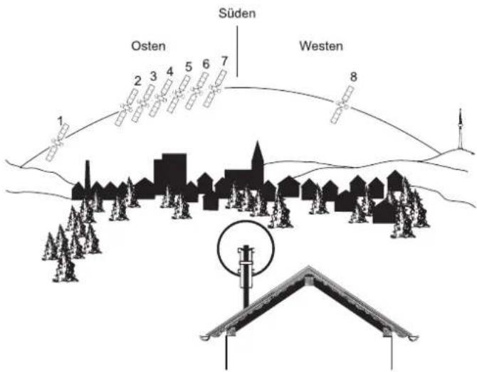
Fig. 1: Selecting installation site
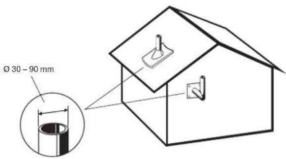
Fig. 2: Selecting antenna carrier
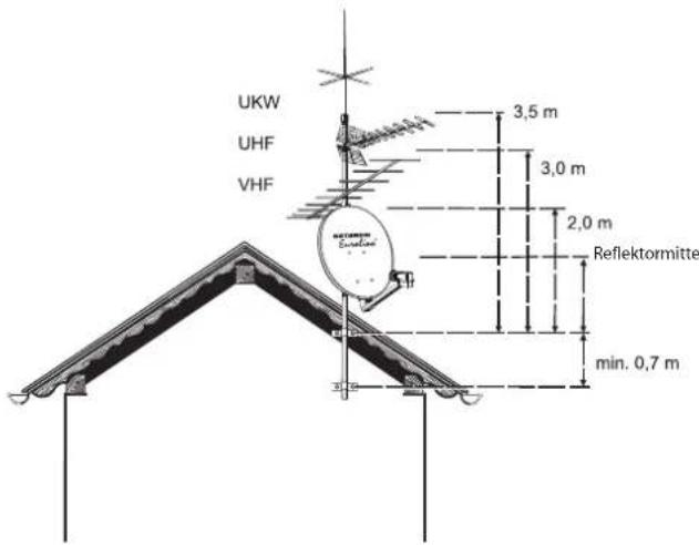
Fig. 3: Several antennas on a single antenna carrier

Notice
If you arrange the structure differently, you must calculate wind loading and bending moment at the clamping point as specified in DIN EN 60728-11 (or have a specialist do the calculation for you).
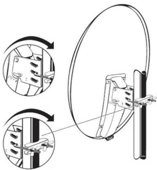
Installing the Reflector
- Fold down the feed arm and screw it on using the star knob
(Fig. 4).
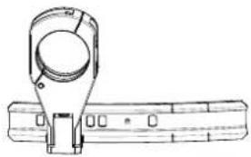
Installing the Mast Clamps
- Loosen the winged nuts and bring the threaded U-bolt and threaded clamp into installation position (Fig. 4).
- Attach the parabolic reflector to the mast or boom, at first loosely. Later on, the parabolic reflector will have to be aligned with respect to the azimuth.
- Tighten the screw connectors between mast clamp and antenna support finger-tight, loosen if required. Later on, the parabolic reflector will have to be aligned with respect to the elevation angle.
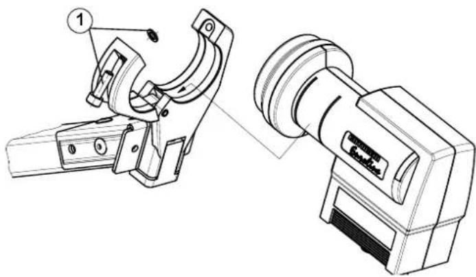
Installing the Feed System Support
- Fold open the feed system support.
- Insert the feed system.
- Close the feed system support and tighten the screw slightly. The feed system may need to be set to the polarisation. Refer to the instructions for use of the feed system.
Feed System (LNB)
The feed system(s) and instructions for their installation are not included in the scope of supply of the parabolic antenna.
For more detailed information on their correct installation, refer to the manuals supplied with the respective feed system.
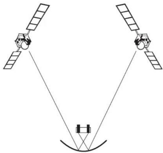
Example for the installation positions for a multifeed application with up to 6° satellite spacing using the multifeed bracket KEZ 02 (only possible with KEA 750/850/1000):
Pos. 1 Pos. 2
ASTRA 19.2° East EUTELSAT 13° East
EUTELSAT 16° East EUTELSAT 10° East
EUTELSAT 13° East EUTELSAT 7° East
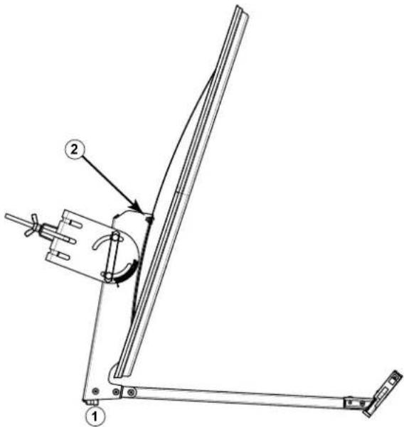
Fig. 4: Installing the reflector
natural_image
Technical line drawing of a mechanical device with two views: top shows a clamp mechanism, bottom shows a pulley device (no text or symbols present)Fig. 5: Installing the feed system support
natural_image
Diagram of two satellites with antennas and a central body, no text or symbols presentFig. 6: Aligning the antenna towards the satellites
Aligning the Antenna
The antenna must be exactly aligned towards the satellite in respect of both the direction (azimuth) and also the inclination (elevation). For multi-feed applications, the antenna should be aligned towards the satellite which is transmitting the weakest signal.
Setting the Inclination (Elevation)
- When adjusting the inclination (elevation), observe the scaling on the right side of the mast fixing, as seen from
- Loosen both screws on each side of the mast fixing to
- Adjust the inclination (elevation) in accordance with the arrow.
Tip
You will find the exact elevation angle for your location in the azimuth/elevation table at the end of this manual. If your location is not listed in this table, use the nearest listed location as your reference.
- Hand-tighten the two screws on the mast fixing. Fine adjustment of the elevation must be carried out later, see Fine Adjustment, p. 6.
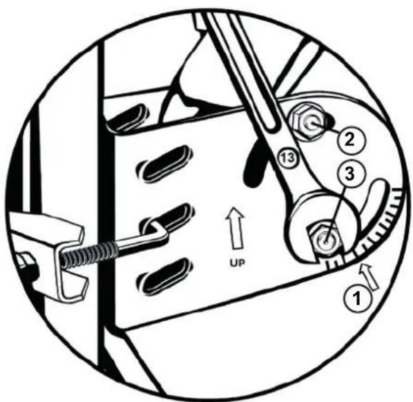
Fig. 7: Setting the Inclination (elevation)
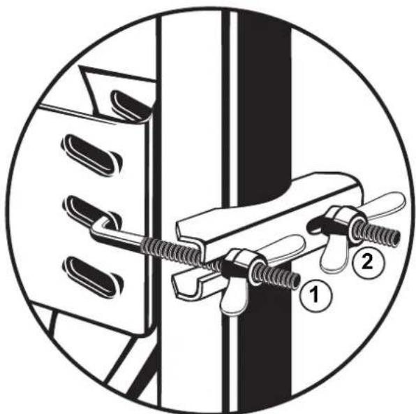
Setting the Direction (Azimuth)
Tip
If you yourself are unable whilst performing the adjustments to read the results of the alignment work on an antenna meter or screen connected to the satellite receiver, you may need an assistant for the following steps. The precise alignment of the antenna can be achieved only if a digital antenna meter is used. Ask your dealer about this.
- Set the satellite receiver to a known channel so that you can check that you have really "locked on" to the desired satellite.
- Twist the antenna so that it faces roughly south.
- Slowly twist the antenna about its central axis to the left and right until the best reception is obtained for the selected channel.
- Tighten the wing nuts just enough to prevent the antenna turning.
natural_image
Diagram of a mechanical clamp or clamping device with numbered parts, no text or symbols presentFig. 8: Setting the Direction (azimuth)
Fine Adjustment
- Loosen the screws on each side of the mast fixing.
- Swivel the antenna slightly upwards and downwards until you either measure the strongest antenna signal on your
antenna meter or until you visualise the best image quality on your screen. To do this, swivel the antenna far enough upwards and downwards until you get to the limits when the first "little blocks" (digital) appear on the screen.
-
Position the antenna midway between these two points.
-
Alternate correcting the direction (azimuth) and inclination (elevation) until the measured results or the picture quality show no further improvement.
Tip
When tightening the nuts on the clamp, there is a risk of the antenna turning slightly. Bear this in mind while performing the fine adjustment and use it for the precise adjustment.
Finally Tightening of the Antenna
- Tighten the nuts on the bracket using your hand.
- Use an open-ended spanner (AF 10 or 13 mm) to tighten up each of the wing nuts one turn.
For KEA 650 and KEA 750:
- Tighten the screws left and right of the bracket on the inclination scale (torque spanner: 7 - 10 Nm).
For KEA 850 and KEA 1000:
-
Tighten both screws on each side of the mast fixing (torque spanner: 7 - 10 Nm).
-
Make sure that all screws are tightened.
-
Insert the cables in the opening on the bottom of the boom and fasten them so that they are not damaged because of chafing caused by wind.
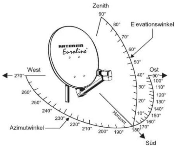
Fig. 9: Fine adjustment
natural_image
Technical illustration of a mechanical clamp or bracket assembly with three views (top, front, side), showing structural details without any text or symbols.Fig. 10: Final tightening of the antenna (KEA 650 and KEA 750)

natural_image
Technical illustration of a mechanical clamp or bracket assembly with circular components and internal components, shown in two views (no text or symbols present)Fig. 11: Final tightening of the antenna (KEA 850 and KEA 1000)
Antenna earthing / lightning protection

WARNING
Risk of severe injury and/or material damage due to lightning strike, electrostatic charge or short circuit!
▶ Make sure that grounding and lightning protection work is only performed by specially trained electricians.
▶ Never perform grounding and lightning protection work if you are not a specialist with the appropriate knowledge.
▶ An equipotential bonding conductor of 4.4 mm ^2 should be provided.
▶ Connect the cable shields of all coaxial antenna downlink cables to the mast using an equipotential bonding cable.

Notice
The instructions printed here are not an invitation to nonspecialists to perform grounding and lightning protection work on their own account.
- Erect and ground the antenna specified in standard DIN EN 60728-11. Grounding is not required for antennas which are installed
- more than 2 m below the edge of the roof and - at the same time less than 1.5 m away from buildings.
- For grounding, connect the mast by means of a suitable ground conductor to the lightning protection system of the building, using the shortest route. If no lightning protection system is available, connect it to the building ground conductor.
- Connections to the lightning protection system may only be made by a specialist qualified in lightning protection system installations.
Suitable as ground conductors is
a single solid wire with a cross-section of at least 16 mm ^2 copper, at least 25 mm ^2 aluminium or at least 50 mm ^2 steel.
Unsuitable as ground conductors are
• the outer conductor of the antenna cables,
- metallic domestic installations (such as the metal pipework of a water or heating system), since the permanence of the electrical connection cannot be guaranteed,
- the protective ground conductor or neutral conductor of the mains power supply.
Routing of ground conductors
- Do not route antenna cables and grounding conductors through rooms used for storing easily flammable substances (such as hay or straw) or in which an explosive atmosphere can develop (such as gases, vapours).
- If the parabolic antenna is used in an integrated antenna system (e.g. a distribution system), carry out the grounding measures in such a way that grounding protection is still maintained if individual units are removed or replaced.
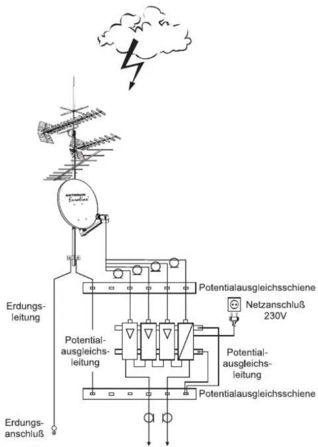
Fig. 12: Grounding of antenna
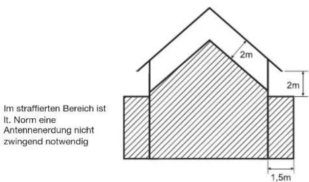
Fig. 13: Areas for antenna grounding
Technical Data
| Type KEA 650 KEA 750 KEA 850 KEA 1000 | |||||
| Order no. | white | 20010047 | 20010050 | 20010053 | 20010059 |
| graphite | 20010048 | 20010051 | 20010054 | 20010060 | |
| red-brown | 20010049 | 20010052 | 20010055 | 20010061 | |
| Reflector diameter mm 670 x 715 750 x 800 850 x 905 970 x 1040 | |||||
| Reception range GHz 10.70 - 12.75 10.70 - 12.75 10.70 - 12.75 | |||||
| Antenna gain at 11.70 GHz | dBi | 36 | 37.4 | 38.5 | 39.7 |
| Cross-polarisation decoupling1) | dB | 24 | 24 | 26 | 28 |
| Half-power beam width at 11.70 GHz | ° | 2.6 | 2.2 | 1.95 | 1.7 |
| Wind load2) | N | 451 | 569 | 736 | 962 |
| Max. permissible wind speed | km/h | 180 | 180 | 180 | 180 |
| Mast clamp range | mm | 30 - 90 | 30 - 90 | 30 - 90 | 30 - 90 |
| Adjustment range Elevation/Azimuth | ° | 0 - 80/360 | 0 - 80/360 | 0 - 80/360 | 0 - 80/360 |
| LNB support | mm | 40 | 40 | 40 | 40 |
| Packaging unit | pc. | 1 | 1 | 1 | 1 |
| Weight | kg | 4.5 | 4.9 | 6.2 | 7.4 |
^1) in the bore sight of the antenna at 10.95 GHz
2) At dynamic pressure of 800 N/m ^4 according to EN 60728-11
Tip
All data in this table are typical values!
Transport and Storage
▶ Transport and store the device in its original packaging.
Service Centre
If, contrary to expectation, you should have any problems with Kathrein Euroline quality products, please contact your specialist dealer or our service centre. The address of our service centre is:
Repair centre
autronic electronic-service GmbH
Hauptstraße 2a
Electronic equipment
Electronic equipment is not domestic waste – in accordance with directive 2012/19/EC OF THE EUROPEAN PARLIAMENT AND THE COUNCIL dated 04th July 2012 concerning used electrical and electronic appliances, it must be dis- posed of properly. At the end of its service life, take this unit for disposal at a designated public collection point.
Azimuth/Elevation Table
| TÜRKSAT ASTRA EUTELSAT EUTELSAT EUTELSAT | ||||||||||
| Geogr. coordinates 42.0° East 19.2° East 10.0° East 13.0° East 16.0° East | ||||||||||
| Latitude Longitude Azimuth Elevation Azimuth Elevation Azimuth Elevation Azimuth Elevation | ||||||||||
Germany
| Bad Reichenhall | 47.7 12.9 1 | 43.0 28.4 1 | 71.5 34.9 1 | 83.9 35.1 1 | 79.9 35.2 1 | 75.8 35.1 | ||||||
| Berlin | 52.5 13.4 1 | 45.5 24.4 1 | 72.7 29.7 1 | 84.3 29.9 1 | 80.5 30.0 1 | 76.7 29.9 | ||||||
| Bremen | 53.1 8.8 | 140.7 | 22.1 167.1 | 28.6 178.5 | 29.4 174.8 | 29.2 171.1 | 29.0 | |||||
| Cottbus | 51.8 14.3 1 | 46.3 25.4 1 | 73.8 30.6 1 | 85.5 30.7 1 | 81.7 30.8 1 | 77.9 30.8 | ||||||
| Dortmund | 51.5 7.5 | 138.7 | 22.9 165.1 | 30.0 176.8 | 31.0 172.9 | 30.8 169.1 | 30.5 | |||||
| Dresden | 51.1 13.7 1 | 45.3 25.7 1 | 73.0 31.3 1 | 84.8 31.5 1 | 80.9 31.6 1 | 77.1 31.5 | ||||||
| Emden | 53.4 7.2 | 139.1 | 21.2 165.2 | 28.1 176.5 | 29.0 172.8 | 28.8 169.1 | 28.5 | |||||
| Erfurt | 51.0 11.0 1 | 42.3 24.8 1 | 69.5 31.1 1 | 81.3 31.6 1 | 77.5 31.6 1 | 73.6 31.5 | ||||||
| Flensburg | 54.8 9.5 | 142.1 | 21.0 168.1 | 26.9 179.3 | 27.5 175.7 | 27.4 172.0 | 27.2 | |||||
| Frankfurt am Main | 50.1 8.7 | 139.4 | 24.5 166.4 | 31.7 178.3 | 32.6 174.4 | 32.4 170.5 | 32.1 | |||||
| Freiburg/BaWü | 48.0 7.8 | 137.6 | 25.8 164.9 | 33.8 177.1 | 34.8 173.1 | 34.7 169.1 | 34.3 | |||||
| Greifswald | 54.1 13.4 1 | 46.1 23.0 1 | 72.8 28.0 1 | 84.2 28.2 1 | 80.5 28.3 1 | 76.8 28.2 | ||||||
| Hamburg | 53.6 10.0 1 | 42.2 22.2 1 | 68.6 28.3 1 | 80.0 28.8 1 | 76.3 28.8 1 | 72.5 28.6 | ||||||
| Hannover | 52.4 9.8 | 141.5 | 23.1 168.2 | 29.5 179.7 | 30.1 175.9 | 30.1 172.1 | 29.8 | |||||
| Kassel | 51.3 9.4 | 140.7 | 23.8 167.6 | 30.6 179.3 | 31.3 175.4 | 31.2 171.6 | 31.0 | |||||
| Kiel | 54.3 10.1 1 | 42.5 21.6 1 | 68.9 27.5 1 | 80.2 28.0 1 | 76.5 28.0 1 | 72.8 27.8 | ||||||
| Koblenz | 50.3 7.5 | 138.2 | 23.8 164.9 | 31.3 176.8 | 32.3 172.9 | 32.1 169.0 | 31.8 | |||||
| Leipzig | 51.3 12.4 1 | 44.0 25.1 1 | 71.3 30.9 1 | 83.0 31.2 1 | 79.2 31.3 1 | 75.3 31.2 | ||||||
| Magdeburg | 52.1 11.6 1 | 43.4 24.1 1 | 70.4 30.0 1 | 82.1 30.4 1 | 78.3 30.4 1 | 74.5 30.3 | ||||||
| Mönchengladbach | 51.2 6.5 | 137.5 | 22.7 163.8 | 30.2 175.4 | 31.3 171.6 | 31.1 167.8 | 30.7 | |||||
| München | 48.1 11.6 1 | 41.8 27.5 1 | 69.8 34.2 1 | 82.1 34.7 1 | 78.1 34.7 1 | 74.1 34.6 | ||||||
| Neubrandenburg | 53.6 13.3 1 | 45.8 23.4 1 | 72.6 28.6 1 | 84.0 28.8 1 | 80.3 28.8 1 | 76.6 28.8 | ||||||
| Nürnberg | 49.5 11.1 1 | 41.8 26.1 1 | 69.3 32.8 1 | 81.4 33.3 1 | 77.4 33.3 1 | 73.5 33.1 | ||||||
| Osnabrück | 52.3 8.1 | 139.7 | 22.5 166.0 | 29.3 177.5 | 30.2 173.8 | 30.0 170.0 | 29.8 | |||||
| Passau | 48.6 13.5 1 | 44.1 27.9 1 | 72.4 34.0 1 | 84.6 34.2 1 | 80.6 34.3 1 | 76.6 34.2 | ||||||
| Pirmasens | 49.2 7.6 | 137.9 | 24.7 164.8 | 32.5 176.8 | 33.5 172.9 | 33.3 169.0 | 33.0 | |||||
| Plauen | 50.5 12.1 1 | 43.3 25.6 1 | 70.9 31.8 1 | 82.8 32.1 1 | 78.9 32.1 1 | 75.0 32.0 | ||||||
| Ravensburg | 47.8 9.6 | 139.4 | 26.8 167.1 | 34.3 179.5 | 35.1 175.4 | 35.0 171.4 | 34.8 | |||||
| Regensburg | 49.0 12.1 1 | 42.7 26.9 1 | 70.6 33.4 1 | 82.8 33.7 1 | 78.8 33.8 1 | 74.8 33.6 | ||||||
| Rostock | 54.1 12.1 1 | 44.6 22.5 1 | 71.3 27.9 1 | 82.6 28.2 1 | 78.9 28.3 1 | 75.2 28.2 | ||||||
| Stuttgart | 48.8 9.2 | 139.4 | 25.8 166.8 | 33.2 178.9 | 34.0 174.9 | 33.9 171.0 | 33.6 | |||||
| Trier | 49.8 6.6 | 137.1 | 23.8 163.7 | 31.7 175.6 | 32.9 171.7 | 32.6 167.8 | 32.3 | |||||
| Ulm | 48.4 10.0 1 | 40.1 26.5 1 | 67.7 33.7 1 | 80.0 34.5 1 | 75.9 34.4 1 | 72.0 34.2 |
Austria
| Bregenz | 47.5 9.8 | 139.5 | 27.1 167.3 | 34.7 179.7 | 35.4 175.6 | 35.3 171.6 | 35.1 | |||||
| Graz | 47.1 15.5 1 | 45.8 30.0 1 | 4.9 35.8 18 | 7.4 35.6 18 | 3.3 35.9 17 | 9.2 35.9 | ||||||
| Innsbruck | 47.3 11.4 1 | 41.2 28.1 16 | 9.4 35.2 18 | 1.9 35.7 17 | 7.8 35.7 17 | 3.7 35.5 | ||||||
| Klagenfurt | 46.6 14.3 1 | 44.2 30.0 17 | 3.3 36.2 18 | 6.0 36.2 18 | 1.8 36.4 17 | 7.7 36.4 | ||||||
| Lienz | 46.8 12.8 1 | 42.5 29.1 17 | 1.2 35.8 18 | 3.8 36.1 17 | 9.7 36.2 17 | 5.6 36.1 | ||||||
| Linz | 48.3 14.3 1 | 44.9 28.5 17 | 3.4 34.4 18 | 5.8 34.4 18 | 1.7 34.5 17 | 7.7 34.5 | ||||||
| Salzburg | 47.8 13.0 1 | 43.2 28.3 17 | 1.7 34.8 18 | 4.1 35.0 18 | 0.0 35.1 17 | 6.0 35.0 | ||||||
| Vienna | 48.2 16.4 1 | 47.3 29.4 17 | 6.2 34.6 18 | 8.5 34.3 18 | 4.5 34.6 18 | 0.5 34.7 |
Italy
| Bozen | 46.5 11.3 201.9 75.7 169.2 36.0 181.8 36.5 177.7 36.5 178.6 36.3 |
Switzerland
| Berne | 47.0 7.5 | 136.8 | 26.4 164.1 | 34.8 176.5 | 36.0 172.4 | 35.8 168.4 | 35.4 | |||||
| Zurich | 47.4 8.5 | 138.0 | 26.6 165.6 | 34.6 178.0 | 35.6 173.9 | 35.4 169.9 | 35.1 |


- Sicherheitshinweise
- Intended Use
- Scope of Delivery
- Accessories (Optional, Not Included)
- Safety Instructions
- DANGER
- WARNING
- Selecting the Installation Site
- Installing the Antenna
- Requirements for the Antenna Carrier
- Several antennas on a single antenna carrier:
- Installing the Reflector
- Installing the Mast Clamps
- Installing the Feed System Support
- Feed System (LNB)
- Aligning the Antenna
- Setting the Inclination (Elevation)
- Tip
- Setting the Direction (Azimuth)
- Fine Adjustment
- Finally Tightening of the Antenna
- Antenna earthing / lightning protection
- Notice
- Suitable as ground conductors is
- Unsuitable as ground conductors are
- Routing of ground conductors
- Transport and Storage
- Service Centre
- Electronic equipment
Brand : KATHREIN
Model : Euroline KEA 1000
Category : Receiver