
VOS 43/RA-1G2 - Receiver KATHREIN - Free user manual and instructions
Find the device manual for free VOS 43/RA-1G2 KATHREIN in PDF.


| Product Type | Satellite Receiver |
| Brand | Kathrein |
| Model | VOS 43/RA-1G2 |
| Dimensions (approx.) | 260 x 180 x 50 mm |
| Weight (approx.) | 1.2 kg |
| Power Supply | 12V DC, 1.5A |
| Power Consumption | Max. 18 W |
| Main Functions | Digital satellite TV reception, HD support, DiSEqC 1.2, USB playback, electronic program guide (EPG) |
| Input Connector | F-type, 75 ohms |
| Output Connectors | HDMI, SCART, RCA, optical audio |
| Supported Satellite Systems | DVB-S/S2 |
| Operating Temperature | 0°C to 40°C |
| Cleaning Instructions | Disconnect from power. Clean with a soft, dry cloth. Do not use liquids or abrasives. |
| Safety Precautions | Place on a stable, well-ventilated surface. Do not expose to rain or moisture. Unplug during thunderstorms. |
| Spare Parts and Repairability | Spare parts available through Kathrein service centers. Repairs should be done by qualified personnel. |
| General Information | Compliant with CE standards. Designed for indoor use only. |
Frequently Asked Questions - VOS 43/RA-1G2 KATHREIN
User questions about VOS 43/RA-1G2 KATHREIN
0 question about this device. Answer the ones you know or ask your own.
Ask a new question about this device
Download the instructions for your Receiver in PDF format for free! Find your manual VOS 43/RA-1G2 - KATHREIN and take your electronic device back in hand. On this page are published all the documents necessary for the use of your device. VOS 43/RA-1G2 by KATHREIN.
USER MANUAL VOS 43/RA-1G2 KATHREIN
House connection amplifi er
Merkmale
■ House connection amplifi er for modern HFC networks up to 1,2 GHz
■ Integrated high-efficiency switched-mode power supply unit
■ Power management: Unused amplifier stage switch-off for reduced power consumption
■ Die-cast housing with F-type connectors
■ Variable 6 dB interstage gain setting using on-board plug-in attenuators (delivery condition: higher gain)
■ The maximum operational levels also apply for operation with interstage attenuation
■ Interstage equaliser switchable with bridging plugs (6 dB pre-emphasis)
■ Integrated return path 5 – 204 MHz active/passive, off (switchable with bridging plugs)
■ Built-in variable attenuators (delivery condition return path: max. attenuation) and variable equaliser
■ LED to indicate operational mode
■ Test socket on output -20 dB (with directional coupler)
■ Test socket on input -20 dB (Return path 5 – 204 MHz)
■ Test sockets are terminated with the EMK 03 in the delivery status
■ For indoor installation
■ Conform to: EN 60728-11, EN 50083-2 und EN 32368-1
■ The amplifiers comply with the EMC directive 2014/30/EU and Low-Voltage Directive 2014/35/EU applicable at the time of shipping

Basic safety precautions

▶ Installation must be carried out by authorised specialist staff.
▶ Unplug from the mains before installation.
▶ Described amplifiers are exclusively for installation of HFC networks up to 1218 MHz.
▶ Any other use or failure to comply with these instructions will void the warranty or guarantee.
The amplifiers may only be installed in dry areas indoors. Do not install on or against highly combustible materials.
The amplifiers must be earthed when installed (Cu, minimally 4 mm 3 ).
The safety regulations set out in the current EN 60728-11 und EN 62368-1 standards must be complied with.

The supply voltage of the amplifiers is 230 VAC which can be fatal if touched directly!
The only reliable method of disconnecting the amplifiers from the mains is to unplug them.
▶ Do not touch live parts.
The power plug must be easy to operate as the means of cutting power to the amplifier, so the wall outlet must be close to the amplifier and easily accessible.
The amplifiers may only be installed and deinstalled in the voltage-free condition.
▶ Do not operate the amplifiers without the factory-fi tted protective cover over the power supply unit. The cover must be closed.
▶ No liquid-fi lled items may be placed on top of the amplifiers.
The amplifiers are not to be exposed to dripping or splashing water.
▶ Ambient temperature range -20 bis +55 °C.
Setting of the amplifier
To adjust the settings, a Phillips screwdriver is required to remove the housing cover. The settings options are also imprinted on the housing cover.
Forward path
① Pre-emphasis: 0 – 15 dB ⑤ Pre-emphasis: 0 – 20 dB
② Attenuation: 0 – 20 dB ⑥ Attenuation: 0 – 20 dB
③ Interstage → Attenuation: 6 dB ⑦ Attenuation: 0 dB | 10 dB
④ Interstage → Pre-emphasis: 6 dB

Optionally available accessories
■ De-emphasis equaliser: ERZ 120 (Order no. 272791)
■ Lightning arrester: KAZ 12 (Order no. 21810002)
Mounting

Return path
A | B | C: Operation mode return path: (see graphic and block diagram)


The following is required for installation:
■ Fixings: screws, max. ∅ 4.5 mm
■ F-type connector plug as per EN 61169-24

Risk of damage to property!
An inner cable conductor with a diameter greater than 1.2 mm, or the presence of burrs may damage the device inputs/outputs beyond repair.

Diameter
0.6 - 1.2 mm free of burrs

Block diagram
![graph TD A["Input 5–1218 MHz"] --> B["Preemphasis"] B --> C["Attenuation"] C --> D["Pre-emphasis"] D --> E["dB 0–20 dB"] D --> F["dB 0–15 dB"] E --> G["Antenna"] F --> H["Antenna"] G --> I["Antenna"] H --> J["Antenna"] I --> K["Antenna"] J --> L["Antenna"] K --> M["Antenna"] L --> N["Antenna"] M -->…](/content/2026/05/1010594/images/85cfec533cd483d18ff1e80321ec26aafa43f44371f7d0de910e3065c794e4ac.jpg)
Connection example

Technical data
| Type | Order no. VOS 43/RA-1G2 | 209500001 | ||
| Forward path | ||
| Frequency range MHz 258 – 1218 | ||
| Gain (variable through interstage gain) dB 34 | 40 | ||
| Amplitude deviation dB ± 1 | ± 1,5 | ||
| Setting range variable attenuator dB 0 – 20 | ||
| Setting range equaliser dB 0 – 15 | ||
| Setting range interstage attenuation (switchable with bridging plug) dB 0 | 6 | ||
| Setting range interstage equaliser (switchable with bridging plug) | dB | 0 | 6 |
| Max. operating level 9 (60-dB-CTB/CSO) flat with interstage pre-emphasis | dBμV | 108 | 114110 | 116 |
| Max. operating level 2) (BER <1E-9) flat with interstage pre-emphasis | dBμV 103 | 105 |
| Noise fi gure (interstage attenuation 0/6 dB) | dB | 5 | 6 |
| Number of outputs | 1 | |
| Return path | ||
| Frequency range MHz 5 – 204 | ||
| Gain (switchable passive/active) | dB | -1/28, can be disconnected |
| Setting range attenuation on amplifi er input (switchable with bridging plug) | dB | 0 | 10 |
| Setting range variable attenuator (amplifi er output) | dB | 0 – 20 |
| Setting range equaliser (amplifi er output) | dB | 0 – 20 |
| Noise fi gure | dB 5 | |
| Input level density (CINR: 50 dB) | dBμV/Hz | -11 |
| Dynamic range (input level density) | dB | 21 |
| Max. operating level (BER <1E-9) 24 channels QAM 256 | dBμV 106 | |
| General | ||
| Impedance input/output | Ω | 75 |
| Return loss input/output Forward path 3) Return path | dB | 1820 |
| RF connections | F-type connector | |
| Test socket output with directional coupler (5 – 1218 MHz) | dB | -20 |
| Test socket output return path (5 – 204 MHz) | dB | -20 |
| Nominal input voltage | VAC | 230 (50/60 Hz) |
| Power consumption (without/with return path) | W | 6/8 |
| Operational display | Green LED | |
| Protection class/protection category (to EN 60529) | II/IP 50 | |
| Temperature range | °C | -20 bis +55 |
| Dimensions | mm | 184 x 134 x 63 |
| Packing unit/weight | pc./kg | 1 (10)/1,7 |
1) To EN 60728-3; CENELEC channel plan 34 carriers; the level values also apply for interstage attenuation
2) To EN 60728-3 119 channels 256 QAM
3) To EN 60728-3 (category B); from 40 MHz ≥ 18 dB -1.5 dB/octave

Electronic equipment
Electronic equipment is not domestic waste – in accordance with directive 2012/19/EU OF THE EUROPEAN PARLIAMENT AND THE COUNCIL dated 4th July 2012 concerning used electrical and electronic appliances, it must be disposed of properly. At the end of its service life, take this unit for disposal at a designated public collection point.

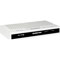
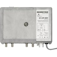


Brand : KATHREIN
Model : VOS 43/RA-1G2
Category : Receiver