
MSK 115/S2 - Receiver KATHREIN - Free user manual and instructions
Find the device manual for free MSK 115/S2 KATHREIN in PDF.


| Product Type | Satellite measuring receiver (MSK 115/S2) |
| Dimensions (W x H x D) | 207 x 67 x 137 mm |
| Weight | Approx. 1.5 kg |
| Power Supply | Internal rechargeable Li-ion battery (2.4 Ah, >3 h operation without LNB supply); external charger 100-240 V~, 0.7 A max, 50/60 Hz; 12 V DC car cable (1.7 A peak) |
| RF Input | F socket, 75 Ohm, short-circuit protected, loop-through output |
| Measurement Range | 950-2150 MHz |
| Input Level Range | 34-99 dBμV |
| Symbol Rate Range | 1-45 MSymbol/s |
| Modulation Support | DVB-S (QPSK), DVB-S2 (QPSK/8PSK), ASTRA DSL |
| Display | Signal strength, quality, MER/BER, constellation diagram, spectrum (60-1200 MHz span), histogram (SCR) |
| LNB Supply | 13/18 V, max 700 mA; DiSEqC™ 1.0, 22 kHz, SCR control |
| Memory | 1024 transponders / 512 satellites; user-defined transponder |
| Data Logging | Internal memory for measurement results; transfer via USB to PC (free software download) |
| Interfaces | USB (for software updates and data transfer), F jack-to-jack adaptors (replaceable) |
| Accessories Included | Carrying case, RF cable (2x F plugs), power supply with cables, USB cable, car charger, F adaptors |
| Safety & Maintenance | Replaceable F plugs (torque 1.0 Nm, spanner 11 mm); clean with lint-free cloth; dispose of electronics per WEEE |
| Spare Parts & Service | ESC Electronic Service Chiemgau GmbH (address in manual); original parts only |
| General Information | Language support: DE, EN, FR, ES, IT, NL, PL; compliance with EU directives |
Frequently Asked Questions - MSK 115/S2 KATHREIN
User questions about MSK 115/S2 KATHREIN
0 question about this device. Answer the ones you know or ask your own.
Ask a new question about this device
Download the instructions for your Receiver in PDF format for free! Find your manual MSK 115/S2 - KATHREIN and take your electronic device back in hand. On this page are published all the documents necessary for the use of your device. MSK 115/S2 by KATHREIN.
USER MANUAL MSK 115/S2 KATHREIN
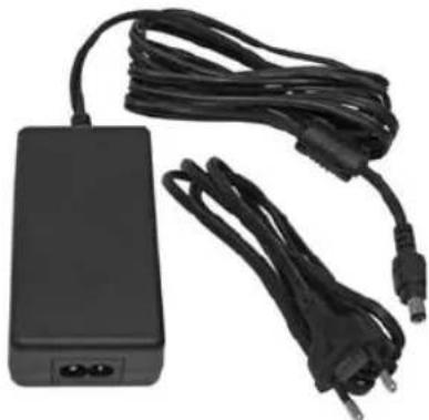
Netzgerät 1683208
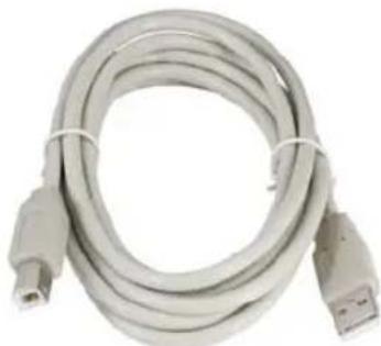
USB-Kabel
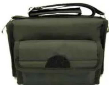
Textiltasche


Digital measuring instrument
MSK 115/S2

FOREWORD / IMPORTANT INSTRUCTIONS
Dear customer,
Thank you for choosing the Kathrein MSK 115/S2 measuring instrument. Please read the following instructions carefully so as to familiarise yourself with all the new functions before starting to use your instrument.
Please comply with all the instructions in this operating manual. KATHREIN-Werke KG has done all it can to ensure that the data and descriptions in this operating manual are correct and complete.
We reserve the right to make changes without notice. In particular, this applies to changes made due to technical advancements.
We would welcome any suggestions for improvements.
Publishing, copying, printing and distribution of this operating manual by electronic means, as a whole or in part, is only permissible with prior written agreement from KATHREIN-Werke KG.
All product names and brands used in this operating manual are the property of their respective owners.
VALIDITY OF THIS OPERATING MANUAL
This operating manual is applicable to the MSK 115/S2 measuring device, article no.: 21710036.
The following instructions are important for operating the measuring device and should be complied with in all circumstances.
GENERAL SAFETY INSTRUCTIONS
The MSK 115/S2 has been developed and manufactured in compliance with all relevant harmonised directives, standards and other technical specifications. The product is state-of-the-art and offers a high level of safety. However, this degree of safety can only be achieved during operation if the user complies with all necessary safety regulations.

Electronic equipment is not classed as household waste and must be disposed of properly in accordance with Directive 2002/96/EC OF THE EUROPEAN PARLIAMENT AND OF THE COUNCIL of 27 January 2003 on used electrical and electronic equipment.
At the end of its service life, take this device to a designated public collection point for disposal.

Spent batteries are classed as special waste!
Do not throw spent batteries into your domestic waste; take them to a collection point for used batteries!
CONTENTS
FOREWORD / IMPORTANT INSTRUCTIONS ...... 2
GENERAL SAFETY INSTRUCTIONS 2
CONTENTS.... 3
SAFETY INSTRUCTIONS...... 4
FUNCTIONS.... 5
ACCESSORIES 6
YOUR MEASURING INSTRUMENT 7
FRONT VIEW 7
REAR 7
SIDE VIEW 7
REGULAR MAINTENANCE OF REPLACEABLE F PLUGS 8
CHARGING THE BATTERY 9
SETUP MENU 10
OPERATING MENU 11
DISEQC™ COMMANDS 14
SCR CARRIER MODE.... 15
HISTOGRAM DISPLAY 15
SPECTRUM MODE.... 16
CONSTELLATION DIAGRAM.... 17
USING THE "CUSTOMIZE" FUNCTION 18
LOGGING MEASUREMENT RESULTS.... 20
LOG AS 000X 20
LOG ALL 20
LNB/CABLE TEST.... 20
LNB DRIFT 21
ORIENTATION 21
LOGGING MEASURED DATA 22
DATA TRANSFER.... 23
FAQ 24
SPECIFICATIONS.... 25
TECHNICAL APPENDIX.... 26
FEATURES 26
SERVICE 27
SERVICE CENTRE ADDRESS (REPAIRS, SPARE PARTS) 27
SAFETY INSTRUCTIONS

The safety instructions enclosed with the device must be followed at all times.
This sheet contains important information regarding the operation, installation location and connection of the device. Read these instructions carefully before setting up the device.
FUNCTIONS
Handy and compact measuring instrument for the optimal alignment of satellite reception systems. Display of signal strength and signal quality to enable optimal alignment of the antenna. 1024 transponders of max. 512 satellites can be saved. In addition, a transponder can be set by the user. Software updates enable the user to programme the measuring instrument for user-specific satellite transponders. The measuring instrument is very easy to operate, making it the ideal tool for antenna installers when setting up satellite systems.
ACCESSORIES
In addition to this operating manual, the following parts are included with the MSK 115/S2. Please check you have received them all. If any parts are missing, please contact your dealer.

Use only original spare parts, otherwise the safety of the measuring instrument may be compromised!
DC in-car charging cable with 2 Amp fuse

Measuring cable 2 x F plugs

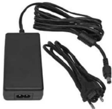
Power supply unit 1683208
USB cable

Fabric carrying case
F jack-to-jack adaptors (fi tted)

The power supply unit must satisfy the regulations applicable in your locality. If you do not receive the correct plug-in power supply unit for your locality, you can order a suitable one from Kathrein or from a local dealer/importer.
Note: We reserve the right to make changes to the parts listed above.
Please dispose of the packaging material in an environmentally responsible way.
YOUR MEASURING INSTRUMENT
FRONT VIEW

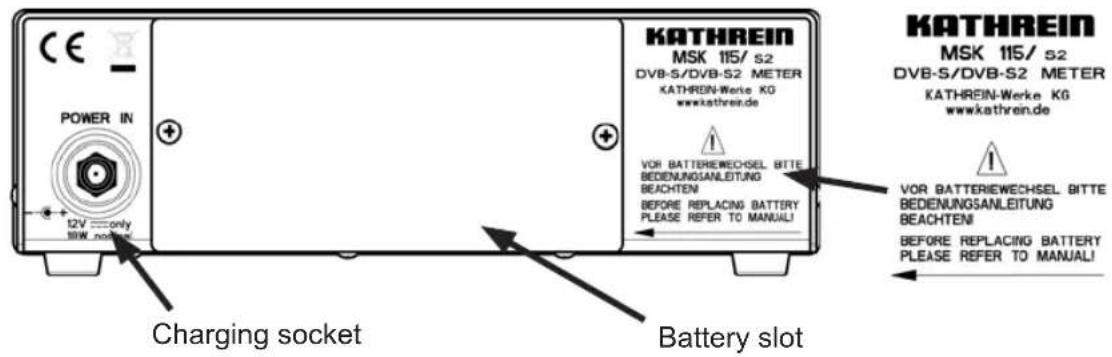
REAR
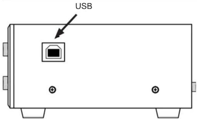
SIDE VIEW
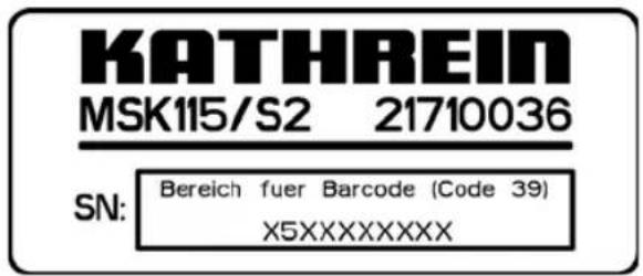
Serial number sticker (on the underside)
*) The input and output sockets on the MSK 115/S2 are fitted with a replaceable F jack-to-jack adaptor (F roll). If the sockets are damaged, they can be removed individually using the hexagonal lug and replaced without having to open the measuring instrument. Tightening torque for replacement 1.0 ± 0.2 Nm, spanner size 11 mm (7/16").
REGULAR MAINTENANCE OF REPLACEABLE F PLUGS
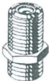
Note: Your new measuring instrument is equipped with replaceable F plugs that must be checked and replaced at regular intervals to ensure continued reliable performance.
To remove the plugs, use a 7/16 inch/11 mm spanner with torque setting 1 Nm.

Clean the surrounding area carefully with a lint-free cloth to prevent deposits from falling into the F plug hole.

Tip: Check whether any copper fragments have collected in the F plug on the measuring device. If necessary, these can be removed using a dry cotton bud.
CHARGING THE BATTERY
The measuring instrument is NOT fully charged when delivered. Before first use, the battery should be charged once for 24 hours.
The battery pack can easily be changed. The power supply must be unplugged before the unit can be opened. To replace the battery, remove the measuring instrument from its protective case, open the cover on the underside of the instrument and undo the battery connections.
Insert and connect up the new battery. Refit the cover and fully charge the instrument to ensure safe battery operation.
The DC adapter supplied also allows the battery to be charged from a car battery.
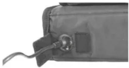
Charging using the power supply unit and in-car charging cable
The bottom side of the bag features a small flap with hook-and-loop fastener which protects the power supply and charging cable. Plug the power supply unit or in-car charging cable into the socket, and if using the in-car charging cable, plug the other end into the car socket (cigarette lighter and standard 12-Volt outlet).
If charging in the vehicle, only use the cable supplied. Other cables may damage the instrument and lead to invalidation of the guarantee/warranty. The MSK 115/S2 can be left connected to the charging source for an extended period in the “quick charging” state of charge. If the unit is to be charged for a long period of time, it will switch to trickle charging; in this mode it is only charged very little so that the unit’s inner components do not suffer damage and so that the unit can remain plugged to the power source with its accu pack for a prolonged period of time. Very little charge is delivered in this state, meaning that the instrument can remain on charge for extended periods without damage to its internal components or to the battery pack. When the battery is fully charged, the instrument will display “Fully charged”.
Note: Whilst it is being charged, the measuring instrument cannot be switched on.

The ambient temperature when the power supply is in use must be less than 40°C !
The mains cord must not be replaced with an inadequately rated one!
SETUP MENU
To display the "Setup" menu, switch the MSK 115 off and then press the DOWN key once. The following menu items can be accessed from this menu.
| Exit |
| Backlight onClicking offBrightness 15Contrast 15Sleep 15MEnglishRF dBuVLNB 13V/18VDefaultsAzimuth true1.0Ka-0021Cities^For more |
Use the cursor keys to navigate through the set-up menu (▲▼) and modify values (◀) After you have made all the settings, return to the first menu item (Exit). Press the◀or▶button to load your changes. The measuring instrument now switches itself off.
Note: The entire menu is shown here, however, on the LCD display only four options are shown at a time.
- The following languages are available for menu items and display information: German, English, French, Spanish, Italian, Dutch and Polish.
- The RF can be displayed in dBμV, dBm or dBmV mode
- The LNB voltage 13/18 Volt can be switched off completely. If the LNB voltage is switched to 0 Volt, the satellite display alternates between the selected satellite setting and “LNB 0V”.

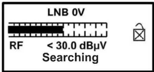
- To revert to the original setup settings, select "Defaults" and press the ▶ button. This procedure will not affect the satellite settings stored in the memory
- The "V1.0Ka-21" display is only intended as a Kathrein reference number and may vary.
OPERATING MENU

MSK 115/S2 keypad. All functions of the measuring instrument can be controlled using these buttons.
When you have securely installed your satellite dish in the correct direction, connect the LNB to the measuring instrument using a short cable (if possible only 1.5 m long). Tip: Do not fully tighten the satellite dish mounting clip. This will enable you to still make fine adjustments to the position of the dish.
To switch on the measuring instrument, press the ▲button once. The animated Kathrein logo will appear.

The next screen shows the measuring instrument data, including the model, version, satellite list loaded and the battery charge level in percent.
Use the band buttons to scroll through the available satellites until the required satellite is displayed.
Rotate the satellite dish in the general direction of the satellite you are looking for and slowly search the sky. After each scan, change the height. As you search the sky and pass each satellite, the scale value on the measuring instrument and the beep frequency change.
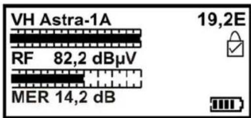
As soon as you have located your satellite, the measuring instrument tone changes and it shows "Found" on the display. A locked carrier is indicated by a closed padlock.
To obtain the highest possible RF and MER values, you must set the optimum values for your chosen satellite by fine tuning the azimuth, elevation and polarisation. Carefully tighten the securing screws (please observe the technical documentation enclosed with the satellite reflector) whilst monitoring the display to achieve the best reception quality.
Use the ▼ button to switch the display from MER to MER (linear) and to BER.
OPERATING MENU
| Exit |
| DiSEqC |
| Spectrum |
| Spectrum ρ |
| For more |
| DiSEqC |
| Spectrum |
| Spectrum ρ |
| Constellation |
| For more |
| DVB-S2 |
| DSL |
| Custom |
| ▶ Customize |
| For more |
| Spectrum ρConstellationDVB-S2 |
| DSLFor more |
| DSL |
| Custom |
| Customize |
| ▶ LNB 21V |
| For more |
| LNB 21V |
| ►Orientation |
| Log as 00000 |
| Log All |
| For more |
To call up the sub-menu on the display, press the ▲button. Use the cursor buttons to select from the various options. The measuring instrument can be switched off at any time. To do so, press and hold down the ▲button. If "Exit" is highlighted, you can also use the ▶button to switch off the measuring instrument.
The DiSEqC™ LNB function allows you to issue a DiSEqC™ switching command. There are 16 SAT levels selectable for this. As soon as a command has been selected, the instrument automatically reverts to the search screen. To exit this screen without triggering the command, you can scroll back and highlight "Exit". A comprehensive explanation of the spectrum and constellation menu can be found on pages 16 and 17 in this operating manual.
The “Customize” mode is a function that allows you to define your own carrier on to which you wish to lock. This can be very useful if you wish to optimise a specific service after the satellite has been located. This function can also be used for a “single cable system”. This selection can also be saved separately from your pre-defined selection. A comprehensive explanation of the “Enter carrier” mode can be found on page 18 onwards.
DVB-S2: Here you can switch between DVB-S2 and DVB-S1 operation modes
DSL: Here you you can select the operation mode for measurement of data transponders
The "LNB 21V" function is intended for future extended functions in a single cable system.
This setting only works in the "Custom" - "Carrier" menu.
For the satellites you have set up, you can query the correct position in your location for exact alignment. To do so, follow the logical menu navigation to set your location. The instrument will then display the data for the precise alignment of the antenna.
OPERATING MENU
| DVB-S2DSL |
| Custom |
| CustomizeFor more |
| Orientation |
| Log as 00000 |
| Log All |
| LNB Drift |
| For more |
| Log as 00000 |
| ▶ Log All |
| LNB Drift |
| LNB/Cable Test |
| For more |
| Log as 00000 |
| Log All |
| LNB Drift |
| ▶ LNB/Cable Test |
| For more |
| Log as 00000 |
| Log All |
| ▶ LNB Drift |
| LNB/Cable Test |
| For more |
Pressing „Custom“ calls up the list of custom carriers. After selecting this list, you can select a previously saved carrier.
The "Log as 000xx function allows the most recent measurement result to be saved under a sequential number. The additional "Kathrein LOG reader" software allows these results to be displayed in a table on the PC.
In "Log All", all transponders for the configured satellite are measured and saved.
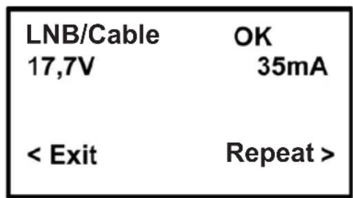
The "LNB/Cable Test" function provides a test current to check the cable resistance to the LNB. If this is too low or the cable is open circuit, the message: "LNB/Cable fault" appears.
A frequency deviation in the implementation of an LNB is displayed here. If the deviation is more than 3 MHz, the display will read: "LNB Problem"
OPERATING MENU
DISEQC™ COMMANDS
Requested satellite level: DiSEqC
TM commands transmitted:
| Exit | |||
| SAT A_Ver_Low | |||
| SAT A_Ver_High | |||
| SAT A_Hor_Low | |||
| SAT A_Hor_High | |||
| SAT B_Ver_Low | |||
| SAT B_Ver_High | |||
| SAT B_Hor_Low | |||
| SAT B_Hor_High | |||
| SAT C_Ver_Low | |||
| SAT C_Ver_High | |||
| SAT C_Hor_Low | |||
| SAT C_Hor_High | |||
| SAT D_Ver_Low | |||
| SAT D_Ver_High | |||
| SAT D_Hor_Low | |||
| SAT D_Hor_High | |||
| frequency | |||
| ASTRA | SCR | 1) LNB | 11836 |
| ASTRA | SCR | 1) 4SU 2) | 11836 HH |
| ASTRA | SCR | 1) 8SU 2) | 11954 HH |
| HOTBIRD | SCR 1) LNB | 11604 | |
| HOTBIRD | SCR 1) 4SU 2) | 11054 HL | |
| HOTBIRD | SCR 1) 8SU 2) | 11604 HL | |
HH HL
| E0 10 38 F0 |
| E0 10 38 F1 |
| E0 10 38 F2 |
| E0 10 38 F3 |
| E0 10 38 F4 |
| E0 10 38 F5 |
| E0 10 38 F6 |
| E0 10 38 F7 |
| E0 10 38 F8 |
| E0 10 38 F9 |
| E0 10 38 FA |
| E0 10 38 FB |
| E0 10 38 FC |
| E0 10 38 FD |
| E0 10 38 FE |
| E0 10 38 FF |
| E0 10 5A 0D 99 |
| E0 10 5A 0D 35 |
| E0 10 5A 2D 52 |
| E0 10 5A 09 5F |
| E0 10 5A 09 46 |
| E0 10 5A 39 D0 |
The hexadecimal DiSEqC TM commands sent are standardised commands based on a 22 kHz grid. They allow DiSEqC TM switches, DiSEqC TM matrices and respective single cable systems to be controlled.
1) "SCR" stands for Single Cable Router
2) "SU" stands for SubScriber
OPERATING MENU
SCR CARRIER MODE
In order to use the MSK 115/S2 SCR carrier functions, the device must be set to DVB-S1 mode.
For measuring on SCR systems, the carriers can be switched to 1400 MHz.
To switch on the SCR system carrier, fi rst call up the DiSEqC™ menu and press the downward arrow key until the single-cable system can be selected (e.g. ASTRA SCR 4SU, i.e. ASTRA single-cable matrix system for 4 subscribers). Afterwards, press the > button to send the DiSEqC™ command which activates the SCR carrier on 1400 MHz.
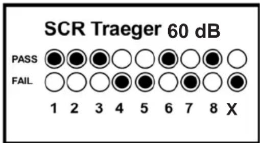
A transponder list will then appear, Press the < or > button until the item „SCR 60 dB“ appears. A histogram diagram will be displayed.
HISTOGRAM DISPLAY

The MSK 115/S2 has a histogram display. This can be used in SCR single cable systems to measure up to 8 different frequencies at the same time.
These frequencies are typically:
SCR1 = 1,284 MHz
SCR2 = 1,400 MHz
SCR3 = 1,516 MHz
SCR4 = 1,632 MHz
SCR5 = 1,748 MHz
SCR6 = 1,864 MHz
SCR7 = 1,980 MHz
SCR8 = 2,096 MHz
The MSK 115/S2 only activates the carrier at 1400 MHz; if other SCR carriers are switched on through other devices, the MSK 115/S2 will display these, as seen in the example above.
The plotted line corresponds to a level of 60 dB µ V.

Press ▼o display the SCR channels in a simple logic diagram. If the level of some SCR channels is too low to guarantee safe operation of the system, this logical display will simply show a "PASS" or "FAIL" for each channel, as in the examples shown here.
OPERATING MENU
SPECTRUM MODE
You can enter spectrum mode via the sub-menu (should be press the ▲button whilst the signal level or the Carrier-to-noise ratio is shown on the display). Switch to the “Spectrum” line and press the ▶button. The screen displays the spectrum.

If you select the menu item „Spectrum“, the reference level at the upper end of the scale is 99 dBμV
If you select the menu item „Spectrum O“, the reference level at the upper end of the scale is 79 dBμV
The display is centred on the frequency of the selected transponder (on 10728 MHz in the example of the low band setting shown). The “Span” frequency display range (the frequency range displayed on the screen) is set to 240 MHz as standard, allowing 8 adjoining carriers with 30 MHz spacing to be shown. Pressing the ▼ button allows the “Span” to be selected as a value between 60 MHz (especially for zooming in on a carrier) to 1200 MHz.
Use the ◀ and ▶ buttons to centre the selected frequency on the display. When so doing, take care not to exceed the limit of each band. These limits are marked with an arrow to the right (lower limit) and to the left (upper limit). The low band covers the range from 10700 MHz to 11900 MHz and the high band the range from 11550 MHz to 12750 MHz, meaning that the low band and the high band for universal LNBs overlap somewhat.
The RF level is shown by a bar at each frequency that is sampled (see diagram). There are areas between the carriers in which there are low-level signals, and the larger the distance between peaks and troughs the better the carrier-to-noise ratio. A good carrier-to-noise ratio is important for fault-free reception!
The top line of the display can be toggled between “Centre” with the selected frequency (displayed on the dotted vertical line in the middle of the display) and “Span” in MHz In the “Span” view, the polarisation of the carrier is shown as (H)orizontal or (V)ertical. If the high band is selected, the 22 KHz tone symbol Appears alongside the polarity.

The spectrum information bar at the top edge of this screen toggles between the current frequency and the span that is being used.

Note: You can exit spectrum mode at any time by pressing the ▲ button once. The instrument then reverts to the search display for the previous selection.
Tip: If you have defined your own carrier, it too can be viewed in spectrum mode.
OPERATING MENU
CONSTELLATION DIAGRAM
When the measuring instrument has locked on to a DVB-modulated carrier, "Constellation" mode is available via the sub-menu (press the ▲ button whilst the signal level or carrier-to-noise ratio is displayed). If no lock-on has been achieved, this option remains greyed out.
Scroll down the sub-menu until “Constellation” is highlighted, then press the ▶ button. The display will show the constellation and a list of the current transponder settings.
The graphical display shows the quadrants of the signal. A “good” display shows an agglomeration of dots near the outer corner of each quadrant. The more concentrated the agglomeration, the better the quality of the signal being received; if dots are scattered outside the agglomeration, these indicate interference on the signal, phase errors or other undesirable artefacts.
The objective is to achieve the best possible result; this can be achieved by careful alignment of the LNB. The constellation diagram gives confirmation that the signal setting is good.
On the right side of the display, a list of the parameters of the currently selected transponder is displayed:
Frequency in MHz: This is the measured frequency after “Synchronisation” by the automatic frequency regulation of the measuring instrument. This means that the displayed value can easily vary from the value set in the configuration file;
Symbol rate in kBaud (kSamples/second): The data rate is critical for identification and locking on to the selected carrier;
FEC (Forward Error Correction) value: Data for the selected carrier matches a value from the short list of standard FEC values;
IQ Standard shows that the IQ conforms to this and has not been swapped.
The state of charge of the battery pack is shown at the bottom right.
Tip: The constellation diagram can be used to trace defective components that underlie LNB problems, cause malfunctions and compromise the quality of the digital signal.

This image shows a typical QPSK constellation diagram.
This image shows a typical 8PSK constellation diagram.
OPERATING MENU
USING THE "CUSTOMIZE" FUNCTION
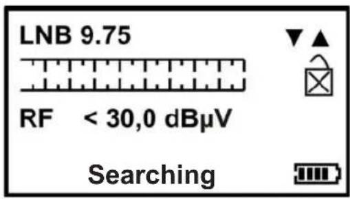
Navigate to the "Custom" menu and select the custom transponder to be changed.
You can then open the "Customize" menu and modify this transponder as required.
First use the ▲ and ▼ buttons to select your local oscillator. There are various local oscillators available, some of which also have a 22 kHz tone available. The local oscillators are listed in the table below.
| 9.75 | 18.25 | Ka-Band | |
| 10.6 | 22KHz tone on | 18.75 | Ka-Band |
| 10.0 | 19.25 | Ka-Band | |
| 10.25 | 19.75 | Ka-Band | |
| 10.5 | 5.15 | C-Band | |
| 10.7 | 5.76 | C-Band | |
| 10.7 | 22KHz tone on | 5.95 | C-Band |
| 10.75 | |||
| 10.75 | 22KHz tone on | ||
| 11.25 | |||
| 11.25 | 22KHz tone on | ||
| 11.3 | |||
| 11.3 | 22KHz tone on |
When you have made your selection, press the ▶ button to set the oscillator frequency.
(The menu shown here is just for explanation; it is not visible in this form).
After the local oscillator has been set, the desired carrier frequency can be selected.
Note: The selected local oscillator determines the available frequency range.

To set the desired frequency, use the ▲ and ▼ buttons to change the highlighted number. Pressing the ◀ or ▶ button switches to the next number. When the required frequency has been reached, press the ▶ button to switch to the "Symbol rate" screen. Take care not to select values outside the valid range (e.g. 20700 MHz in Ku band mode).

The symbol rate is set in the same way as setting the frequency for the desired signal. Use the ◀ and ▶ buttons to highlight the desired number and use the ▲ and ▼ buttons to change the value. Symbol rates can be set to values between "01000" and "45000". When the desired symbol rate has been reached, press the ▶ button to switch to the "FEC" screen.
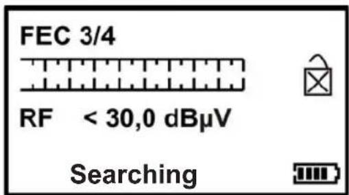
This screen allows you to select the desired FEC. If you do not know the FEC, select "Unknown". The MSK 115/S2 will test all FEC settings during the search after "Enter carrier". The available FECs are listed in the table on the right. Press the ▶ button to switch to the "LNB Voltage" screen.

OPERATING MENU

The desired LNB voltage can be selected in this menu (18 Volt for horizontal or 13 Volt for vertical). Press the ▶ button to switch to the "IQ" screen.
Note: If you use a block LNB for a single cable installation, 13 Volt is typically chosen as the supply for this type of LNB, since the polarisation is set manually. Look up the precise requirements in the documentation for your LNB.

Here the IQ can be switched between Standard (not swapped) and Swapped. Sometimes the Swapped setting is necessary for the IQ in order to achieve locking on. Mostly however it should be set to Standard (not swapped). If you have been unable to achieve locking on, use the Swapped setting.
When you have made the setting, use the ▶ button to open the "Save and Exit" or "Discard" screens.

This function is only available in DVB-S2 mode. You can set this function here depending on whether the satellite operator transmits pilots or not. In the „Auto“ setting, the MSK 115/S2 automatically identifies the configuration.
Once all parameters have been set, it is possible to save a carrier separately from the pre-defined selection.
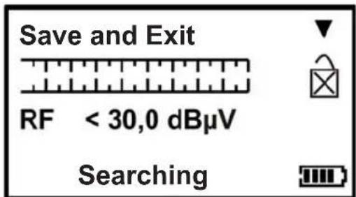
Pressing the ▼ button on this screen saves your own "Custom" carrier. The screen now switches into search mode, in which you can use your carrier settings to find the desired service.
If you do not wish to save your settings, press the ▶ button to bring up the "Discard" screen. If you wish to use your carrier during a later installation, you can call it up again from the sub-menu via the "Custom" option.
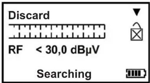
On this screen, press the ▼ button to discard all the values you have set. The measuring instrument returns to search mode for the satellite last selected before calling up "Custom" mode. Alternatively, press the ▶ button to scroll through the carrier options to select another carrier of your choice.
Note: The MSK 115/S2 is only compatible with DVB-QPSK-modulated carriers, as well as DVB-S2, 8PSK and ASTRA-DSL (ASTRA-2-Connect), and will not achieve locking on with other modulation types. When using lower symbol rates (less than "04000"), the locking on process may take several seconds. The alignment speed of your antenna must be significantly slower.
Tip: Various frequently occurring carrier constellations can lead to a multiple lock-on. Carriers with an FEC of 3/4 and a symbol rate of 27500 are likely to lock on to different satellites.
OPERATING MENU
LOGGING MEASUREMENT RESULTS
Before you use the Log function, you must first register the selected satellite. Make sure that the reception levels are as good as possible. You can download the logging software required to read out the measuring instrument's saved data entries from Kathrein's download page on the Web. The software also allows you to export the data as a CSV file.
LOG AS 000X
Press the ▶ button to select the function „Log as 000x“. The measured value of the latest measurement (level and configuration of the selected transponder) will be saved and numbered under this item; the storage number will increase by one every time you save. Make a note of the storage number on a slip of paper prior to saving; you will need it later on when the measuring instrument log data is evaluated.
LOG ALL
Press the ▶ button to select the function „Log all“. The level and settings of the selected satellite (e.g. all levels) will be saved and numbered under this item; the storage number will increase by one every time you save. Make a note of the the storage number on a slip of paper prior to saving; you will need it later on when the measuring instrument log data is evaluated.
LNB/CABLE TEST
The “LNB/Cable Test” is a quick function for searching for possible faults; it can be used to indicate whether any problems are present.

The test results appear after a few seconds as shown below.
Note: The functions listed above are intended only for display purposes.

OPERATING MENU
LNB DRIFT
HH Astra 1A 19.2 E
Min - 0.241
Drift - 0.241 MHz
Max - 0.240

The “LNB drift” function can be used to determine a frequency deviation of a LNB or conversion oscillator in the satellite system.
If this deviation ("Drift") is more than 3 MHz, a "LNB problem" is displayed.
ORIENTATION
To simplify alignment of the antenna, you can calculate the alignment position for the use of a compass for your location and the satellite previously set up in the measuring device.
To do so, navigate to the "Orientation" operating menu. Select "Change country". Press the and buttons to scroll alphabetically through the saved countries. Example for Deutschland (Germany):
under D (now press ▶) you get to DE (now press ▶), then to Deutschland (now press ▶), now Deutschland is selected.
If you now press ▶you are automatically taken to the major cities saved under Deutschland. Choose the nearest saved city to your location. These names are again stored alphabetically. Use the ▲/▼ buttons to scroll to your city and select it in the menu order using the right-hand button.
Finally, the theoretical default values of the satellite antenna are displayed.
You can navigate one step back in the menu selection at any time using the button.
If you want to call up the last value displayed again without changing the city selection, select the “Orientation” menu item and then “Continue” to return to the display of the last calculation.
Here are some examples:
![graph LR A["Back Select KMP Select City"] --> B["Back Select MaMu Select City"] B --> C["Back Select MudMun Select City"] D["Back Select Munchen Select City"] --> E["Munchen Azimuth Mag 167.7Elevation + 34.2Skew + 0.3"]](/content/2026/05/859355/images/dbb205eca569271aca80935b2af0fb8c985a57ec6e0b21f280b9d3b759c4452a.jpg)
LOGGING MEASURED DATA
The software referred to here for reading previously saved values is not supplied as standard! It is available for download from ESC-Kathrein under "MSK115-S2 Meter Log".
Before starting this program, make sure that the USB driver has already been downloaded and installed.

Start the "MSK115-S2 Meter Log" by double clicking on the "MSK115-S2 Meter Log" symbol. A small program window appears.
Connect your MSK 115/S2 to your PC using the USB cable supplied. Wait until the measuring instrument automatically switches into "Programming" mode, then click on the "Read" menu item.

As soon as the fi le has been read, you will see the "Transfer complete" message displayed.

Click on "OK" to obtain a table with your logged measurements. You can now export this data in CSV format for use with other Office programs. If the table has already been closed you can call it up again under "View".
| ID | Name | Longitude | dBm | dBuV | dBmV | Locked Pilots | IQ Swap | MER | QBER | Nominal Freq kHz | Measured Freq kHz | Nominal Sym. Rate | Measured Sym. Rate | Standard | Code Rate |
| 00000-000 | VL Astra1A 19.2E | 19.20E | -29.15 | 76.6 | 19.60 | Y | 14.1 | 2.931410E-003 | 11597000 | 11596887 | 22000 | 22000 | DVB-S1 | QPSK 5/5 | |
| 00001-000 | HL Astra1A 19.2E | 19.20E | -29.55 | 75.2 | 19.20 | Y | 15.0 | 5.071000E-005 | 11671000 | 11670626 | 22000 | 22000 | DVB-S1 | QPSK 5/5 | |
| 00002-000 | VH Astra1A 19.2E | 19.20E | -31.25 | 77.5 | 17.50 | Y | 13.9 | 1.195827E-002 | 12480000 | 12479583 | 27500 | 27500 | DVB-S1 | QPSK 3/4 | |
| 00003-001 | HH Astra1A 19.2E | 19.20E | -30.95 | 77.8 | 17.80 | Y | 14.5 | 1.800000E-007 | 11836000 | 11836063 | 27500 | 27500 | DVB-S1 | QPSK 3/4 | |
| 00003-002 | VL Astra1A 19.2E | 19.20E | -28.95 | 79.8 | 19.80 | Y | 13.9 | 7.802970E-003 | 11597000 | 11596887 | 22000 | 22000 | DVB-S1 | QPSK 5/5 | |
| 00003-003 | HL Astra1A 19.2E | 19.20E | -29.35 | 75.4 | 19.40 | Y | 15.9 | 2.417960E-003 | 11671000 | 11670627 | 22000 | 22000 | DVB-S1 | QPSK 5/5 | |
| 00003-004 | Astra SCR | 19.20E | -29.5 | 75.7 | 19.70 | 11400000 | 11405895 | 27500 | 27506 | DVB-S1 | QPSK 3/4 | ||||
| 00003-005 | VH Astra1A 19.2E | 19.20E | -31.15 | 77.6 | 17.60 | Y | 13.9 | 2.344468E-001 | 12480000 | 12479583 | 27500 | 27501 | DVB-S1 | QPSK 3/4 |
If you wish to delete the log data currently held in the MSK 115/S2, select the "File" menu item and click on "Delete".
Remember: If you delete the log data held in the measuring instrument, the saved entries will be deleted but the counter will not be reset. Each new item of measured data that is added will be given a sequential number.
DATA TRANSFER
The data transfer software referred to here is not supplied as standard with the measuring instrument! It is available for download from ESC-Kathrein under “MSK115-S2 Firmware Load”. After the USB drivers have been installed, you can download the updated transponder list from the ESC Kathrein Download website as an update for the MSK 115/S2. Go to www.esc-kathrein.de and follow the instructions listed below to download new software onto your measuring instrument.
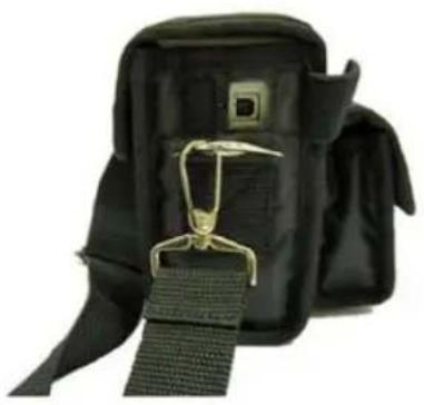
1) Wait until the MSK 115/S2 displays "Program mode" (the display may fl ash and the buzzer sound while communication is being established; this does not indicate a fault).
Programmierung
Important: The software must be installed, without the use of german Umlauts (ä=ae), in a common directory.

2) Make sure that the USB port has been activated.
Click on "Upgrade".
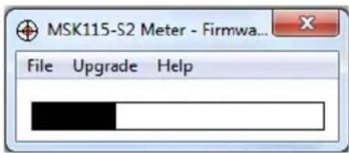
The upgrade menu will appear after a few seconds. Click the "Upgrade" button to begin transmission.
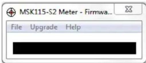
3) When it is completed, a window with the message "Upgrade Complete!" will appear. Click on "OK" and close the program.
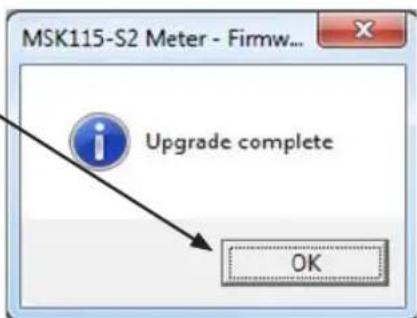
Disconnect the measuring instrument from the computer → Switch on → Ready for use.
Trouble-shooting to overcome fi le transfer problems.

If the error message "Error - Ack not received" is displayed, check that the USB connection has been established correctly and that the USB cable is not damaged.
FAQ
Fault "Ack Not Received"
1) Make sure that the USB cable has been connected correctly
2) Battery is too low.
Fault at the USB connection
1) Driver not found (the driver can be downloaded from the Kathrein website)
2) Check that the USB cable is correctly connected
3) The USB cable may be damaged or a bad connection may be affecting communications
4) The USB connection is damaged.
Display "I2C Error"
A 12 C error means that the built-in electronic components cannot establish a correct connection with the built-in receiver component. As a rule, this can be traced to the following causes:
1) The battery voltage is too low (when the measuring instrument is in a cold environment, the battery operating time is reduced)
2) Connecting the LNB whilst the measuring instrument is switched on can lead to a voltage spike, which can generate an I2C error. Do not connect the LNB unless the measuring instrument is switched off.
The measuring instrument shuts down
1) The battery voltage is too low
2) The timer is activated - check the timer setting in the "Setup" menu
3) The LNB has a short circuit or is drawing excessive current.
The measuring instrument has not found any lock-on
Make sure that you have downloaded a current transponder list for your measuring instrument; check if there is another, more current list available and update if necessary.
Apple MAC
The software is not MAC-compatible.
Storage
Tip: To keep the battery in good condition, if the instrument is being used only infrequently, charge it overnight at least once every two weeks. If the instrument is being used every day, we recommend that it is charged overnight before the next working day, so as to have the maximum battery capacity available.
SPECIFICATIONS
Charging
- Universal external charger 100 V\~ ... 240 V\~ 0.70 A max. 50/60 Hz. Intelligent battery charger (with CE mark) with Delta V/Delta T detection, quick charge and also trickle charge.
• DC 12-V in-car charging cable (1.7 A peak). - 5.5/2.1 mm socket for external charging using a 12-V DC in-car charging cable with 2 A fuse.
- Operating time with a fully charged 2.4 Ah Lithium battery is more than 3 hours (without LNB supply)
Connections
- LNB input via F socket. Impedance 75 Ohm with short circuit protection - 0.9 A automatic current limitation
- Loop-through output for further external signal processing
- Computer interface: USB port for updating the satellite settings
Spare parts for the measuring instrument are obtainable from ESC (see “Service” in the Appendix for the address).
TECHNICAL APPENDIX
FEATURES
● Measurement range: 950-2150 MHz
● Input level range: 34-99 dBμV
● Input data rate: 1-45 MSymbol/s
● Level and BER measurement (MER, with DVB-S2 also DER measurement)
● BER bar graph display in linear or logarithmic format
● QPSK/8PSK constellation diagram
● Display of the frequency spectrum with selectable span (60, 120, 240, 480, 960 and 1200 MHz)
● Acoustic and optical signal quality and signal strength display
● Quick test for LNB current
● Level indication either in dBμV, dBmV, dBm or linear in 256 increments
● 1024 transponders or 512 satellites can be set
- User-defined transponder setting
● Easy adjustment and change of satellite parameters through software updates
● Facility to save measurement results in the instrument
● Facility for transferring measurement results to a PC by USB cable
● Power supply via built-in rechargeable battery
● Battery capacity for more than three hours continuous duty
● Battery charging with external 240 V charger or external 12 V DC supply
● LNB supply voltage: 13/18 V, max. 700 mA
- Control signal: DiSEqC™1.0, 22 kHz, SCR single cable system control signals for ASTRA 19.2° and Hotbird 13.0°
● RF input: 75 Ohm, F plug, with loop-through output
- USB interface for software updates
- Includes case, RF cable with F plug, power supply unit with cable, 12-V connection cable, USB computer connection cable, two ready assembled F jack-to-jack adaptors
● Dimensions W x H x D (mm): 207 x 67 x 137
● Weight (kg): approx. 1.5
SERVICE
If after reading this operating manual you have further questions on the correct start-up or use of the instrument, or if you encounter unexpected difficulties, please contact KATHREIN-Werke KG Technical Customer Support:
Tel: +49 8031 184-700
Fax: +49 8031 184-676
SERVICE CENTRE ADDRESS (REPAIRS, SPARE PARTS)
ESC
Electronic Service Chiemgau GmbH
Bahnhofstrasse 108
83224 Grassau, Germany
Tel: +49 8641 9545-0
Fax: +49 8641 9545-35 and -36



- DIGITAL MEASURING INSTRUMENT
- MSK 115/S2
- FOREWORD / IMPORTANT INSTRUCTIONS
- VALIDITY OF THIS OPERATING MANUAL
- GENERAL SAFETY INSTRUCTIONS
- CONTENTS
- FOREWORD / IMPORTANT INSTRUCTIONS ...... 2
- CONTENTS.... 3
- SAFETY INSTRUCTIONS...... 4
- FUNCTIONS.... 5
- ACCESSORIES 6
- YOUR MEASURING INSTRUMENT 7
- REGULAR MAINTENANCE OF REPLACEABLE F PLUGS 8
- CHARGING THE BATTERY 9
- SETUP MENU 10
- OPERATING MENU 11
- LOGGING MEASURED DATA 22
- DATA TRANSFER.... 23
- FAQ 24
- SPECIFICATIONS.... 25
- TECHNICAL APPENDIX.... 26
- SERVICE 27
- SAFETY INSTRUCTIONS
- FUNCTIONS
- ACCESSORIES
- YOUR MEASURING INSTRUMENT
- REGULAR MAINTENANCE OF REPLACEABLE F PLUGS
- CHARGING THE BATTERY
- CHARGING USING THE POWER SUPPLY UNIT AND IN-CAR CHARGING CABLE
- SETUP MENU
- OPERATING MENU
- DISEQC™ COMMANDS
- SCR CARRIER MODE
- SPECTRUM MODE
- CONSTELLATION DIAGRAM
- USING THE "CUSTOMIZE" FUNCTION
- LOGGING MEASUREMENT RESULTS
- LOG AS 000X
- LOG ALL
- LNB/CABLE TEST
- LNB DRIFT
- ORIENTATION
- LOGGING MEASURED DATA
- DATA TRANSFER
- PROGRAMMIERUNG
- TROUBLE-SHOOTING TO OVERCOME FI LE TRANSFER PROBLEMS
- FAQ
- FAULT "ACK NOT RECEIVED
- FAULT AT THE USB CONNECTION
- DISPLAY "I2C ERROR
- THE MEASURING INSTRUMENT SHUTS DOWN
- THE MEASURING INSTRUMENT HAS NOT FOUND ANY LOCK-ON
- APPLE MAC
- STORAGE
- SPECIFICATIONS
- CHARGING
- CONNECTIONS
- TECHNICAL APPENDIX
- FEATURES
- SERVICE
- SERVICE CENTRE ADDRESS (REPAIRS, SPARE PARTS)
Brand : KATHREIN
Model : MSK 115/S2
Category : Receiver