
UFS 932sw - Receiver KATHREIN - Free user manual and instructions
Find the device manual for free UFS 932sw KATHREIN in PDF.


| Product Type | Satellite Receiver |
| Brand | Kathrein |
| Model | UFS 932sw |
| Dimensions (approx) | 280 x 180 x 50 mm |
| Weight (approx) | 1.2 kg |
| Power Supply | 12V DC, 1A (external adapter) |
| Power Consumption | Max 15 W |
| Video Resolution | 1080p Full HD |
| Supported Satellite Bands | Ku-band, C-band |
| Number of LNB Inputs | 1 (loop-through available) |
| DiSEqC Support | DiSEqC 1.0, 1.2 |
| Channel Memory | Up to 5,000 channels |
| Output Interfaces | HDMI, SCART, RCA audio/video |
| Remote Control | Included (infrared) |
| Additional Features | Electronic Program Guide (EPG), Parental Lock, Timer Recording |
| Maintenance | Clean with dry soft cloth; do not use liquids |
| Safety | Avoid moisture, do not open casing; use only supplied adapter |
| Spare Parts Availability | Remote control, power adapter available from Kathrein service |
Frequently Asked Questions - UFS 932sw KATHREIN
User questions about UFS 932sw KATHREIN
0 question about this device. Answer the ones you know or ask your own.
Ask a new question about this device
Download the instructions for your Receiver in PDF format for free! Find your manual UFS 932sw - KATHREIN and take your electronic device back in hand. On this page are published all the documents necessary for the use of your device. UFS 932sw by KATHREIN.
USER MANUAL UFS 932sw KATHREIN
Operating instructions part 1 UFS 932 Connection and Setup
English
Safety Instructions – Important Notes.... 2
Scope of supply 5
Connection and setup....6
Front/rear view of the receiver (front flap open) 6
Inserting batteries into the remote control....8
Connecting the receiver 9
TV connection 9
Audio connection....10
Digital 10
Analogue 10
Connecting up the Video/DVD recorder.... 10
First Installation....11
Common Interface (CI)....20
Inserting the HD+ card in the smart card reader 20
Inserting the smart card and the CA module 21
Troubleshooting 22
Service....23
Technical appendix 24
Advanced connection example 24
Technical Specifications 25
Sat IF connection examples....26
Individual reception systems 26
Community antenna network systems (4 x Sat IF).... 26
Community antenna network systems (8 x Sat IF), multi-feed 27
Community antenna network systems (16 x Sat IF), multi-feed 27
Single cable systems.... 28

If you do not know the configuration of your satellite reception system, contact your dealer for the first installation of your receiver.
Safety Instructions – Important Notes
These two pages contain important information about operation, installation location and connection of the unit. Read these instructions carefully before setting up the unit.

Danger!
Mains cable
Make sure that the mains cable (power supply cable) is not damaged. Units with a damaged mains cable must be disconnected from the mains (unplugged at the mains power socket) and repaired by an electrical specialist before being used. Only use the power supply unit supplied (if available).
Risk of fatal injury due to electric shock!
Cleaning
Disconnect the mains plug before cleaning the unit. Only use a dry cloth for cleaning and only clean the outer surface. Never open the casing of the unit.
Touching the parts inside the unit carries a risk of death due to electric shock.
Playing children
Make sure that children do not push any objects into the ventilation slots.
Risk of fatal injury due to electric shock!

Warning!
Earthing
The antenna system must be earthed as specified or equipotentially bonded. EN 60728/11 and any national regulations must be complied with.
Risk of voltage surges due to lightning strikes!
Power supply voltage
Operate the unit only at the specified mains voltage (indicated on the rear of the unit or on the external power supply unit). The unit may only be connected to the mains and turned on once it has been connected to the antenna and to the TV set or the cable network and PC.
If the mains voltage is too high, there is a risk of fi re.


Warning!
Moisture, direct sunlight, heat, naked flames
Protect the unit against moisture, dripping and splashed water (do not place any filled objects such as vases on top of the unit). Do not place the unit close to a heater or expose it to direct sunlight and do not operate it in damp locations. Only use the unit in a moderate climate, not in tropical conditions! Place no naked flames such as candles on top of the unit!
There is a risk of fire!
Batteries
If your unit was supplied with batteries (e.g. for the remote control), take care that the batteries are not exposed to excessively high temperatures, direct sunshine or fire. Exchange the batteries only with types that are identical or equivalent. Otherwise the batteries and also the remote control may be damaged. Comply also with the safety instructions stated on the batteries:
There is a risk of explosions!

Warning!

Do not cover
Ventilation
The heat generated in this unit is adequately dissipated. However, the unit should never be installed in a cupboard or on shelves with inadequate ventilation. Never cover the cooling slots on the unit (e.g. with other equipment, magazines, tablecloths, clothing or curtains).
Do not place any objects on top of the unit. Unless stated to the contrary in the “Connection and Setup” and “Installation” sections in the manual included, maintain a clearance of at least 10 cm above the unit, 2 cm to either side and 5 cm behind the unit, to allow unobstructed dissipation of the heat generated.
There is a risk of fire!

Safety Instructions – Important Notes

Repairs
Ensure that any repairs to your unit are carried out by qualified personnel. Opening the unit and attempting to repair it yourself will invalidate the warranty!
Improper work on the unit may jeopardise the electrical safety of the unit.
The manufacturer accepts no liability for accidents caused by the user opening the casing of the unit.
Connections
Incorrect wiring of the connections can lead to malfunctions or defects on the unit.
Periods of extended absence, thunderstorms, mains socket accessibility
In order to disconnect the unit from the mains completely, the mains plug must be unplugged from the wall socket! Therefore install the unit close to a mains socket and make sure this socket is accessible at all times, so that you can disconnect the unit from the mains if necessary.
If you are away for an extended period, and during thunderstorms, always switch the unit off at the mains and unplug it from the socket. This also applies to the other equipment connected to the unit. Isolation from the cable network is also recommended. Note any timer programming (receiver) and turn the unit on again promptly before the recording time.
Installation location
All electronic equipment generates heat, However, the heating of this unit lies within the permissible range. Sensitive furniture surfaces and veneers may become discoloured by the effects of constant heat over time. The feet of the unit can also cause colour changes to treated furniture surfaces. If necessary, place the unit on a suitable stable and fl at base.

Electronic equipment is not domestic waste - it must be disposed of properly in accordance with directive 2002/96/EC OF THE EUROPEAN PARLIAMENT AND THE COUNCIL dated 27 th January 2003 concerning used electrical and electronic appliances.
At the end of its service life, take this device for disposal at a designated public collection point.

Spent batteries are special waste!
Do not throw spent batteries into your domestic waste; take them to a collection point for spent batteries.

Safety Instructions – Important Notes
Product return/original packaging
Please keep the original packaging in case you need to return the product at any time. The receivers are fragile due to their construction and are only adequately protected by the original packaging. If the receiver is not shipped correctly the guarantee/warranty on it will be voided.
Ventilation slots on the unit

Warning!
Make sure that the ventilation slots on the unit are not blocked or covered in any way. Otherwise the unit may overheat.
There is a risk of fi re!
Switching the receiver off
Before you switch disconnect the receiver from the mains, you must switch it to the standby mode by pressing the stand-by button (on/off) on the remote control. In standby mode, any changed or new data that are broadcast will be saved by the receiver. As soon as the receiver is in the standby mode, it can be disconnected from the mains at any time.

You must not disconnect the receiver from the mains while it is in operation! This can lead to a loss of data and corruption of the software.
Miscellaneous
The information in this operating manual was correct at the time of going to print. We reserve the right however to make changes at any time and without prior notice. If new software is released for your receiver, and this affects the information in the operating manual (e.g. changes to the menus and/or functions), if we believe it necessary we will make available a new operating manual for download under “www.kathrein.de”.
Make a note of the receiver's basic settings (these are set during the first installation), so you can restore them if necessary!
Please be aware of your responsibility towards your fellow man! Keep the manual for any questions that arise later, and if the building passes to another owner, pass it on to the new owner!
Scope of supply
■ UFS 932
■ 2 batteries AAA 1.5 V
■ HD+ smartcard
■ Operating instructions (part 1 and part 2)
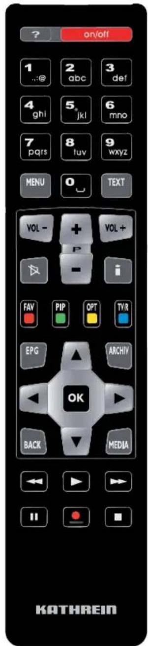
■ Remote control RC 674
■ Safety instructions (multi-lingual)
■ HDMI cable
■ HD+ flyer
The accessories supplied may differ in appearance from those illustrated!

natural_image
Black USB cable with two connectors, no text or symbols visibleSmartcard

Batteries
Remote ControlHDMI cable
Connection and setup
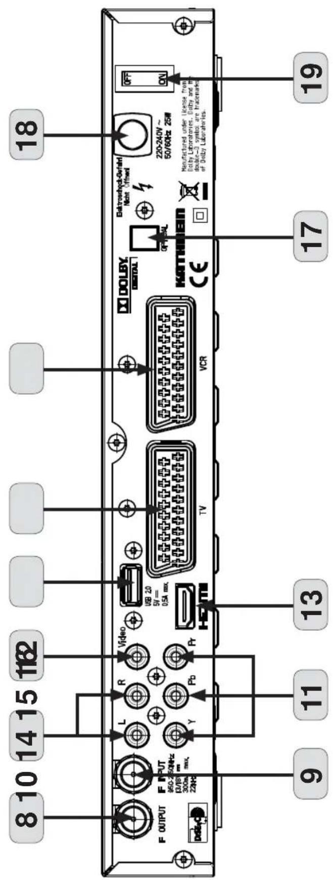
Front/rear view of the receiver (front fl ap open)

Connection and setup
Front:
- On/Off (operation/stand-by)
- 4-character numeric display
- Channel selection button (-)
- Channel selection button (+)
- Card reader (Nagravision integrated - for HD+ card)
- Common Interface for one (CI+) CA module for Pay-TV cards *)
7 Button for ejecting the CA module
Rear view:
- LNB loop-through input
- LNB input
- Audio outputs (L/R) - cinch sockets
- 3 x Cinch connections for component outputs YUV labelled = Y/Pb/Pr
- Video output (composite colour)
- HDMI connection
- USB 2.0 port (USB-A connector)
- Scart socket for TV connection
- Scart socket for VCR/AUX connection
- Optical data stream output (SPDIF/Sony Philips Digital Interface Format) for Dolby Digital AC 3 audio
- Mains power cable
- On/Off switch **
*) CA modules and smartcards are not included with this product **) The unit is not fully disconnected from the mains (see the sections “Safety Instructions - Important Instructions” and “Periods of extended absence, thunderstorms, mains socket accessibility”)
Connection and setup
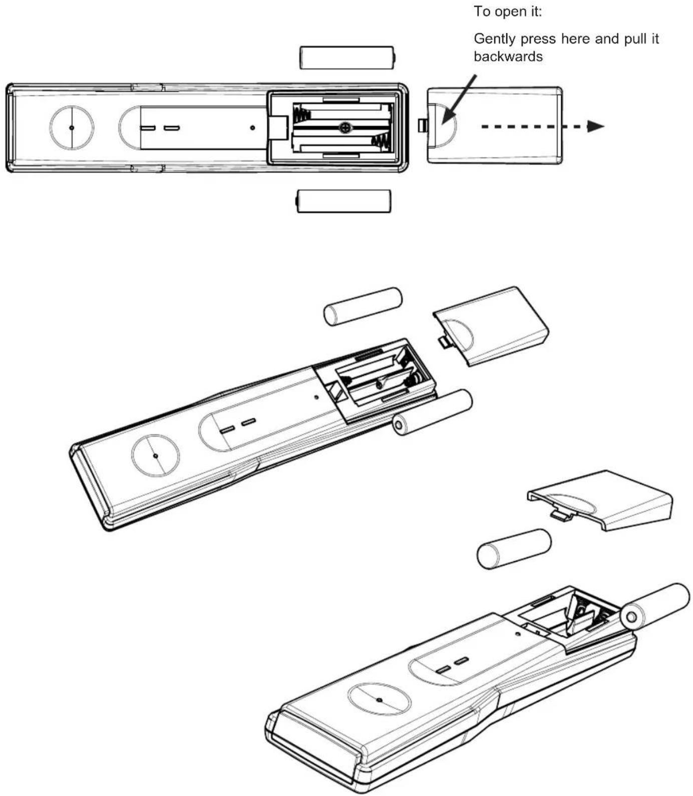
Inserting batteries into the remote control
Remove the cover on the rear of the remote control. Insert the two batteries supplied into the remote control. Ensure correct polarity of the batteries; the + and - markings as indicated inside the battery compartment. Slide the cover back onto the housing until it locks in place.
Connection and setup
Connecting the receiver

If you do not know the configuration of your satellite reception system, contact your specialist dealer.
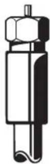
Connect the Sat IF inputs on the receiver to the satellite reception system. Use coaxial cable with an F standard connector (see illustration on right).
Conventional DiSEqC™ system

TV connection
Connect the satellite receiver (HDMI or alternatively TV Scart socket) and the TV set using a HDMI or Scart cable (see the connection example above).
Connection and setup
Audio connection
Digital
There are two ways you can access the digital audio.
HDMI
The stereo audio is transmitted to your TV set via the HDMI interface. If your TV set also supports Dolby Digital, you can also receive the Dolby Digital audio via the HDMI interface (providing it is broadcast by the channel provider). On this issue refer to the operating manual for your TV set.
SPDIF Dolby Digital output (optical)
The SPDIF outputs are intended for the connection of a Dolby Digital system (see “Advanced connection example” in the technical appendix). Connect the SPDIF output (electrical or optical) to the Dolby Digital system using an appropriate cable.
Analogue
If you want to play the sound on your hi-fi system, connect the audio cinch sockets to the input sockets on the hi-fi system, using an appropriate cable (see "Advanced connection example" in the technical appendix).
Connecting up the Video/DVD recorder
Use a Scart cable to connect the satellite receiver (VCR Scart socket) to the video recorder/PVR. To play back a DVD, i.e. output the signal from the PVR through the receiver on the TV set, the TV set must also be connected to the receiver with a Scart cable. This is necessary because the video signal from the VCR Scart socket of the receiver is not looped through / forwarded to the HDMI output of the receiver.
Tipp!
If you are recording via an external video recorder/DVD, remember not to operate the receiver during recording, otherwise all the on-screen displays will appear on your recording.
Connection and setup
First Installation

Before you start to use the UFS 932, read the sections "Safety Instructions - Important Instructions", "Important Information" and "Connection and Set-Up" through to the item "First Installation".
Do not connect the unit to the mains until all installation work has been properly carried out.
The guidance provided in the “First Installation” section assumes that the receiver has been properly connected as per the “Safety Instructions - Important Information” and “Connection and Set-Up” chapters through to the “First Installation” section.
Required buttons on remote control for first installation:
 | Numeric entry |  | Proceed to the next step in the first installation |
 | Go back one step in the first installation |  | Confirm the changed values/ setting; call up the submenus |
 | Select/change individual menu parameters, navigation | ||
 | Cancel entry, go back |
First switch your TV set on and select the AV-/HDMI input you have used to connect the receiver to your TV set. Switch on the receiver at the power switch on the rear of the unit. Undertake the first installation. If you have any questions or encounter problems, contact your specialist dealer.
The following on-screen display appears:
Tipp!
Always pay attention to the bar at the bottom of the on-screen display. This provides information on what to do next.

Use the ▲▼ buttons to select the desired menu language for your UFS 932 and confirm your selection using the OK button.
Connection and setup
The following languages are available: German, English, French, Italian, Spanish, Czech, Dutch, Polish, Turkish and Russian.
Press the PIP (green) button to move to the next menu.
The following on-screen display appears:
Here you can use the 🧑 buttons to select the correct local time setting (e.g. “Berlin” for Germany).

Press the PIP (green) button to move to the next menu.
Use the 📁 buttons here to select the basic settings for the video output from the receiver to the TV set.

For this, refer to the operating manual for your TV set and take care to select only those settings that your TV set can process.

Resolution (HDMI/YUV format)
Here you can select the video resolution that will be output at the TV set. Either
- 1080p (resolution 1920 x 1080, full-screen images)
- 1080i (resolution 1920 x 1080, half-screen images)
- 720p (resolution 1280 x 720, full-screen images)
- 576p (resolution 720 x 576, full-screen images)
- 576i (resolution 720 x 576, half-screen images)
- 480p (resolution 640 x 480, full-screen images)
- 480i (resolution 640 x 480, half-screen images)

No recording can be performed at video resolution 1080p.
This resolution can "only" be used for viewing the live signal.
TV Mode
This setting depends on the resolution previously selected and is performed automatically by the receiver.
Connection and setup
TV Aspect Ratio
Here you can select the TV picture format. Either
- 4:3,
- 16:9 or
- Auto
Scaling Method
Here you can select the screen display mode:
- TV Scale The format transmitted by the programme provider is used
- Letterbox: The picture is reduced to suit the TV screen (there may be black bands above and below it)
- Pan & Scan: Zoomed in
- Zoom: Stretched (full screen)
HDCP Enabled
Here you can select whether HDCP (digital copy protection) is set to "On" at all times, or is "Off" - not activated.

ew some programmes it may be necessary for the setting to be set to "On".
Video Output
Here you can select whether the receiver will output the RGB signal at the Scart sockets - selection "RGB" (Red/Green/Blue signal). If the setting "RGB" is selected, no TV signal can be output at the YPbPr sockets.

Important instruction for picture output using the "YPbPr" sockets:
If you TV set is connected to the receiver using the YPbPr sockets, it is essential that the video output setting "YPbPr" is selected.
Press the PIP (green) button to move to the next menu.
Connection and setup
The following on-screen display appears:

The settings for the tuner confi guration should be performed by a specialist engineer for this reception system.

Tipp!
If your receiver is connected as in the connection example (see “Connecting the receiver” in this section), no changes are necessary for the remainder of the first installation. If you are not familiar with the details of your reception system, note the following:
In many cases the satellite reception system is a DiSEqC TM 1.0 system. This type of system is preset.
Confirm the rest of the on-screen displays during the first installation using the (green) button. You cannot damage your reception system during this process! If you do not receive a TV picture at the end of the first installation, contact your specialist dealer.

You should perform the antenna configuration / make changes yourself only if you are fully familiar with the particulars of your reception system.
The individual items are selected using the ▲▼ buttons. If you need to access sub-menus, they can be called up using the OK button. The changes to the current settings can be performed using the buttons or the number pad.
You can set up the antenna (tuner) configuration for the following types of reception systems:
- LNB only
- DiSEqC™1.0
- Unicable
Continue as described in the initial installation for the type of reception you have selected.
Connection and setup
LNB only

Select Satellite
Use the ▶▶ buttons here to select the satellite whose signal is present at the tuner.
LNB Type
If your reception system does not have a Universal LNB, use the ▶ buttons to select the LNB types that are used in your reception system. You can choose from the following LNB types:
- Universal 1
- Broadband
- User or
- Standard

Refer to the documentation for your LNB or seek assistance from a specialist engineer.
Low Oscillation Frequency (LNB low frequency)
You only need to specify this data if your LNB type is not "Universal LNB". For this, refer to the documentation supplied with your LNB. Enter the LNB low frequency, using the numeric pad or the ▶ buttons.
High Oscillation Frequency (LNB high frequency)
You only need to specify this data if your LNB type is not "Universal LNB". Enter the LNB high frequency, using the numeric pad or the ▶ buttons.
22 kHz
This cannot be set and is not required
Connection and setup
LNB Power
This is factory-set to "On", but must be changed if your LNB has its own power supply. In most cases the LNB power supply is provided by the receiver.
(Test) transponder (TP)
Select the selection field "TP". Here you can select a transponder for checking whether your settings are correct using the signal strength bar and signal quality bar.
When you have completed all settings, press the (green) button.
You will automatically be shown the display for "Update LCN List". Continue the first installation with the "Update LCN List" selection.
Connection and setup
DiSEqC™1.0

bar
First Installation 4/5 Antenna Configuration | System | DiSEqC 1.0 | | :--- | :--- | | Satellite | ASTRA 19.2E | | Port | 1 | | TP | 69.12421 /H/27500 | Signal Strength: 100% Signal Quality: 89% Press to change to the required one Cancel Back Forward to the next stepSelect satellite and port (satellite slot)
Here you can select the satellites whose signals you wish to receive. Select only those satellites that are present in the signal at the tuner. You can set up a maximum of four satellites.
First use the ▶▶ buttons in the "Satellite" line to select the desired satellite, then in the "Port" line assign it the position "1" in the sequence of your satellites.
If you wish your system to receive signals from more than one satellite, switch back to the "Satellite" and select a second satellite. Then in the "Port" line assign this satellite the position "2" in the sequence.
Repeat this procedure until you have set up all the satellites whose signals you wish to receive.
(Test) transponder (TP)
Select the selection field "TP". Here you can select a transponder for checking whether your settings are correct using the signal strength bar and signal quality bar.
When you have completed all settings, press the 📄 (green) button.
You will automatically be shown the display for "Update LCN List". Continue the first installation with the "Update LCN List" selection.
Connection and setup
Single Cable System

If you use a UAS 481 (single cable LNB) in your reception system, you are only allowed to select one satellite.

Select satellite and port (satellite slot)
Here you can select the satellites whose signals you wish to receive. Select only those satellites that are present in the signal at the tuner. You can set up a maximum of two satellites.
First use the ▶▶ buttons in the "Satellite" line to select the desired satellite, then in the "Port" line assign it the position "1".
If you wish your system to receive signals from a second satellite, switch back to the "Satellite" and select the second satellite. Then in the "Port" line assign this satellite the position "2" in the sequence.

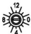
When setting of the assigned User Band (transmission channel) and the User Band Frequency (transmission frequency), please refer to the documentation supplied with your system. You will find there a printed list showing the assignment between the various transmission channels and the respective transmission frequencies. Please note also that multiple receivers cannot share the same frequencies / channels - the receivers would interfere with each other.
User Band (transmission channel)
Select a free available transmission channel (1-8).
User Band Frequency (frequency of the transmission channel)
Select here one of the free available transmission frequencies or use the numeric pad to input the required frequency.
See example on the right (EXR 1581) for assignment of a transmission channel to a transmission frequency.


| SCR(0) = 1284 MHz |
| SCR(1) = 1400 MHz |
| SCR(2) = 1516 MHz |
| SCR(3) = 1632 MHz |
| SCR(4) = 1748 MHz |
| SCR(5) = 1864 MHz |
| SCR(6) = 1980 MHz |
| SCR(7) = 2096 MHz |
ATTENUATION
Connection and setup
(Test) transponder (TP)
Select the selection field "TP". Here you can select a transponder for checking whether your settings are correct using the signal strength bar and signal quality bar.
When you have completed all settings, press the ☐ (green) button.
You will automatically be shown the display for "Update LCN List". Continue the first installation with the "Update LCN List" selection.
Update LCN list
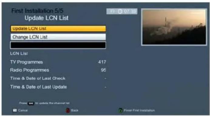
Select here whether you wish to use the channel list presorted in the factory (Update LCN List) or a channel list presorted for a specific country (Change LCN List).
Update LCN List
Press the OK button to load a channel list presorted in the factory.
Change LCN List
Press the OK button to view the available channel lists, presorted for the respective country. Select the desired channel list and confirm your selection by pressing the OK button. During the loading procedure for the channel list the following display may appear:
Confirm with the BACK button.
No new services found

As soon as the receiver has finished loading the channel list you can press the ☐ (green) button to close the first installation.
Connection and setup
Common Interface (CI)

Always follow the operating instructions from your Pay-TV provider and the instructions supplied with the Smartcard and the CA (Conditional Access) module!
Smart cards and CA modules are not included with this product!
The cards and modules are issued by the respective pay TV providers, and contain the subscriber data and details of the channels for which the subscriber has paid. These channels are always scrambled.
Contact the Pay TV provider if you are interested in subscribing to a particular Pay TV channel.
You are responsible for the use of the smart card in the CA!
The smart card sold by the Pay TV provider, specific to a particular encryption technology, is inserted into the CA module.
Store your card and PIN code securely when not in use!
Inserting the HD+ card in the smart card reader

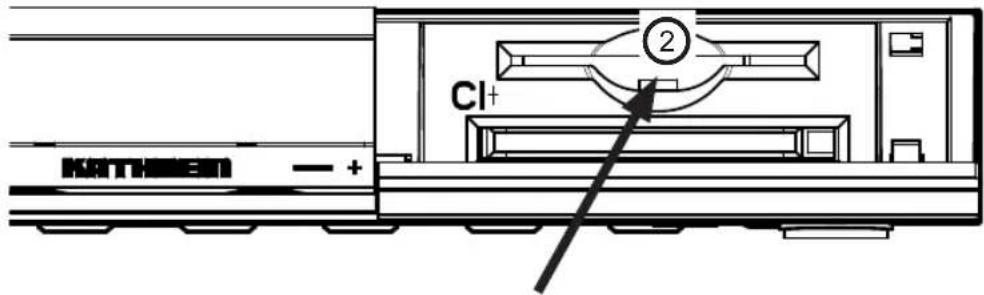
The smart card reader (small slot) ② on the UFS 932 (Nagravision embedded) is intended to be used for the HD+ card. The smart card reader is behind the flap on right on the front underneath the Common Interface (large slot). It must be possible to insert the smart card (chip contacts pointing down) in the smart card reader without the need for a large amount of force. Do not use excessive force and pay attention to the manual supplied with the smart card.
Connection and setup
Inserting the smart card and the CA module
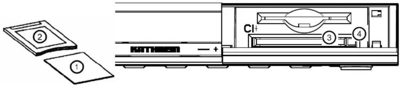
Inserting the CA module into the CI
The Common Interface (CI+) ③ of the UFS 932 is suitable for insertion of a CI+ module (or CA module) and is located on the front panel of the receiver (behind the flap). The CA module ② accepts the smart card ①
(chip contacts pointing downwards and towards socket strip) and is then inserted in the CI+ slot ③. The smart card should be inserted into the CI+ or CA module without exerting excessive force. The same applies to inserting the CI+ or CA module into the CI+ slot.
Do not use without excessive force, and follow the instructions supplied with the Smartcard and the CI+ or CA module. To remove the CI+ or CA module, press the ejection button④ and pull it out straight backwards.
Troubleshooting
In the event of a malfunction, first check all the cable connections and operating states:
- Receiver and TV set power plugs are connected to wall socket
- Antenna cables are connected to the receiver input
- Receiver and TV set correctly connected by a HDMI or Scart cable
- Audio connections are made to the Hi-Fi or Dolby Digital system as appropriate
- Receiver and TV set (Hi-Fi/Dolby Digital system) are switched on (check power indicators)
- Receiver is responding to remote control
A selection of troubleshooting tips is offered below.
| Problem Cause Remedy | ||
| A “No signal!” warning appears on some or all channels | Consult an antenna specialist to have it checked and repaired as necessary. Check the settings performed in the “Settings”, “Antenna & Satellite”, “Tuner-Confi guration” menu, and change them if necessary. | |
| Remote control no longer responds | The batteries may be flat or inserted incorrectly into the battery compartment. | Check the batteries (see also “Inserting batteries into the remote control” in these instructions) |
| Wrong time is displayed | The “Summertime” setting is wrong. An incorrect time was imported from the reception signal | Check the “Local Time Setting” in the “System Setup” menu, and change it if necessary. Use the power switch to switch the receiver off from the current channel, e.g. Das Erste or ZDF, wait 10 seconds and then switch it back on |
| The following channels cut out, or “No or bad signal!” appears: Sport 1, Tele 5, HSE 24 and Sonnenklar TV | DECT telephones operate on the same frequency as these channels. Interference may occur due to inadequate level or poor shielding of cable | Consult your antenna specialist |
Service
If, despite studying this operating manual, you still have questions about getting started with the unit or using it correctly, or if unexpected problems occur, please contact your specialist dealer. The Kathrein customer hotline is also at your disposal.
Tel: 0900/1122240 *
* (0.49 EUR per minute on Deutsche Telekom AG land lines, calls from mobile phones may cost more)
Technical appendix
Advanced connection example

Technical appendix
Technical Specifications
| Type UFS 932si/HD+ UFS 932sw/HD+ | |||
| Order no./colour 20210188/silver 20210189/black | |||
| RF section | |||
| Sat IF band MHz 950-2150 | |||
| Input level band dBμV 44-83 | |||
| TV system, video | |||
| Modulation, FEC, demultiplexer | DVB-S-/DVB-S2 standard | ||
| Video resolution | CCIR 601 (720 x 576 lines), 576i, 576p, 720p, 1080i, 1080p | ||
| Video decryption | MPEG-2, MPEG-4-compatible | ||
| Input data rate | MSymb/s | 2-45 (30 for DVB-S2/8PSK) | |
| S/N | dB | ≥ 53 | |
| TV system, audio | |||
| Decryption AC 3, MPEG 1, layers 1 and 2 | |||
| Sampling rate | kHz | 32/44,1/48 | |
| S/N | dB | ≥ 65 | |
| Power Supply | |||
| Power supply voltage | V/Hz | 230 (+/- 10 %)/50-60 | |
| Power consumption (max./typ. operation/standby) | W | < 25/12/1 | |
| LNB supply (horiz./vert.) | V/mA | 14/18; max. 350 | |
| Control signal | kHz | 22; DiSEqCTM1.0, SCR single-cable system | |
| Connections | |||
| Sat IF input/output | 2 x F socket | ||
| TV/VCR connection | 2 x Scart sockets | ||
| Video output (analogue) | 3 x Cinch socket (YPbPr)/1 x Cinch socket | ||
| Video/audio output (digital) | 1 x HDMI | ||
| Audio output (analogue) | 2 x Cinch sockets | ||
| Audio output (digital) | Standard fibre-optic cable (SPDIF) | ||
| Data interface | |||
| Common Interface/encryption system | For 1 Cl+ or CI module/Nagravision | ||
| USB | 1 x 2.0 | ||
| General information | |||
| Ambient temperature | °C | Max. +5 to +40 | |
| Unit dimensions (W x H x D)/weight | mm/kg | 210 x 40 x 310/< 2 | |
Technical appendix
Sat IF connection examples
Individual reception systems
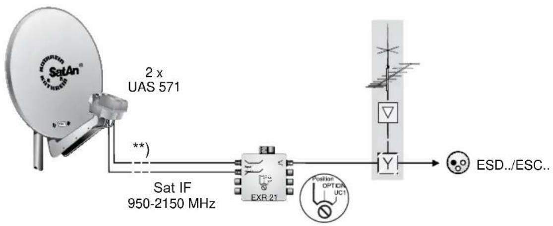
flowchart
graph LR
    A["SatAn®"] -->|2 x UAS 571| B["Sat IF 950-2150 MHz"]
    B --> C["EXR 21"]
    C --> D["Y"]
    D --> E["ESD../ESC.."]
    F["Position OPTION UC1"] --> C
    G["**"] --> B
Community antenna network systems (4 x Sat IF)


Technical appendix
Community antenna network systems (8 x Sat IF), multi-feed
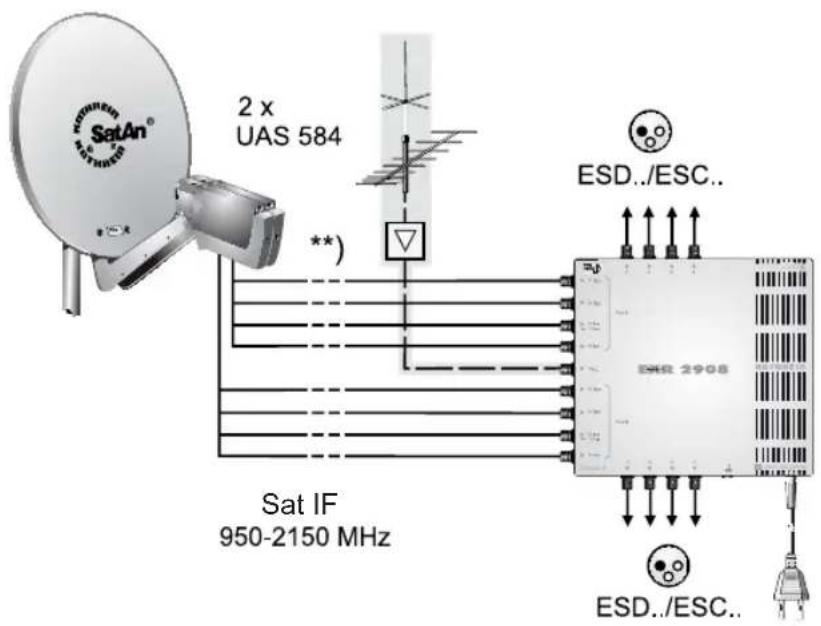
Community antenna network systems (16 x Sat IF), multi-feed
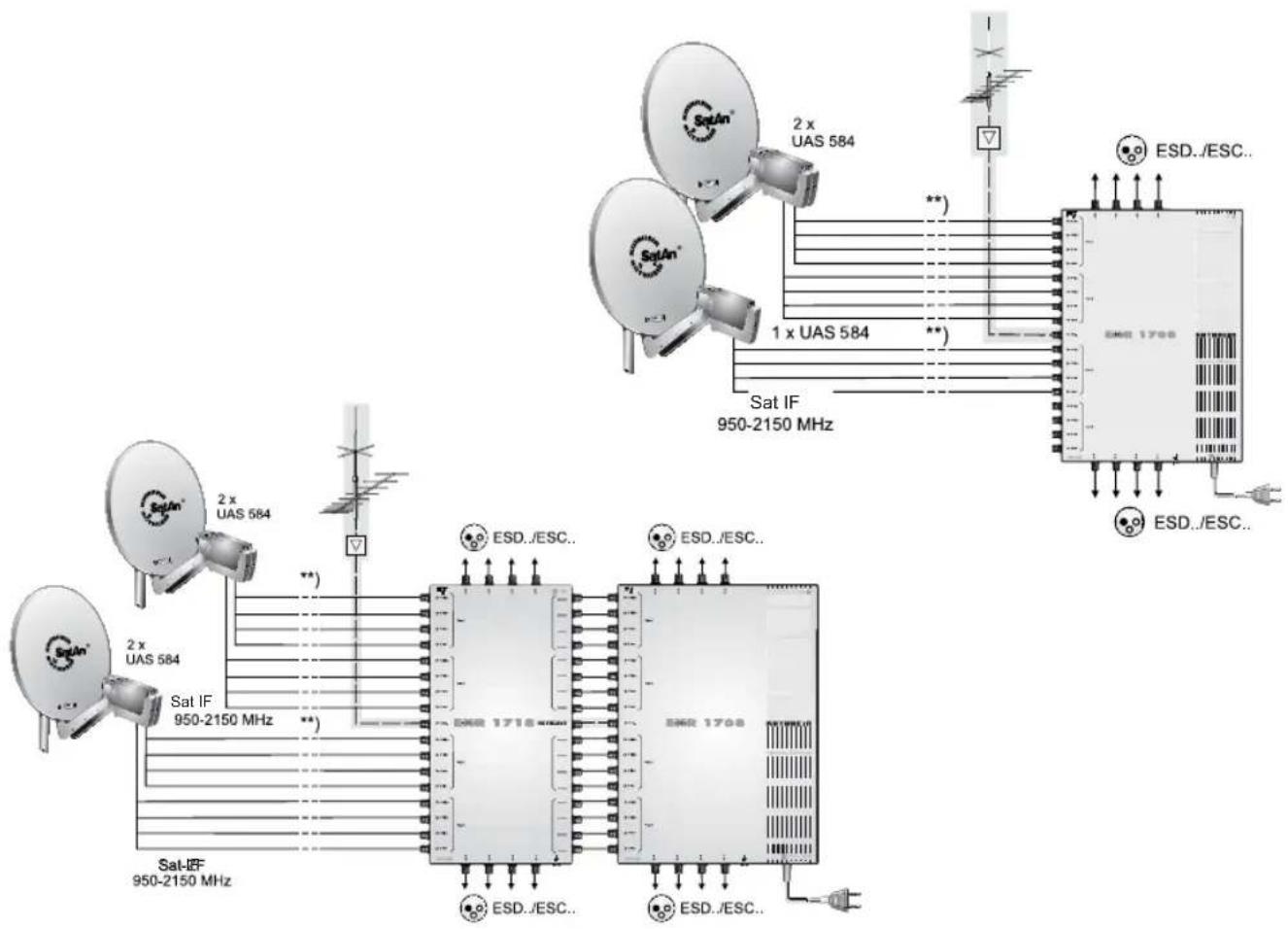
flowchart
Satellite network architecture diagram showing connections between Satellite 950-2150 MHz, Satellite 950-2150 MHz, and Satellite 1700 with satellite dishes and ESD.ESC. components.Technical appendix
Single cable systems
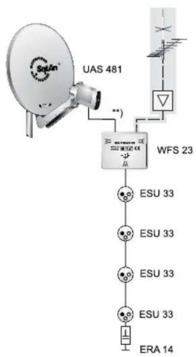
flowchart
graph TD
    A["UAS 481"] -->|**| B["WFS 23"]
    B --> C["ESU 33"]
    B --> D["ESU 33"]
    B --> E["ESU 33"]
    B --> F["ERA 14"]

flowchart
graph TD
    A["UAS 481"] -->|**| B["WFS 23"]
    B --> C["EBC 10"]
    C --> D["4 x ESU 33"]
    C --> E["ERA 14"]
    C --> F["ERA 14"]

flowchart
graph TD
    A["UAS 584/585 Satellite"] -->|**| B["Sat IF 950-2150 MHz"]
    B --> C["EBR 2542"]
    B --> D["EBR 1542"]
    C --> E["EBC 10"]
    D --> F["EBC 10"]
    E --> G["Single: ESU 33"]
    E --> H["Single: ESU 33"]
    E --> I["ERA 14"]
    F --> J["Single: ESU 33"]
    F --> K["Single: ESU 33"]
    F --> L["ERA 14"]
    C --> M["Twin: ESU 33"]
    C --> N["Twin: ESU 33"]
    C --> O["Twin: ESU 33"]
    D --> P["Twin: ESU 33"]
    D --> Q["Twin: ESU 33"]
    D --> R["Twin: ESU 33"]
    C --> S["ERA 14"]
    D --> T["ERA 14"]
    style A fill:#f9f,stroke:#333
    style B fill:#ccf,stroke:#333
    style C fill:#cfc,stroke:#333
    style D fill:#cfc,stroke:#333
    style E fill:#fcc,stroke:#333
    style F fill:#fcc,stroke:#333
    style G fill:#ffc,stroke:#333
    style H fill:#ffc,stroke:#333
    style I fill:#ffc,stroke:#333
    style J fill:#ffc,stroke:#333
    style K fill:#ffc,stroke:#333
    style L fill:#ffc,stroke:#333
    style M fill:#ffc,stroke:#333
    style N fill:#ffc,stroke:#333
    style O fill:#ffc,stroke:#333
    style P fill:#ffc,stroke:#333
    style Q fill:#ffc,stroke:#333
Technical appendix

flowchart
graph TD
    A["UAS 584/585"] -->|**| B["Sat IF 950-2150 MHz"]
    C["EKR 1581"] --> D["EBC 10"]
    D --> E["ESU 33"]
    E --> F["Twin"]
    E --> G["Twin"]
    E --> H["ERA 14"]
    I["UAS 584/585"] --> J["Sat IF 950-2150 MHz"]
    K["EKR 2558"] --> L["ESD../ESC.."]
    M["EKR 2581"] --> N["ESD../ESC.."]
    O["EBR 10"] --> P["ESU 33"]
    P --> Q["Twin"]
    P --> R["Twin"]
    P --> S["ERA 14"]
    T["ESU 33"] --> U["Twin"]
    V["ESU 33"] --> W["Twin"]
    X["ESU 33"] --> Y["Twin"]
    Z["ESU 33"] --> AA["Twin"]
    AB["ERA 14"] --> AC["Twin"]
    AD["ESU 33"] --> AE["Twin"]
    AF["ESU 33"] --> AG["Twin"]
    AH["ERA 14"] --> AI["Twin"]
    AJ["ESU 33"] --> AK["Twin"]
    AL["ESU 33"] --> AM["Twin"]
    AN["ESU 33"] --> AO["Twin"]
    AP["ESU 33"] --> AQ["Twin"]
    AR["ESU 33"] --> AS["Twin"]
    AT["ESU 33"] --> AU["Twin"]
    AV["ESU 33"] --> AW["Twin"]
    AX["ESU 33"] --> AY["Twin"]
    AZ["ESU 33"] --> BA["Twin"]
    BB["ESU 33"] --> BC["Twin"]
    BD["ESU 33"] --> BE["Twin"]
    BF["ESU 33"] --> BG["Twin"]
    BH["ESU 33"] --> BI["Twin"]
    BJ["ESU 33"] --> BK["Twin"]
    BL["ESU 33"] --> BM["Twin"]
    BN["ESU 33"] --> BO["Twin"]
    BP["ESU 33"] --> BQ["Twin"]
    BR["ESU 33"] --> BS["Twin"]
    BT["ESU 33"] --> BU["Twin"]
    BV["ESU 33"] --> BW["Twin"]
    BX["ESU 33"] --> BY["Twin"]
    BZ["ESU 33"] --> CA["Twin"]
    CB["ESU 33"] --> CC["Twin"]
    CD["ESU 33"] --> CE["Twin"]
    CF["ESU 33"] --> CG["Twin"]
    CH["ESU 33"] --> CI["Twin"]
    CJ["ESU 33"] --> CK["Twin"]
    CL["ESU 33"] --> CM["Twin"]
    CN["ESU 33"] --> CO["Twin"]
    CP["ESU 33"] --> CE
    CO --> CE
    CE --> CE
    CE --> CE
    CE --> CE
    CE --> CE
    CE --> CE
    CE --> CE
    CE --> CE
    CE --> CE
    CE --> CE
    CE --> CE
    CE --> CE
    CE --> CE
    CE --> CE
    CE --> CE
    CE --> CE
    CE --> CE
    CE --> CE
    CE --> CE
    CE --> CE
    CE --> CE
    CS["Sat IF 950-2150 MHz"] --> CS
    CS --> CS1["Sat IF"]
    CS1 --> CS2["Sat IF"]
For your notes
For your notes



- Operating instructions part 1 UFS 932 Connection and Setup
- English
- Safety Instructions – Important Notes.... 2
- Scope of supply 5
- Connection and setup....6
- Troubleshooting 22
- Service....23
- Technical appendix 24
- Safety Instructions – Important Notes
- Mains cable
- Cleaning
- Playing children
- Earthing
- Power supply voltage
- Moisture, direct sunlight, heat, naked flames
- Batteries
- Ventilation
- Repairs
- Connections
- Periods of extended absence, thunderstorms, mains socket accessibility
- Installation location
- Spent batteries are special waste!
- Product return/original packaging
- Ventilation slots on the unit
- Switching the receiver off
- Miscellaneous
- Scope of supply
- Connection and setup
- Front:
- Rear view:
- Inserting batteries into the remote control
- Connecting the receiver
- TV connection
- Audio connection
- Digital
- HDMI
- SPDIF Dolby Digital output (optical)
- Analogue
- Connecting up the Video/DVD recorder
- Tipp!
- First Installation
- Resolution (HDMI/YUV format)
- TV Mode
- TV Aspect Ratio
- Scaling Method
- HDCP Enabled
- Video Output
- LNB only
- Select Satellite
- LNB Type
- Low Oscillation Frequency (LNB low frequency)
- High Oscillation Frequency (LNB high frequency)
- kHz
- LNB Power
- (Test) transponder (TP)
- DiSEqC™1.0
- Select satellite and port (satellite slot)
- Single Cable System
- User Band (transmission channel)
- User Band Frequency (frequency of the transmission channel)
- Update LCN list
- Change LCN List
- Common Interface (CI)
- Inserting the HD+ card in the smart card reader
- Inserting the smart card and the CA module
- Inserting the CA module into the CI
- Troubleshooting
- In the event of a malfunction, first check all the cable connections and operating states:
- Service
- Technical appendix
- Sat IF connection examples
- For your notes
Brand : KATHREIN
Model : UFS 932sw
Category : Receiver