
MWP-20 - Fan MPM - Free user manual and instructions
Find the device manual for free MWP-20 MPM in PDF.


| Product Type | Floor fan with ultrasonic humidifier |
| Brand | MPM |
| Model | MWP-20 |
| Fan Power | 52.1 W |
| Maximum Airflow | 59.3 m³/min |
| Maximum Air Speed | 3.1 m/s |
| Sound Power Level | 57 dB(A) |
| Standby Power Consumption | 0 W |
| Seasonal Electricity Consumption | 16.7 kWh/a |
| Water Tank Capacity | 3.2 L |
| Timer | 0–60 minutes |
| Speed Settings | 3 speeds (low, medium, high) |
| Oscillation | Yes, manual on/off button |
| Adjustable Blow Angle | Yes, via screw |
| Humidifier Type | Ultrasonic with adjustable mist intensity |
| Power Cord Length | 1.70 m |
| Assembly Required | Yes, includes base, pipes, propeller covers, water tank |
| Cleaning | Weekly cleaning of water tank and internal container; use mild detergent |
| Safety Features | Overheat protection not specified; requires grounding; do not use outdoors |
| Warranty | Contact manufacturer: MPM AGD S.A. |
Frequently Asked Questions - MWP-20 MPM
User questions about MWP-20 MPM
0 question about this device. Answer the ones you know or ask your own.
Ask a new question about this device
Download the instructions for your Fan in PDF format for free! Find your manual MWP-20 - MPM and take your electronic device back in hand. On this page are published all the documents necessary for the use of your device. MWP-20 by MPM.
USER MANUAL MWP-20 MPM
natural_image
Modern outdoor fan with blue and silver casing, mounted on a stand (no visible text or symbols)WENTYLATOR Z FUNKCJĄ NAWILŻANIA MWP-20
natural_image
Close-up of a metallic circular component with small holes, possibly a filter or sensor array (no visible text or symbols)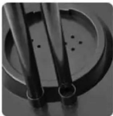
natural_image
Close-up of two cylindrical metal pipes with circular base and perforated surface (no text or symbols visible)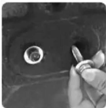
natural_image
Close-up of a hand holding a small object with a circular hole, possibly a mechanical part or fixture (no visible text or symbols)obr. 1
natural_image
Three-panel black-and-white photo showing a hand adjusting a cable with a hose, inside a vehicle charging station (no visible text or symbols)obr.2
natural_image
Close-up of a hand holding a dark circular object with radial lines, next to a fan-shaped grille (no text or symbols visible)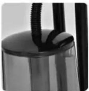
natural_image
Close-up of a black cylindrical object with two protruding rods, possibly a lamp or fixture (no visible text or symbols)obr. 7
natural_image
Diagram of a mechanical component with a downward arrow indicating motion or force (no text or symbols present)obr. 5
natural_image
Mechanical assembly diagram showing a rotating component with a downward arrow indicating motion (no text or symbols)obr. 6
NAPLNĚNÍ NÁDRŽKY NA VODU
natural_image
Simple line drawing of a cylindrical container with a side panel and a rotating knob, no text or symbols present.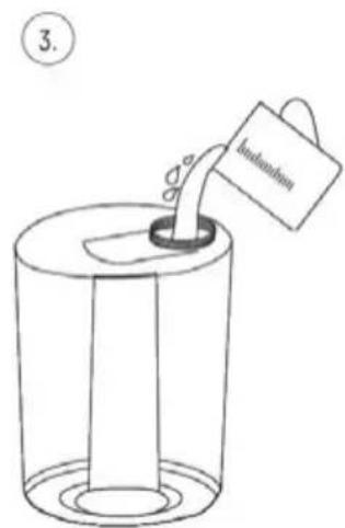
natural_image
Simple line drawing of a cylindrical container with a side knob and a small mechanical component (no text or symbols)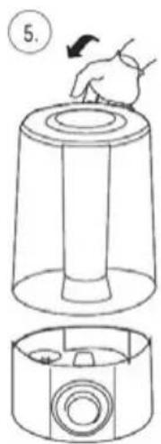
NAPLNĚNÍ NÁDRŽKY NA VODU
POUŽITÍ ZAŘÍZENÍ
natural_image
Close-up of a petri dish with visible colonies, no text or symbols present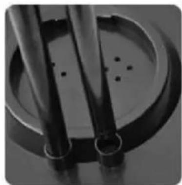
natural_image
Close-up of two metallic pipes mounted on a circular base with small holes, no visible text or symbols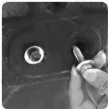
natural_image
Close-up of a hand holding a small metallic object, possibly a tool or component, with no visible text or symbols.Abb. 1
natural_image
Close-up of a hand using a tool to connect a cable to a car interior, with a magnified inset showing the close-up of the cable being held.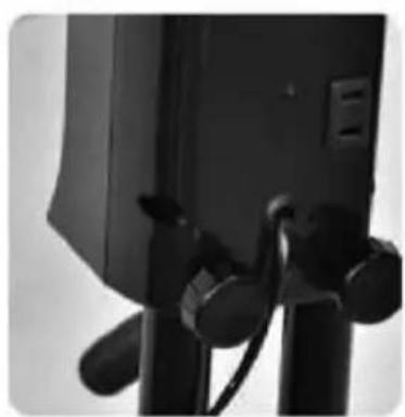
natural_image
Close-up of a black camera module with attached cables and a small panel, no visible text or symbolsAbb. 2
natural_image
Close-up of a mechanical component with a circular fan-like pattern and a hand adjusting it (no visible text or symbols)Abb. 3
natural_image
Close-up of a person using a medical CT scanner to interact with an eye (no visible text or symbols)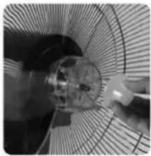
natural_image
Close-up of a mechanical fan or fan with a metallic component and a tool, no visible text or symbolsnatural_image
Close-up of hands holding a circular fan with mesh grille (no visible text or symbols)Abb. 4
natural_image
Close-up of a wire mesh fan or fan structure with no visible text or symbolsnatural_image
Close-up of a hand holding a dark fan blade, no visible text or symbolsAbb. 7
natural_image
Close-up of a cylindrical object with black and white wires, possibly a lamp or fixture (no visible text or symbols)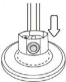
natural_image
Diagram of a mechanical component with a downward arrow indicating motion or force (no text or symbols present)Abb. 5
natural_image
Mechanical assembly diagram showing a rotating component with a downward arrow indicating motion (no text or symbols)Abb. 6
FÜLLEN DES WASSERBEHÄLTERS
natural_image
Simple line drawing of a cylindrical container with a side knob and a rotating knob (no text or symbols)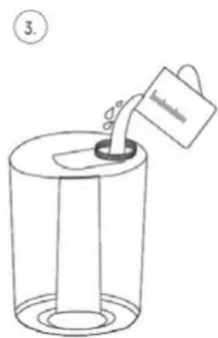
natural_image
Simple line drawing of a cylindrical container with a side knob and a small mechanical component, no text or symbols present.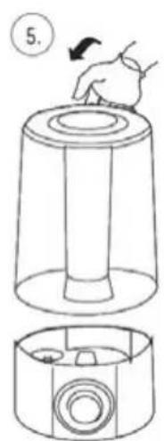
natural_image
Mechanical assembly diagram showing a fan blade and internal mesh structure (no text or symbols)natural_image
Close-up of a black office fan with mesh grille and directional arrow indicator (no text or symbols)INSTRUCTIONS ASSOCIATED WITH USE SAFETY
Read carefully this manual before using the appliance.
- Close supervision is necessary when using the appliance near children.
Do not hang the power cord over sharp edges and do not allow the power cord to touch hot surfaces.
▶ Always unplug the appliance when it is not in use or before cleaning.
Do not use the appliance if it is damaged, also if the power cord or plug is damaged - return the appliance for repair to an authorized service centre.
To avoid the risk of damage or injury, always use the attachments recommended by the manufacturer.
Do not immerse the appliance, its cord and plug in water or any other liquids, keep it dry at all times.
Do not leave the appliance switched on when unattended.
▶ Always switch off the appliance before unplugging it.
Do not place the appliance in vicinity of heat sources.
Do not use the appliance for the purposes different than it was designed for.
Do not use the appliance outdoors.
Never insert your fingers nor any other items through the guard when the appliance is running.
Before moving the appliance to another location disconnect it from the power source.
Do not cover the front and rear guard!
Do not place the fan near open windows - raindrops may cause a short circuit and electrical shock! It is advisable not to place fans in rooms with high humidity, such as bathrooms.
This appliance is not intended for use by children under 8 years of age and individuals with reduced physical, sensory or mental capabilities, or lack of experience and knowledge, unless they have been given supervision or instruction concerning use of the appliance in a safe way and if they understand the hazards involved. Cleaning and user maintenance shall not be carried out by children without supervision.
- Store the appliance and its cord out of reach of children under 8 years of age.
Children should be supervised to ensure that they do not play with the appliance.
Do not switch on the appliance without front and rear guard mounted.
The appliance may be switched on only after complete assembly. Partially assembled unit does not provide safe and proper operation.
Do not plug the power cord with wet hands.
This appliance is intended for household use only.
Place the appliance on a dry, flat and stable surface.
The appliance is not intended to be operated by means of an external timer or separate remote-control system.
Do not place the appliance on hot surfaces.
Do not place the appliance in vicinity of electric and gas cookers, burners, ovens, etc.
Do not place the appliance against a wall or against other appliances. Leave at least 20 cm of free space on the back and sides and above the appliance. Do not place anything on top of the appliance.
Do not touch the appliance, power cord, or power plug with wet hands.
Long hair can be caught in the fan owing to the air turbulence. Hair, jewelry, and loose clothing must be kept
away from the fan.
Do not remove the plug from the mains by pulling by the cord.
In order to ensure your children's safety, please keep all packaging (plastic bags, boxes, polystyrene etc.) out of their reach.
WARNING! Do not allow small children to play with the foil as there is a danger of suffocation!
The appliance should be connected into the socket with grounding pin.
- Do not add any chemical agents to the water poured into the tank - they can seriously damage the device.
Do not pour water directly into the mist sprayer or its tube.
Unplug the power cord from the mains before adding water.
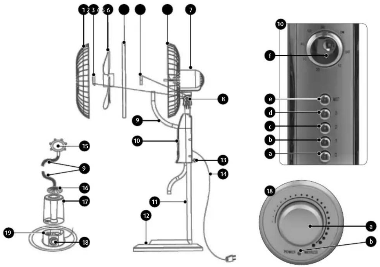
- Front propeller cover
- Propeller nut
- Propeller
- Cover ring
- Rear propeller cover cap nut
- Rear propeller cover
- Fan casing
- Blow direction adjustment screw
- Corrugated fog pipe
- Control panel
c. fan off switch "0"
d. first fan speed switch "1"
e. first fan speed switch "2"
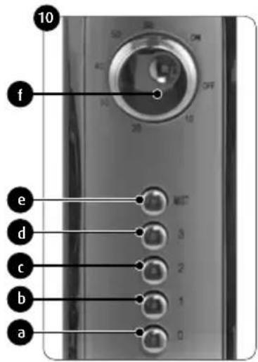
f. first fan speed switch "3"
g. humidifier switch
- Fan pipes
- Fan base
- Locking screws (knurled)
- Power cable
- Mist atomiser
- Tank lid
- Water tank with capacity of 3.2 litres
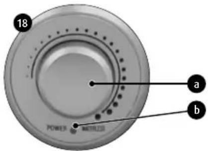
- Humidifier panel
a. fog intensity control knob
b. water status lamp
- Humidifier housing
On top of the functions characteristic for this type of device, the fan is equipped in an ultrasound air humidifier which atomises water into 1-5 micrometre particles. The atomised water goes to the sprayer assembled in the fan dish, which significantly accelerates the process of humidification.
BEFORE FIRST USE
- Unpack all fan components from the cardboard box. Identify all parts, remove any bags, stickers and fillers.
- Inspect the device carefully for damage which may have occurred in transport. In case of doubts or suspected damage, contact the seller.
- Assemble the device thoroughly following the instructions included in the "DEVICE ASSEMBLY" chapter.
- Make sure that the data on the device rating plate match your power mains system.
DEVICE ASSEMBLY
- Place the plastic base (12) on a ballast similar in shape to the base.
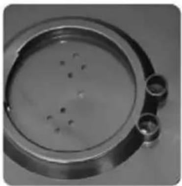
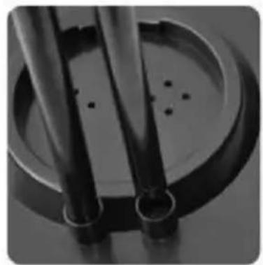
- Remove the screws from the pipe ends (11). Place the pipe ends into their sockets in the base. Put on the washers and screw the tubes with the screws from the bottom side of the base (fig.1).
natural_image
Close-up of a metallic circular container with small dark spots, possibly a petri dish or sample (no visible text or symbols)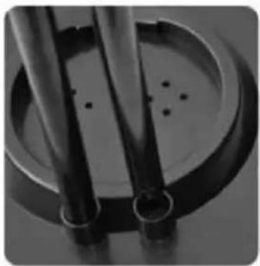
natural_image
Close-up of two metallic cylindrical components with circular bases and small holes, no visible text or symbols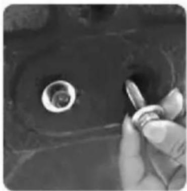
natural_image
Close-up of a hand holding a small object near a circular hole (no visible text or symbols)fig. 1
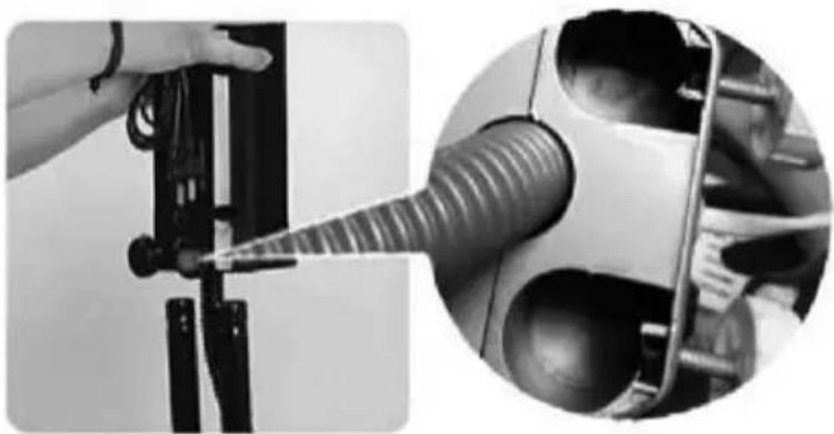
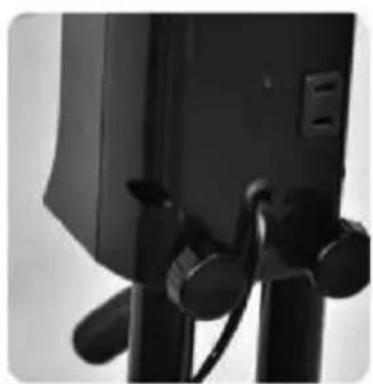
- Loosen the two knurled screws (13) at the back of the fan control panel (do not loosen the screws completely as they may fall out). Locate the two holes for the pipe ends (11) in the housing. Replace the casing, press down and tighten the thumb screws (fig.2)
natural_image
Close-up of a hand using a tool to lift a car component, with a close-up inset showing the same lever (no text or symbols visible)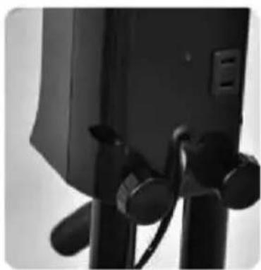
natural_image
Close-up of a black camera module with attached sensors and cables (no visible text or symbols)fig. 2
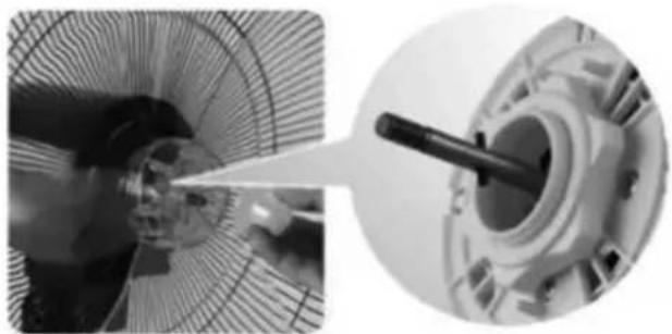
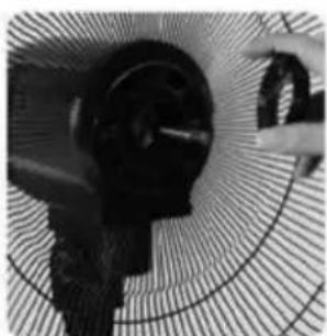
- Place the rear propeller cover (6) on the motor casing (7), making sure that the wire handle on the back of the cover is up, and screw the cover on with the nut (5). Place the propeller (3) on the motor shaft and screw it on with the nut (2) counterclockwise (fig.3).
natural_image
Close-up of a mechanical component with a circular mesh pattern and a hand adjusting it (no visible text or symbols)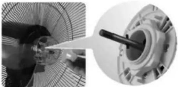
natural_image
Close-up of a mechanical component with a pointed tool inserted, shown in two circular views (no visible text or symbols)
natural_image
Close-up of a person using a tool to clean or inspect a circular fan (no visible text or symbols)fig. 3
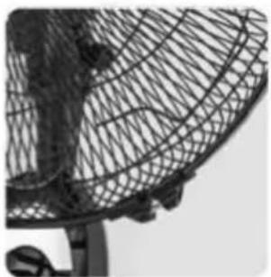
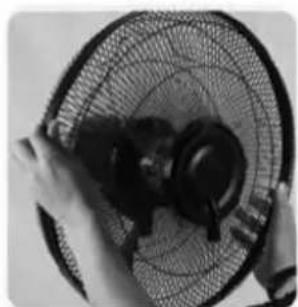
- Place the front propeller cover (1) so that the mist atomiser nozzle (15) is facing downwards, put the ring (4) on the perimeter of the covers so that the covers fit tightly together and tighten the screw in the ring to lock the covers (fig.4)
natural_image
Close-up of a person holding a fan blade with mesh grille (no visible text or symbols)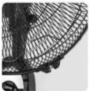
natural_image
Close-up of a wire mesh fan or antenna structure (no text or symbols visible)Fig. 4
CAUTION! Do not start the fan without correctly assembled propeller covers.
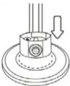
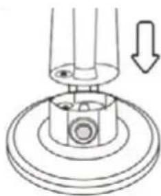
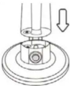
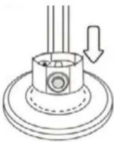
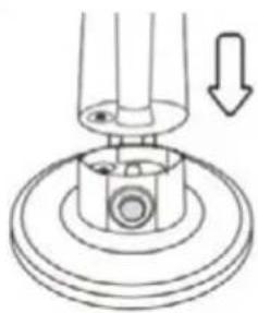
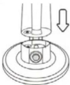
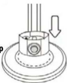
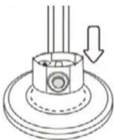
- Place the humidifier casing (19) in the base recess (12). The casing fits into the recess in one correct position (fig.5).
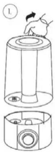
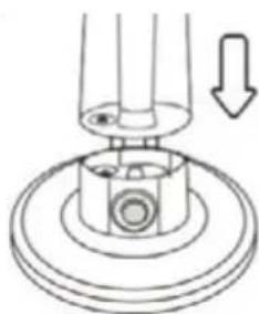
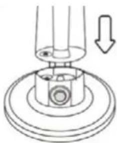
- Place the water tank (17) on the humidifier casing (19). The tank fits into the casing in one correct position (fig.6). Place the tank cover (16) on the water tank.
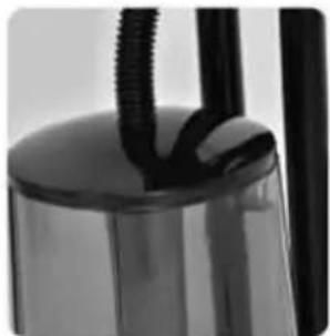
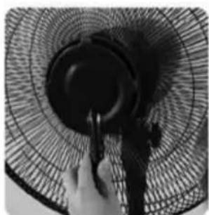
- Connect the corrugated fog hose (9) to the water tank lid on one side and to the mist atomiser nozzle port on the other side (fig.7).
natural_image
Close-up of a hand holding a black fan blade, no visible text or symbols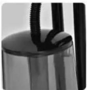
natural_image
Close-up of a glass container with black straws, no visible text or symbolsFig. 7
natural_image
Technical diagram of a mechanical component with a downward arrow indicating motion (no text or symbols)Fig. 5
natural_image
Mechanical assembly diagram showing a rotating component with a downward arrow indicating motion (no text or symbols)Fig. 6
FILLING THE WATER TANK
CAUTION! Always switch off the device and disconnect it from mains before filling the water tank.
CAUTION! When filling the water tank and in the course of regular operation the fan should be placed on a hard, dry, smooth, horizontal and stable surface.
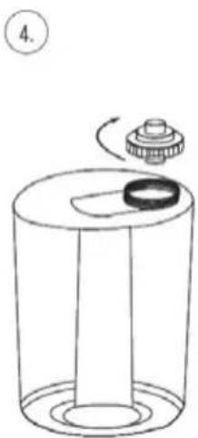
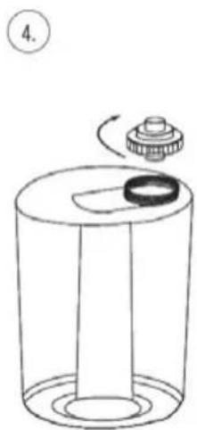
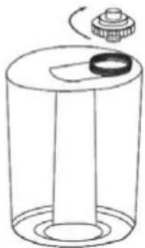
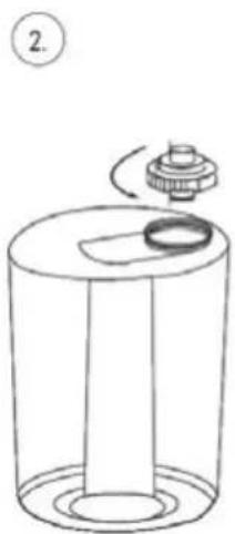
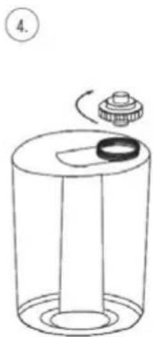
- Remove the water tank from the machine using the handle on the tank
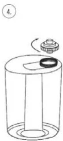
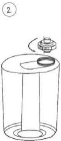
- Turn the container 180° and unscrew the water filler cap
- Pour cool, clean water, preferably distilled and filtered, into the tank. Be careful not to overfill the tank.
- Fit and screw on the water stopper.
- Turn the water tank 180^ again and place it on the humidifier casing (19).
CAUTION!!!
- the water being poured in must not be hotter than 40°C
- do not add any chemicals or odours to the water
- do not pour water directly into the humidifier (19) – the valve in the water cap will automatically dispense the desired amount of water into the humidifier
natural_image
Simple line drawing of a cylindrical container with a side panel and a rotating knob, no text or symbols present.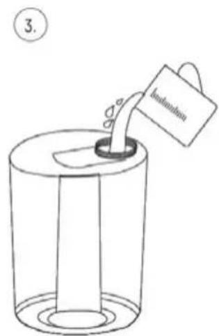
natural_image
Simple line drawing of a cylindrical container with a side knob and a small mechanical component, no text or symbols present.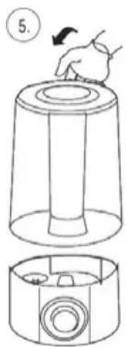
Filling the water tank
DEVICE OPERATION
CAUTION! The device can be switched on only after its complete assembly. Activation of a partially assembled device does not ensure safe and proper operation.
- Place the unit on hard, dry, level, horizontal and stable surface. If you will be using the humidification function then fill the water tank with water.
- Connect the device to the mains supply and set the time clock knob (10f) to the "ON" position.
- Use the buttons (10 b,c,d) to set the desired airflow speed:
- "1" - low speed
- "2" - medium speed
- "3" - high speed
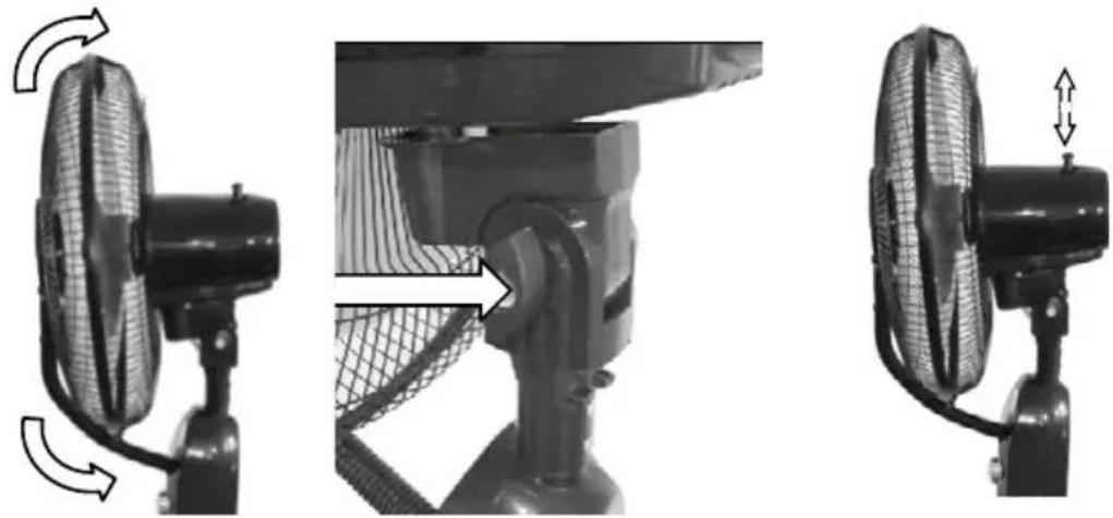
- The angle of airflow can be changed by loosening the nut (8). When the angle of the fan head is correctly set, screw the nut (8) back on.
natural_image
Three-panel diagram showing a fan assembly process: top-down, side-up, and top-down with directional arrows indicating motion (no text or symbols)Changing the blowing angle Fan oscillation on/off
- The fan oscillation can be switched on/off using the button on the motor casing by pressing it in or pulling it slightly upwards.
- The humidifier function is activated by pressing the "MIST" button (10e). Operation of the humidifier will be signalled by the status lamp (18b) lighting up green. Water mist will be visible in the mist atomiser (15).
- With the knob (18a) you can adjust the intensity of the water mist ejection
- The lack of water will be signalled by the status lamp (18b) which will turn red. The device must then be switched off, disconnected from the mains supply and the water in the tank (17) must be refilled.
- The fan and humidifier functions are independent of each other, i.e. you can set the operation of only the fan or only the humidifier or both functions at the same time.
- The timer knob allows you to set the operating time after which the unit will automatically switch off. Time available ranges between 0-60 minutes. The "ON" position starts the device without a time limit.
- The device is switched off by pressing the "0" button (10a) and turning the clock knob to the "OFF" position
CLEANING AND MAINTENANCE
CAUTION! Unplug the appliance from the mains before cleaning and maintenance.
CAUTION! Do not submerge the appliance in water or other liquids!
- Clean the casing and propeller with a damp cloth and then wipe it dry. Use a bit of a gentle detergent to remove persistent grime. The propeller can be accessed by removing the front casing.
- You can gently dust the mesh casing of the propeller with a soft brush. For a better cleaning effect, you can remove the casings before cleaning.
- Clean the internal water container located where the main water tank is mounted (upper part of the humidifier casing "18") of any remaining water by tilting it over a vessel. Then clean the inside with a damp cloth. Pay special attention to the cleanliness of the float and
the ultrasonic generator and at the same time take special care when cleaning these components. Clean the internal water container at least once a week.
4. Water tank cleaning (17):
- pour about 0.5 l of water with detergent into the tank and screw the plug
- shake the tank several times
- pour out water, rinse the tank with clean water
- wash the outer surfaces of the tank with lukewarm water with detergent, rinse and dry
- when cleaning the plug pay special attention to the cleanliness of the gasket under the thread and in the valve. If necessary, you can additionally clean them using a brush with delicate bristle
- clean the tank once every week
- Only regular cleaning of the appliance will prevent the build-up of limescale and the development of fungi and bacteria. If the break in operation will be longer than 2 days then absolutely remove all water from the device. Do not use aggressive detergents or abrasive cleaning agents for cleaning.
PROBLEMS AND TROUBLESHOOTING
| PROBLEM CAUSE SOLUTION | |
| The humidifier does not spray mist a. contaminated waterb. water tank crackedc. water tank empty | a. clean the tank and pour clean waterb. pour out water and check for cracksc. add water to the tank |
| Humidifier does not start a. the float does not rise upb. water tank empty | a. move the float slightly within the internal water tankb. add water to the tank |
| Fan and humidifier do not start a. no power, device disconnected from mains | a. check the power supply, connect the device to mains |
| Fan does not work normally a. plug or cable damagedb. propeller damaged or blocked | a. contact an authorised service centreb. replace the propeller, eliminate the cause of blocking |
Technical data sheet
MPM AGD S.A.
MODEL: MWP-20
Description Symbol Value Unit
| Maximum flow rate of the fan F 59,3 m | ^3/min | ||
| Fan power P 52,1 W | |||
| Operating value SV 1,1 (m | ^3/min)/W | ||
| Power consumption in standby mode P | SB | 0 | W |
| Fan's sound power level L | WA | 57 dB(A) | |
| Maximum air speed | C | 3,1 | m/s |
| Seasonal electricity consumption | Q | 16,7 | kWh/a |
| Standards used for measuring the operational values | IEC 60879:2019 |
To get additional information, contact MPM AGD S.A.
ul. Brzozowa 3
Milanówek 05-822, Polska
tel. (22) 380-52-00
BDO: 000027599
TECHNICAL SPECIFICATIONS
See the product's nameplate for technical specifications.
Length of the power cord: 1.70 m
Noise: L_WA = 57 dB

CAUTION! MPM agd S.A. may change the technical features of the product without notice.
PROPER DISPOSAL OF THE PRODUCT (waste electrical and electronic equipment)
Marking on the product indicates that after the service–life of the product expires, it should not be disposed with other type of municipal waste. Used equipment may have a negative impact on the environment and health of people due to potentially containing hazardous substances, mixtures and components. Mixing electric waste with other types of waste or disassembling those in an unprofessional manner may cause a release of substances that are hazardous to the environment and health. Used equipment should be handed-over to a point for collection of electric waste. In order to obtain detailed information regarding the electric waste collection points, the user should contact the municipal point of electric waste collection or used equipment processing department.
WSKAZÓWKI DOTYCZĄCE BEZPIECZEŃSTWA UŻYTKOWANIA
natural_image
Close-up of a metallic circular component with internal markings and two small protrusions (no visible text or symbols)rys. 1
natural_image
Close-up of two metallic pipes with circular bases and small dots on the surface (no text or symbols visible)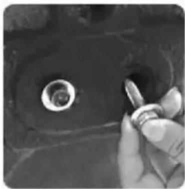
natural_image
Close-up of a hand holding a small metallic object with a circular hole, no visible text or symbolsnatural_image
Close-up of a hand using a tool to lift a car component, with a magnified inset showing the internal structure (no text or symbols visible)rys. 2
natural_image
Close-up of a black camera module with tripod base and adjustment knobs (no visible text or symbols)natural_image
Two views of a person's fan with mesh grille, showing front and side views (no text or symbols visible)rys. 4
natural_image
Close-up of a hand holding a black fan blade with a handle, no visible text or symbols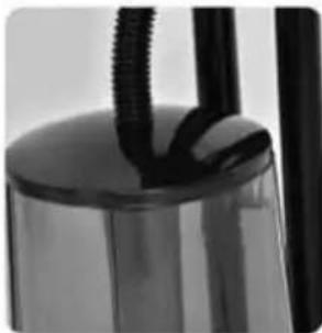
natural_image
Close-up of a metallic cylindrical object with black ribbeds and a cylindrical base (no visible text or symbols)rys. 7

natural_image
Diagram of a mechanical component with a downward arrow indicating force or direction (no text or symbols present)rys. 5
natural_image
Diagram of a mechanical assembly with a rotating component and a downward arrow indicating motion (no text or symbols)rys. 6
NAPEŁNIANIE ZBIORNIKA NA WODE
natural_image
Simple line drawing of a cylindrical container with a lid and a curved top, no text or symbols present.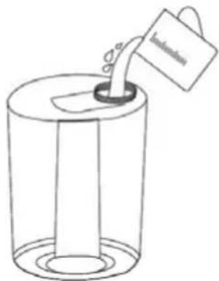
4.
natural_image
Simple line drawing of a cylindrical container with a side cover and a small knob, no text or symbols present.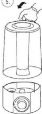
PROBLEMY I SPOSÓB I ICH USUWANIA
natural_image
Close-up of a petri dish with visible colonies, no text or symbols present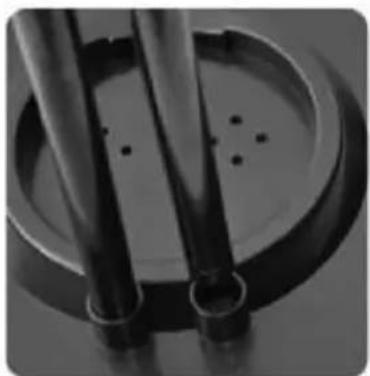
natural_image
Close-up of two metallic cylindrical components with circular base and small holes, no visible text or symbols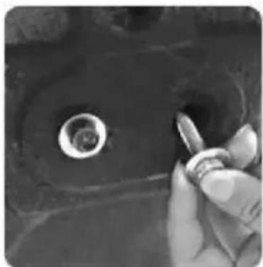
natural_image
Close-up of a hand holding a small metallic object with a circular hole, no visible text or symbolsрис. 1
natural_image
Close-up of a hand using a tool to lift a car component, with a close-up inset showing the cable being inserted into a car (no text or symbols visible)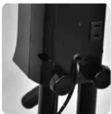
natural_image
Close-up of a black camera module with tripod base and adjustment knobs (no visible text or symbols)рис. 2
natural_image
Close-up of a person holding a mesh fan with black plastic components (no visible text or symbols)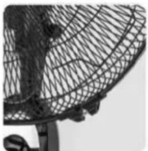
natural_image
Close-up of a wire mesh fan with visible blades and mounting feet (no text or symbols)рис. 4
natural_image
Close-up of a hand holding a black fan blade with a handle, showing internal blades and mesh pattern (no text or symbols visible)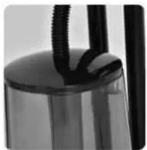
natural_image
Close-up of a glass container with black cylindrical objects and a coiled string (no visible text or symbols)рис. 7
natural_image
Diagram of a mechanical component with a downward arrow indicating motion or force (no text or symbols present)рис. 5
natural_image
Technical diagram of a mechanical assembly with a rotating component and a downward arrow indicating motion (no text or symbols)рис. 6
flowchart
graph TD
    A["Step 1: Linger with mouse"] --> B["Step 2: Stopping a button"]
    B --> C["Step 3: Stopping a bag with a handle"]
    C --> D["Step 4: Stopping a valve with a knob"]
    D --> E["Step 5: Stopping a hand holding a tool"]
- Predný kryt vrtule
- Matica vrtule
- Vrtula
- Prstenec na kryty
- Matica zadného krytu vrtule
- Zadný kryt vrtule
- Telo ventilátora
- Skrutka na nastavenie smeru prúdenia vzduchu
- Rebrovaná trubica na hmlu
- Ovládací panel
natural_image
Close-up of a metallic circular object with small dark spots, possibly a petri dish or sample (no visible text or symbols)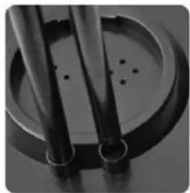
natural_image
Close-up of two cylindrical metal pipes with circular bases, no visible text or symbols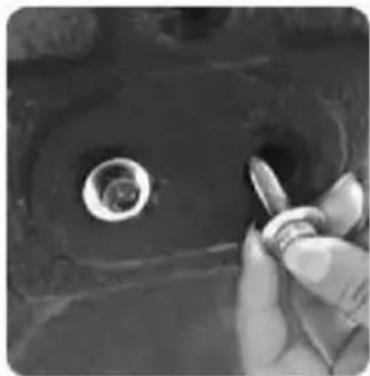
natural_image
Close-up of a hand holding a small object near a circular hole (no visible text or symbols)obr. 1
natural_image
Close-up of a hand using a tool to lift a car component, with a magnified inset showing the internal structure (no text or symbols visible)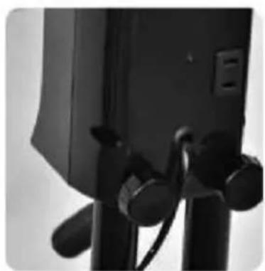
natural_image
Close-up of a black camera module with attached cables and a small outlet (no visible text or symbols)obr. 2
natural_image
Two views of a metal fan with mesh blades, one showing the blade and the other the blade (no text or symbols visible)obr. 4
natural_image
Two black-and-white photos showing a fan blade and a close-up of its glass container with coiled tubing (no text or symbols visible)obr. 7
natural_image
Technical diagram of a mechanical component with a downward arrow indicating motion (no text or symbols)obr. 5
natural_image
Mechanical assembly diagram showing a rotating component with a downward arrow indicating motion (no text or symbols)obr. 6
NAPLÍNANIE NÁDOBY NA VODU
natural_image
Simple line drawing of a cylindrical container with a rotating knob and a small inset showing the lid (no text or symbols)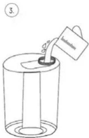
natural_image
Simple line drawing of a cylindrical container with a side knob and a small mechanical component, no text or symbols present.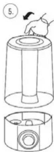
NAPLŇANIE NÁDOBY NA VODU
POUŽÍVANIE ZARIADENIA
We wish you satisfaction from using the product and invite you to check a wide range of other MPM appliances
- WENTYLATOR Z FUNKCJĄ NAWILŻANIA MWP-20
- NAPLNĚNÍ NÁDRŽKY NA VODU
- POUŽITÍ ZAŘÍZENÍ
- FÜLLEN DES WASSERBEHÄLTERS
- INSTRUCTIONS ASSOCIATED WITH USE SAFETY
- BEFORE FIRST USE
- DEVICE ASSEMBLY
- CAUTION! Do not start the fan without correctly assembled propeller covers.
- FILLING THE WATER TANK
- CAUTION!!!
- DEVICE OPERATION
- CLEANING AND MAINTENANCE
- Water tank cleaning (17):
- Technical data sheet
- TECHNICAL SPECIFICATIONS
- PROPER DISPOSAL OF THE PRODUCT (waste electrical and electronic equipment)
- WSKAZÓWKI DOTYCZĄCE BEZPIECZEŃSTWA UŻYTKOWANIA
- NAPEŁNIANIE ZBIORNIKA NA WODE
- NAPLÍNANIE NÁDOBY NA VODU
- POUŽÍVANIE ZARIADENIA
Brand : MPM
Model : MWP-20
Category : Fan