
TEG5O - Chauffe-eau instantané et chauffe-eau GORENJE - Free user manual and instructions
Find the device manual for free TEG5O GORENJE in PDF.

| Product Type | Instantaneous Water Heater (Tankless) |
| Brand | Gorenje |
| Model | TEG5O |
| Dimensions (H x W x D) | 300 mm x 200 mm x 150 mm |
| Weight | 2.5 kg |
| Power Supply | 220-240 V ~ 50 Hz |
| Rated Power | 3.5 kW |
| Water Flow Rate | 3-5 L/min |
| Temperature Range | 30-60 °C |
| Main Functions | Instant heating, adjustable temperature, thermal protection, dry-heat protection |
| Display | LED temperature display |
| Controls | Touch panel or rotary knob |
| Installation | Wall-mounted, horizontal or vertical |
| Water Connection | G 1/2 inch inlet and outlet |
| Electrical Protection Class | IP24 |
| Safety Features | Overheat protection, flow sensor, pressure relief valve |
| Maintenance | Periodic descaling, check for leaks |
| Cleaning | Wipe with damp cloth, avoid abrasives |
| Spare Parts | Heating element, thermostat, flow sensor, PCB |
| Repairability Index | 7.5/10 |
| Warranty | 2 years |
| Country of Origin | Slovenia |
| Certifications | CE, RoHS |
Frequently Asked Questions - TEG5O GORENJE
User questions about TEG5O GORENJE
0 question about this device. Answer the ones you know or ask your own.
Ask a new question about this device
Download the instructions for your Chauffe-eau instantané et chauffe-eau in PDF format for free! Find your manual TEG5O - GORENJE and take your electronic device back in hand. On this page are published all the documents necessary for the use of your device. TEG5O by GORENJE.
USER MANUAL TEG5O GORENJE
natural_image
White rectangular water heater with control knob and two blue/red ports at the bottom (no visible text or symbols)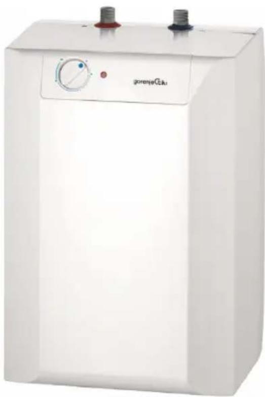
natural_image
White industrial water heater unit with control knob and two side gauges (no visible text or symbols on body)TEG 5 - 10

Instructions for Use 10

natural_image
Diagram of a faucet with a valve and drain, no text or symbols present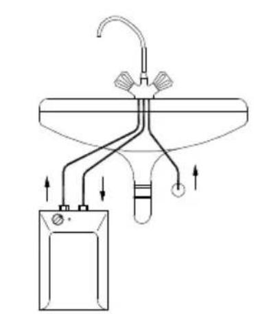
natural_image
Diagram of a laboratory apparatus with tubing and a container, no visible text or symbolsThe appliance may be used by children older than 8 years old, elderly persons and persons with physical, sensory or mental disabilities or lacking experience and knowledge, if they are under supervision or taught about safe use of the appliance and if they are aware of the potential dangers.
Children should not play with the appliance.
Children should not clean or perform maintenance on the appliance without supervision.
⚠️ Installation should be carried out in accordance with the valid regulations and according to the instructions of the manufacturer and by qualified staff.
The water heater is constructed for cross-flow (non-pressure) system of installation!
Before connecting it to the power supply, the water heater must be filled with water!
If the heater is to be disconnected from the power supply, please drain any water from the heater to prevent freezing.
⚠️ Please do not try to fix any defects of the water heater on your own. Call the nearest authorised service provider.
Our products incorporate components that are both environmentally safe and harmless to health, so they can be disassembled as easily as possible and recycled once they reach their final life stage.
Recycling of materials reduces the quantity of waste and the need for production of raw materials (e.g. metals) which requires a substantial
amount of energy and causes release of harmful substances. Recycling procedures reduce the consumption of natural resources, as the waste parts made of plastic and metal can be returned to various production processes.
For more information on waste disposal, please visit your waste collection centre or the store where the product was purchased.
Dear buyer, thank you for purchasing our product. Prior to the installation and first use of the electric water heater, please read these instructions carefully.

This water heater has been manufactured in compliance with the relevant standards and tested by the relevant authorities as indicated by the Safety Certificate and the Electromagnetic Compatibility Certificate. The technical characteristics of the product are listed on the label affixed between the inlet and outlet pipes. The installation must be carried out by qualified staff. All repairs and maintenance work within the water heater, e.g. lime removal, must be carried out by an authorised maintenance service provider.
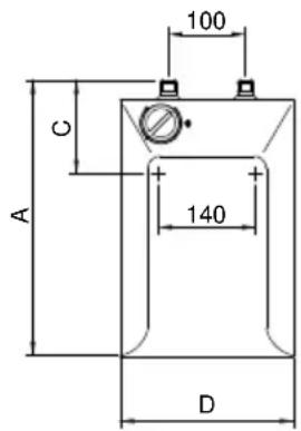
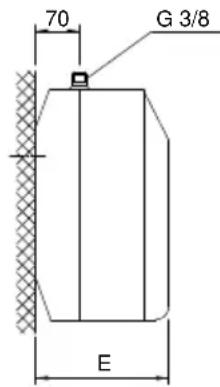
INSTALLATION
The water heater shall be built in according to the drawing and table with dimensions in a premise where there is no frost, as close as possible to the water outlets. It has to be fitted to the wall using appropriate wall screws with a minimum diameter of 5 mm.
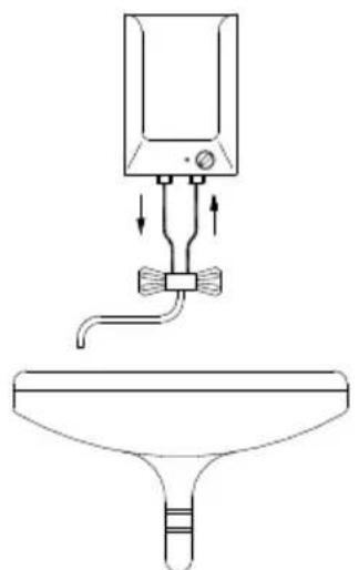
With regard to the needs, you can chose execution above the sink (TEG 0520 O/A; TEG 1020 O/A) or an execution under the sink (TEG 0520 U/A; TEG 1020 U/A).
| A | B | C | D | E | |
| TEG 0520 O/A | 390 | 264 | 256 | 213 | |
| TEG 0520 U/A | 390 | 138 | 256 | 213 | |
| TEG 1020 O/A | 471 | 371 | 310 | 265 | |
| TEG 1020 U/A | 471 | 196 | 310 | 265 |
Connection and installation dimensions of the water heater [mm
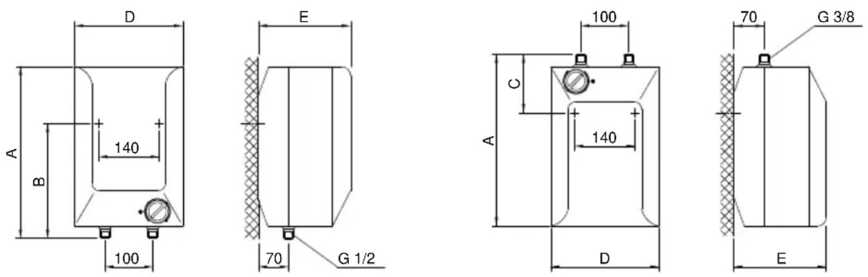
Execution above the sink
Execution under the sink
CONNECTION TO THE WATER SUPPLY
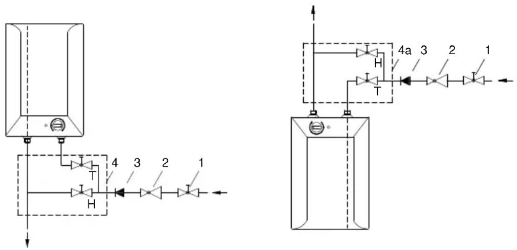
The water heater is constructed for cross-flow (non-pressure) system of installation. This system enables supply of water only at one outlet point. The connection must be performed correspondingly to the diagram of the water supply.
For cross-flow system of installation an adequate mixing tap must be purchased. For the execution above sink is needed a mixing tap above sink, and for execution under the sink the mixing tap under the sink. Inlet of cold water is marked with blue colour and the outlet of hot water is marked with red colour. Upon the inlet pipe before the mixing tap it is mandatory to built-in a non-return valve preventing the running of water of the tank if the water in the network runs short. If the pressure in water supply network surpasses 5 bar, before the mixing tap also a reduction valve must be built in.
By choice of the cross-flow mixing tap, particular attention must be paid to the data of supplier about reduction of pressure by the resistance appearing by flow of water through the mixing tap. By entirely open outlet valve this must not surpass 0,2 bar. To the outlet pipe of mixing tap no device driven by water or spray nozzle may be connected, which could cause the increase of pressure in the tank of the water heater. If these instructions shall not be respected during the operation, a damage of the heater may occur.
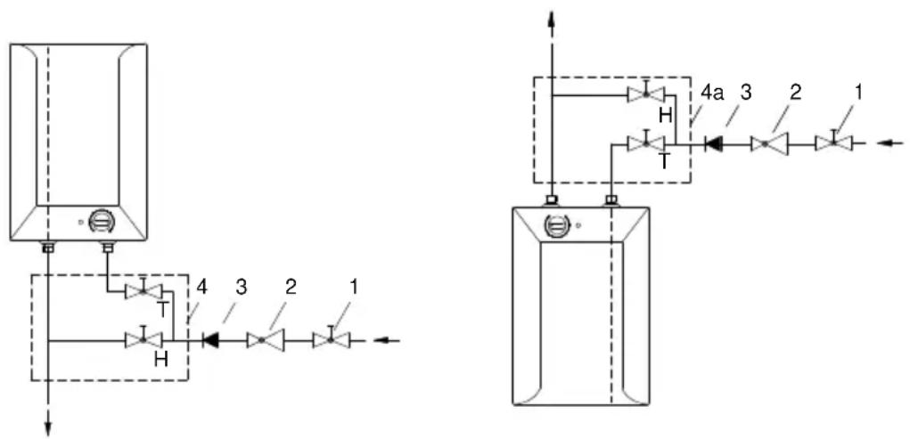
Execution above the sink
Execution under the sink
Legend:
1 - Closing valve
2 - Pressure reduction valve
3 - Non-return valve
4 - Cross-flow mixing tap - above sink
4a - Cross-flow mixing tap - under sink
H - Cold water
T - Hot water

natural_image
Diagram of a faucet with a valve and drain, no text or symbols present
natural_image
Pure diagram of a laboratory apparatus with tubing and a container, no text or symbols presentPrior to the electric connection, the heater must be obligatorily filled with water. By first filling the faucet for the hot water upon the mixing tap must be opened. The heater is filled with water when the water starts to run through the outlet pipe of the mixing tap. If the heater at connection would not be filled with water, at first switching-on the damage of thermal fuse shall occur and the heater shall not operate at all.
CONNECTING THE WATER HEATER TO THE POWER SUPPLY NETWORK
Connection of the water heater to the electric network must be performed according to standards for electric installation. The heater shall be connected to electric power supply over electric cable with plug. If the built-in cable shall be replaced with a new longer, the built-in cable may be removed and the new connecting cable inserted where the cable wires shall be screwed to the connection terminal. In order to do this the plastic lining of the water heater must be removed. This is done so that at first the plate is removed, inserted in the front side of the plastic lining. The plate is released so that in the slot between the inserted plate and the plastic lining at first at the thermostat knob and on the side in front of the knob cautiously a screwdriver is pushed in. When the plate is released at both sides, it can then be removed by hand. Than the thermostat knob is removed and the screw under the knob is unscrewed. At last also all four screws for fixing of plastic lining are unscrewed and the lining removed.
Legend:
1 - Thermostat
2 - Thermal cut-off
3 - Electric heating element
4 - Pilot lamp
5 - Connection terminal
L - Live conductor
N - Neutral conductor
± - Earthing conductor
Electric installation
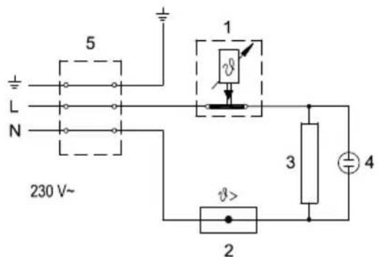
CAUTION: Before any intervention into the interior of the water heater, disconnect it from the power supply network! This intervention may only be performed by a trained professional!
After connecting to the water and power supply, the heater is ready for use. By turning the knob of thermostat at the front side of the protecting cover, the wished temperature of water 75 °C is chosen. We recommend the adjustment of the knob to the position "e". Such an adjustment is the most economic, with it the temperature of water shall be approximately 41 °C in case of TEG 0520 or 35 °C in case of TEG 1020, the excretion of lime-stone and thermal loss shall be smaller as by adjustment to higher temperature (poz. II - 55 °C in III - 75 °C).
The operation of electric immersion heaters is shown by pilot light which is lit during the time until the water in the heater is heating to the chosen temperature or to the intended switch off. During the heating the volume of water in the heater is increasing, which causes the dropping of water from the mixing valve. By strong squeezing of the mixing valve the dropping can not be stopped but the mixing valve can be damaged.
When the heater shall not be used during a longer time, its contents must be protected against freezing so that the electricity shall not be switched off, but the thermostat knob shall be adjusted to the position " * With this adjustment the heater shall maintain the water temperature by approximately 9 °C. But when the heater is switched-off the electric network, at risk for freezing, the water must be emptied from it. Water from the heater is drained through the inlet/outlet pipe of the heater.
The outside of the heater is cleaned by mild solution of detergent. The solvents or rough cleaning means should not be used. By regular service check impeccable operation shall be assured and a long lifetime of the heater. The first check must be performed by authorised service workshop after approximately two years after the first connection. At check, it necessary lime stone must be cleaned which with regard to the quality, quality and temperature of the water used is gathered in the inside of the water heater. Service workshop shall after check recommend also the date of next check.
Never try to repair any possible faults of the heater by yourself, but inform about it the nearest authorised service workshop.
TECHNICAL PROPERTIES OF THE APPLIANCE
| Type | TEG 0520 O/A | TEG 0520 U/A | TEG 1020 O/A | TEG 1020 U/A | |
| Declared load profile | XXS | XXS | XXS | XXS | |
| Energy efficiency class 1) | A | A | A | A | |
| Water heating energy efficiency (ηwh) 1) | [%] | 35,2 | 35 | 35,3 | 35,1 |
| Annual electricity consumption 1) | [kWh] | 525 | 527 | 523 | 525 |
| Daily electricity consumption 2) | [kWh] | 2,475 | 2,49 | 2,464 | 2,477 |
| Thermostat temperature settings | e* | ||||
| Value of "smart" | 0 | 0 | 0 | 0 | |
| Volume | [l] | 5,5 | 5,7 | 9,8 | 9,9 |
| Weight / Filled with water | [kg] | 3,5 / 8,5 | 4 / 14 | ||
| Power of electrical heater | [W] | 2000 | |||
| Voltage | [V~] | 230 | |||
| Protection class | I | ||||
| Degree of protection | IP24 | ||||
| Heating time from 10 °C to 65 °C | [min] | 10 | 20 | ||
| Packaging dimensions | [mm] | 215x265x425 | 275x320x500 | ||
* The "e" position of the regulation knob corresponds to a water temperature of approx. 41 °C by TEG 0520 and 35 °C by TEG 1020
1) EU Regulation 812/2013; EN 50440
2) EN 50440
WE RESERVE THE RIGHT TO MAKE CHANGES THAT DO NOT IMPAIR THE FUNCTIONALITY OF THE DEVICE.
The user manual can also be found at our website http://www.gorenje.com.
HINWEISE
natural_image
Diagram of a faucet with a drain and outlet, showing fluid flow direction (no text or labels)
natural_image
Pure diagram of a laboratory apparatus with tubing and control panel (no text or symbols)Inačica ispod umivaonika
PRIKLJUČIVANJE NA VODOVODNU MREŽU
natural_image
Diagram of a faucet with a valve and drain, no text or symbols present
natural_image
Pure diagram of a laboratory apparatus with tubing and a container, no text or symbols presentModel pod umivaonikom
PRIKLJUČIVANJE NA VODOVOD
Bojler je građen za protočni (bez pritiska) sistem priključenja. Ovaj sistem omogućava potrošnju vode samo na jednom potrošnom mestu. Priključenje je potrebno izvesti u skladu sa shemom vodovodnog priključka.
Za protočni sistem priključivanja morate da ugradite odgovarajuću bateriju za mešanje. Za izvođenje nad umivaonikom, potrebni su vam protočna baterija za iznad umivaonika, a za izvođenje pod umivaonikom protočna baterija za ispod umivaonika. Dovod i odvod vode su na cevima bojlera označeni bojama. Dovod hladne vode označen je plavom bojom, a odvod tople vode crvenom. Na dovodnu cev ispred baterije za mešanje potrebno je obavezno ugraditi nepovratni ventil koji sprečava isticanje vode iz kotla ako u mreži nema vode. Ako pritisak u vodovodnoj mreži premašuje 5 bara, ispred baterije za mešanje morate ugraditi i redukcioni ventil. Kod izbora protočne baterije za mešanje posebnu pažnju namenite podatku proizvođača o padovima pritiska zbog otpora koji nastupaju kod protoka vode kroz bateriju za mešanje. Kod potpuno otvorenog istočnog ventila, on ne sme da premašuje 0,2 bara. Na izlivnu cev baterije za mešanje takođe ne smete priključiti nijednu spravu na vodeni pogon ili vodeni raspršivač koji bi mogao da uzrokuje povećanje pritiska u kotlu grejača. Ako se ne budete držali ovih uputstava, tokom rada može doći do oštećenja bojlera.
Varijanta iznad umivaonika
Varijanta ispod umivaonika
Legenda:
1 - Ventil za zatvaranje
2 - Ventil za redukciju pritiska
3 - Nepovratni ventil
4 - Protočna baterija za mešanje - iznad umivaonika
4a - Protočna baterija za mešanje - ispod umivaonika
H - Hladna voda
T - Topla voda
natural_image
Diagram of a faucet with a valve and drain, no text or symbols present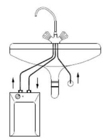
natural_image
Pure diagram of a laboratory apparatus with tubing and a container, no text or symbols presentPre električnog priključivanja, bojler treba obavezno prvo napuniti vodom! Prilikom prvog punjenja, otvorite slavinu za toplu vodu. Bojler je pun kad iz slavine počne da teče voda kroz izlivnu cev baterije za mešanje. Ako bojler kod priključivanja ne napunite vodom, kod prvog uključenja doći će do oštećenja toplotnog osigurača i bojler uopšte neće raditi.
PRIKLJUČIVANJE NA ELEKTRIČNU MREŽU
Priključivanje bojlera na električnu mrežu mora da se odvija u skladu sa standardima za električne instalacije. U električnoj instalaciji mora da bude ugrađena prirema za odvajanje svih polova. Bojler priključite na električnu mrežu preko priključnog kabla. Ako želite ugrađeni kabl da zamenite novim, dužim, možete ugrađeni kabl da odstranite, a novi da pričvrstite u uvodnicu kabla i žice kabla da privijete u priključnu sponu. Da biste to mogli da uradite, prvo morate da skinete plastičnu oplatu bojlera. To ćete uraditi tako da prvo odstranite pločicu (važi za modele sa umetnutnom pločicom) koja je umetnuta u prednju stranu plastične oplate. Pločicu oslobodite na taj način što u prorez između pločice za umetanje i plastične oplate prvo uz dugme termostata, a zatim i na strani nasuprot dugmeta oprezno gurnete izvijač. Kada pločicu oslobodite na obe strane, možete je odstraniti rukom. Zatim odstranite dugme termostata i odvijte šraf za pričvršćivanje ispod dugmeta. Na kraju odšrafite i sve šrafove za pričvršćivanje plastične oplate i oplatu odstranite.
1 - Termostat
2 - Toplotni osigurač
3 - Grejač
4 - Kontrolna svetiljka
5 - Priključne kleme
L - Faza
N - Nula
± - Uzemljenje

Šema povezivanja električnih provodnika
UPOZORENJE: Pre svake intervencije u unutrašnjosti bojlera, obavezno isključite bojler iz električne mreže! Intervenciju može obaviti samo osposobljeni stručnjak!
UPOTREBA I ODRŽAVANJE
Posle priključivanja na vodovodnu i električnu mrežu bojler je spreman za upotrebu. Okretanjem dugmeta na termostatu koji je na prednjoj strani zaštitnog poklopca, birate željenu temperaturu vode do 75 °C. Preporučujemo podešavanje dugmeta na položaj "e". Takvo podešavanje je najštedljivije; kod njega će biti temperatura vode približno 41 °C kod TEG 0520 odn. približno 35 °C kod TEG 1020, odvajanje vodenog kamenca i toplotni gubitak će biti manji nego kod podešavanja na višu temperaturu (poz. II - 55 °C i III - 75 °C). Delovanje električnog grejača pokazuje kontrolna svetiljka koja svetli sve dok se voda u bojleru ne zagreje do odabrane temperature ili do namenskog isključivanja. U bojleru se zbog zagrevanja zapremina vode povećava, a to uzrokuje kapanje iz cevi baterije za mešanje. Jakim zatezanje ručice na bateriji za mešanje ne možete sprečiti kapanje vode, već možete bateriju da pokvarite.
Ako nemate nameru da koristite bojler duže vremena, zaštitite njegov sadržaj od smrzavanja tako da ne isključujete električnu energiju, a dugme termostata podesite na položaj "*. Na tom podešavanju će bojler održavati temperaturu vode na približno 9 °C. Ukoliko isključite bojler iz električne mreže, morate da ispustite vodu iz njega zbog opasnosti od smrzavanja vode. Voda iz bojlera se prazni kroz dovodnu/ odvodnu cev bojlera.
Spoljašnjost bojlera čistite blagim tečnim sredstvima za čišćenje. Nemojte koristiti razređivače i gruba sredstva za čišćenje.
Redovnim servisnim pregledima obezbedićete besprekorno delovanje i dug životni vek bojlera. Prvi pregled neka ovlašćena servisna služba obavi približno dve godine posle priključenja. Prilikom pregleda se po potrebi čisti vodeni kamenac, koji se s obzirom na kvalitet, količinu i temperaturu potrošene vode sakuplja u unutrašnjosti bojlera. Servisna služba će vam posle pregleda bojlera, s obzirom na utvrđeno stanje, preporučiti i datum sledeće kontrole.
Molimo da eventualne kvarove ne popravljate sami nego da o njima obavestite najbližu servisnu službu.
TEHNIČKE KARAKTERISTIKE BOJLERA
| Tip | TEG 0520 O/A | TEG 0520 U/A | TEG 1020 O/A | TEG 1020 U/A | |
| Određeni profil opterećenja | XXS | XXS | XXS | XXS | |
| Razred energetske efikasnosti ^1) A | A A A | ||||
| Energetsta efikasnost pri zagrevanju vode (ŋwh) ^1) | [%] | 35,2 | 35 | 35,3 | 35,1 |
| Godišnja potrošnja električne energije ^1) | [kWh] | 525 | 527 | 523 | 525 |
| Dnevna potrošnja električne energije ^2) | [kWh] | 2,475 | 2,49 | 2,464 | 2,477 |
| Podešavanje temperature termostata | e * | ||||
| Vrednost "smart" | 0 | 0 | 0 | 0 | |
| Zapremina | [l] | 5,5 | 5,7 | 9,8 | 9,9 |
| Masa/napunjen vodom | [kg] | 3,5 / 8,5 | 4 / 14 | ||
| Snaga električnog grejača | [W] | 2000 | |||
| Napon napajanja | [V~] | 230 | |||
| Klasa zaštite | I | ||||
| Stepen zaštite | IP24 | ||||
| Vreme zagrevanja od 10 °C do 65 °C | [min] | 10 | 20 | ||
| Mere ambalaže | [mm] | 215x265x425 | 275x320x500 | ||
* pozicija termostata na oznaci "e" odgovara kod 41 °C kod TEG 0520 odn. 35 °C kod TEG 1020
1) Uredba komisije EU 812/2013; EN 50440
2) EN 50440
ZADRŽAVAMO PRAVO NA PROMENE, KOJE NE UTIČU NA FUNKCIONALNOST APARATA.
Uputstvo za upotrebu je na raspolaganju i na našoj internet strani
http://www.gorenje.com.
VËREJTJE!
natural_image
Diagram of a faucet with a valve and drain, no text or symbols present
natural_image
Pure diagram of a laboratory apparatus with tubing and a container, no text or symbols presentnatural_image
Diagram of a medical device with tubing and valve, no text or symbols present
natural_image
Pure diagram of a laboratory apparatus with tubing and a container, no text or symbols present


- Dear buyer, thank you for purchasing our product. Prior to the installation and first use of the electric water heater, please read these instructions carefully.
- INSTALLATION
- CONNECTION TO THE WATER SUPPLY
- Legend:
- CONNECTING THE WATER HEATER TO THE POWER SUPPLY NETWORK
- TECHNICAL PROPERTIES OF THE APPLIANCE
- HINWEISE
- PRIKLJUČIVANJE NA VODOVODNU MREŽU
- PRIKLJUČIVANJE NA VODOVOD
- Legenda:
- PRIKLJUČIVANJE NA ELEKTRIČNU MREŽU
- UPOTREBA I ODRŽAVANJE
- TEHNIČKE KARAKTERISTIKE BOJLERA
- VËREJTJE!
Brand : GORENJE
Model : TEG5O
Category : Chauffe-eau instantané et chauffe-eau