
OTG50SLSIM - Instant water heater and water heater GORENJE - Free user manual and instructions
Find the device manual for free OTG50SLSIM GORENJE in PDF.


| Product Type | Electric Storage Water Heater |
| Model | OTG50SLSIM |
| Capacity | 49.1 L |
| Dimensions (H x W x D) | 690 x 470 x 250 mm |
| Weight (empty) | 24 kg |
| Weight (full) | 74 kg |
| Power Rating | 2000 W |
| Voltage | 230 V~ |
| Protection Class | I |
| Degree of Protection | IP24 |
| Energy Efficiency Class | C |
| Declared Load Profile | M |
| Thermostat Temperature Range | 10 °C to 75 °C |
| Eco Mode Temperature | 55 °C |
| Anti-Corrosion Protection | Enamelled tank with magnesium anode |
| Heating Element Power | 2000 W |
| Max Pressure | 0.6 MPa (6 bar) |
| Installation | Vertical wall mounting, closed or open system |
| Safety Features | Safety valve (required), thermal cut-off, overheat protection |
| Maintenance | Regular inspection of magnesium anode, limescale removal |
| Water Connections | G1/2 (inlet and outlet) |
| Indicators | Pilot lamp for heating operation |
Frequently Asked Questions - OTG50SLSIM GORENJE
User questions about OTG50SLSIM GORENJE
0 question about this device. Answer the ones you know or ask your own.
Ask a new question about this device
Download the instructions for your Instant water heater and water heater in PDF format for free! Find your manual OTG50SLSIM - GORENJE and take your electronic device back in hand. On this page are published all the documents necessary for the use of your device. OTG50SLSIM by GORENJE.
USER MANUAL OTG50SLSIM GORENJE
OTG SLIM SIMPLICITY

Instructions for Use 9
Upute za upotrebu 15

The appliance may be used by children older than 8 years old, elderly persons and persons with physical, sensory or mental disabilities or lacking experience and knowledge, if they are under supervision or taught about safe use of the appliance and if they are aware of the potential dangers.
Children should not play with the appliance.
Children should not clean or perform maintenance on the appliance without supervision.
⚠️ Installation should be carried out in accordance with the valid regulations and according to the instructions of the manufacturer and by qualified staff.
In a closed, pressurised system of installation, it is obligatory to install a safety valve on the inlet pipe with a rated pressure of 0.6 MPa (6 bar), 0.9 MPa (9 bar) or 1.0 MPa (10 bar) (see the label), which prevents the elevation of pressure in the boiler by more than 0.1 MPa (1 bar) above the rated pressure.
Water may drip from the outlet opening of the safety valve, so the outlet opening should be set to atmospheric pressure.
The outlet of the safety valve should be installed facing downwards and in a non-freezing area.
To ensure proper functioning of the safety valve, the user should perform regular controls to remove limescale and make sure the safety valve is not blocked.
Do not install a stop valve between the water heater and the safety valve, because it will impair the pressure protection of the heater!
Before connecting it to the power supply, the water heater must be filled with water!
The heater is equipped with an additional thermal cut-off for protection in case of failure of the operating thermostat. In this case, however, the temperature of the water in the heater can reach up to 130 °C according to the safety standards. During the water supply installation, the possibility of temperature overloads should be taken into account.
If the heater is to be disconnected from the power supply, please drain any water from the heater to prevent freezing.
Please do not attempt to repair any defects of the water heater yourself. Contact the nearest authorized service provider.
Our products incorporate components that are environmentally safe and harmless to health, so they can be easily disassembled and recycled at the end of their service life.
Recycling of materials reduces the quantity of waste and the need for production of raw materials (e.g., metals), which requires a substantial
amount of energy and causes the release of harmful substances. Recycling procedures reduce the consumption of natural resources, as waste parts made of plastic and metal can be returned to various production processes.
For more information on waste disposal, please visit your waste collection center or the store where the product was purchased.
Dear buyer, thank you for purchasing our product. Prior to the installation and first use of the electric water heater, please read these instructions carefully.
This water heater has been manufactured in compliance with the relevant standards and tested by the relevant authorities as indicated by the Safety Certificate and the Electromagnetic Compatibility Certificate. The technical characteristics of the product are listed on the label affixed between the inlet and outlet pipes. The installation must be carried out by qualified staff. All repairs and maintenance work within the water heater, e.g., lime removal or inspection/replacement of the protective anticorrosion anode, must be carried out by an authorized maintenance service provider.
INSTALLATION
The water heater shall be installed as close as possible to the outlets. When installing the water heater in a room with a bathtub or shower, take into account the requirements defined in IEC Standard 60364-7-701 (VDE 0100, Part 701). It has to be fitted to the wall using appropriate wall screws with a minimum diameter of 8 mm. A wall with a poor load-bearing capacity must be properly reinforced where the heater will be installed. The water heater may only be fixed upon the wall vertically. We recommend the distance between the water heater and the ceiling is large enough to allow simple replacement of the Mg anode (see dimension G in the Installation Drawing), in order to avoid unnecessary dismounting of the heater during the servicing intervention.
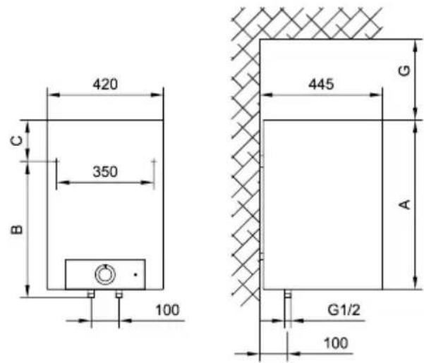
| A B C G | ||||
| OTG 50 N | 690 | 470 | 250 | 210 |
| OTG 80 N | 950 | 735 | 245 | 360 |
Connection and installation dimensions of the water heater [mm]
CONNECTION TO THE WATER SUPPLY
The water heater connections for the inlet and outlet of water are color-coded. The inlet of cold water is marked with blue color, while the hot water outlet is marked with red color.
The water heater can be connected to the water supply in two ways. The closed-circuit pressure system enables several points of use, while the open-circuit gravity system enables a single point of use only. The mixer taps must also be installed in accordance with the selected installation mode.
The open-circuit gravity system requires the installation of a non-return valve in order to prevent the water from draining out of the tank in the event of the water supply running dry or being shut down. This installation mode requires the use of a cross-flow mixer tap. As the heating of water expands its volume, this causes the tap to drip. The dripping cannot be stopped by tightening it further; on the contrary, the tightening can only damage the tap.
The closed-circuit pressure system requires the use of pressure mixer taps. For safety reasons the supply pipe must be fitted with a safety valve or alternatively, a valve of the safety class that prevents the pressure in the tank from exceeding the nominal pressure by more than 0.1 MPa (1 bar). The outlet opening on the relief valve must be equipped with an outlet for atmospheric pressure.
The heating of water in the heater causes the pressure in the tank to increase to the level set by the safety valve. As the water cannot return to the water supply system, this can result in dripping from the outlet of the safety valve. The drip can be piped to the drain by installing a catching unit just below the safety valve. The drain installed below the safety valve outlet must be piped down vertically and placed in an environment that is free from the onset of freezing conditions.
In case the existing plumbing does not enable you to pipe the dripping water from the safety valve into the drain, you can avoid the dripping by installing a 3-litre expansion tank on the inlet water pipe of the boiler.
In order to provide correct operation of the safety valve, periodical inspections of the relief valve must be carried out by the user to eliminate any limescale and check if the safety valve is blocked. To check the valve, open the outlet of the safety valve by turning the handle or unscrewing the nut of the valve (depending on the type of the valve). The valve is operating properly if the water comes out of the nozzle when the outlet is open.
![graph LR 1["1"] --> T["T"] T --> 2["2"] 2 --> 3["3"] 3 --> 4["4"] 4 --> a["a"] a --> b["b"] b --> 5["5"] 5 --> 6["6"] 6 --> 7["7"] 7 --> H["H"]](/content/2026/05/823280/images/fff25987395da789191cb9e5ef9c657299ae453b2e704285ef9dfde686ed7800.jpg)
Closed (pressure) system
![graph TD A["Top Tank"] --> B["T"] B --> C["Valve 9"] C --> D["Valve 8"] D --> E["Valve 7"] C --> F["H"] F --> G["Downward arrow"] style A fill:#f9f,stroke:#333 style B fill:#ccf,stroke:#333 style C fill:#cfc,stroke:#333 style D fill:#fcc,stroke:#333 style E fill:#cff,stroke:#333 style F fill:#ffc,st…](/content/2026/05/823280/images/544fa5752eff9d40e54d4f238dcbc7884effa70537f410acb81949acbab60099.jpg)
Open (non-pressure) system
Legend:
1 - Pressure mixer taps 2 - Expansion tank 3 - Safety valve
a - Test valve
b - Non-return valve
4 - Funnel with outlet connection 5 - Checking fitting
6 - Pressure reduction valve 7 - Closing valve 8 - Non-return valve 9 - Low pressure mixer tap
H - Cold water
T - Hot water
Between the water heater and safety valve, no closing valve may be built in because it could impede the function of the safety valve.
The heater can be connected to the domestic water supply network without a pressure-reducing valve if the pressure in the network is lower than the nominal pressure. If the pressure in the network exceeds the nominal pressure, a pressure-reducing valve must be installed.
Before connecting it to the power supply, the water heater must be filled with water. When filling the heater for the first time, the tap for the hot water on the mixing tap must be opened. When the heater is filled with water, the water starts to run through the outlet pipe of the mixing tap.
CONNECTING THE WATER HEATER TO THE POWER SUPPLY NETWORK
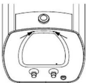
Before connecting to the power supply network, install a power supply cord in the water heater, with a min. diameter of 1.5 mm2 (H05VV-F 3G 1.5 mm2 ). To do this, the protective plate must be removed from the water heater.
Connecting the heater to the power supply network must take place in accordance with the standards for electric appliances. To comply with the national installation regulations, an all poles disconnect switch must be installed between the water heater and the power supply network.
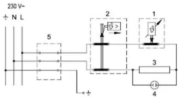
Legend:
1 - Thermostat
2 - Bipolar thermal cut-out
3 - Electric heating element
4 - Pilot lamp
5 - Connection terminal
L - Live conductor
N - Neutral conductor
± - Earthing conductor
Electric installation
CAUTION: Before any intervention into the interior of the water heater, disconnect it from the power supply network!
After connecting to the water and power supply, the heater is ready for use. By turning the thermostat knob, water temperature can be set between 10 °C and 75 °C. We recommend that the knob be set to the position "eco" ensuring the most economic operation of the water heater. This way, the water temperature is maintained at 55 °C while the operation also results in less lime sediment as well as in less heat losses than is the case at higher temperatures. During the operation of an electric heater can hear noise in the water heater. The light indicator shows the operation of the heating element.
When the water heater is not in use for longer periods of time, it should be protected from freezing by setting the temperature to "Do not disconnect the power. Thus the temperature of water is maintained at about 10 °C. Should you choose to disconnect the power, the water heater should be thoroughly drained before the onset of freezing conditions. Water from the heater is drained through the inlet pipe of the heater. For this purpose, a special fitting (T-fitting) must be mounted between the relief valve and the heater inlet pipe, or a discharge tap. The heater can be discharged directly through the relief valve, by rotating the handle or the rotating valve cap to the same position as for checking the operation. Before discharge, make sure the heater is disconnected from the power supply, and open the hot water on the connected mixer tap. After discharging through the inlet pipe, there is still some water left in the water heater. The remaining water will be discharged after removing the heating flange, through the heating flange opening.
The external parts of the water heater can be cleaned with a mild detergent solution. Do not use solvents and abrasives.
With regular service inspections you will ensure faultless functioning and long life of the heater. Tank corrosion warranty applies only if all the prescribed regular inspections of the protective anode wear have been made. The period between regular inspections should not be longer than stated in the warranty certificate. Inspections should be carried out by authorised service providers that will record each inspection on the warranty statement of the product. Upon inspection the service provider will inspect the amount of wear on the anti-corrosion anode and, if necessary, clean the limescale that accumulates depending on the quality, quantity and temperature of the water inside the heater. The service provider will also recommend the date for the next inspection depending on the condition of the heater.
Never try to repair any possible faults of the water heater by yourself, but inform about it the nearest authorised service workshop.
TECHNICAL PROPERTIES OF THE APPLIANCE
| Type OTG 50 N OTG 80 N | |||
| Declared load profile M M | |||
| Energy efficiency class1) | C | C | |
| Water heating energy efficiency (ηwh)1) | [%] | 36,0 36,0 | |
| Annual electricity consumption1) [kWh] | 1 | 427 1428 | |
| Daily electricity consumption2) | [kWh] | 6,692 | 6,698 |
| Thermostat temperature settings | "eco" | "eco" | |
| Value of "smart" | 0 | 0 | |
| Volume | [l] | 49,1 | 78,8 |
| Quantity of mixed water at 40 °CV402) | [l] | 68 | 94 |
| Heating time from 10 °C to 65 °C | [h] | 1:38 | 2:37 |
| Rated pressure | [MPa(bar)] | 0,6(6) | |
| Weight / Filled with water | [kg] | 24/74 | 31/111 |
| Anti-corrosion of tank | enamelled & Mg Anode | ||
| Power of electrical heater | [W] | 2000 | |
| Connection voltage | [V~] | 230 | |
| Protection class | I | ||
| Degree of protection | IP24 | ||
1) EU Regulation 812/2013; EN 50440 2) EN 50440
WE RESERVE THE RIGHT TO MAKE CHANGES THAT DO NOT IMPAIR THE FUNCTIONALITY OF THE DEVICE.
The user manual can also be found at our website http://www.gorenje.com.
WARNINGS
Before connecting to the electrical network, it is necessary to install a connection strip with a minimum cross-section of at least 1.5 mm² (H05VV-F 3G 1.5 mm²) into the water heater. To do this, unscrew the protective cover on the water heater.
The connection of the water heater to the electrical network must be carried out in accordance with the standards for electrical installation. Between the water heater and the permanent installation, a device for disconnecting all poles from the electrical network must be installed in accordance with national installation regulations.
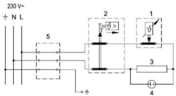
Legend:
1 - Thermostat
2 - Double-pole thermal fuse
3 - Heater
4 - Indicator light
5 - Connection terminals
L - Phase
N - Neutral
± - Ground
Wiring diagram for electrical conductors
WARNING: Before any intervention inside the water heater, always disconnect it from the electrical power supply!
USE AND MAINTENANCE
After connecting to the water supply and electrical network, the water heater is ready for use. By turning the knob on the thermostat, you select the desired temperature from 10 °C to 75 °C.
It is recommended to set the knob to the "eco" position. This setting is the most economical; the water temperature remains around 55 °C, and limescale formation and heat losses will be lower than when set to a higher temperature. During operation of the electric heater, a noise may be heard in the water heater. The operation of the electric heater is indicated by the control lamp.
If you do not intend to use the water heater for a long time, protect its contents from freezing by not disconnecting the electrical power, and set the thermostat knob to the "*" position. At this setting, the water heater will maintain the water temperature at approximately 10 °C. If you disconnect the water heater from the electrical network, you must drain the water from it due to the risk of freezing. The water from the water heater is drained through the inlet pipe. For this purpose, it is advisable to install a special "fitting" (T-piece) or drain valve between the safety valve and the inlet pipe during installation. You can also empty the water heater directly through the safety valve by moving the lever or the rotating cap of the valve to the position as when checking operation. Before draining, disconnect the water heater from the electrical network and then open the hot water tap on the connected mixing faucet. After draining the water through the inlet pipe, a small amount of water remains in the water heater, which flows out when removing the heating flange through the heating flange opening.
Clean the water heater housing with a mild solution of washing powder. Do not use thinners or abrasive cleaning agents.
Regular service inspections will ensure flawless operation and a long service life for the water heater. The warranty for the tank against corrosion is valid only if you have performed the prescribed regular inspections of the wear of the protective anode. The period between individual regular inspections must not be longer than specified in the warranty statement. Inspections must be carried out by an authorized service technician, who will record the inspection on the product warranty card. During the inspection, the wear of the anticorrosion protective anode is checked and, if necessary, limescale that accumulates inside the water heater due to the quality, quantity, and temperature of the consumed water is cleaned. After the inspection, the service department will recommend the date of the next check based on the determined condition.
Please do not repair any malfunctions yourself; instead, notify the nearest service department.
TECHNICAL CHARACTERISTICS OF THE WATER HEATER
| Tip OTG 50 N OTG 80 N | |||
| Određeni profil opterećenja M M | |||
| Razred energetske efikasnosti1) | C | C | |
| Energetsta efikasnost pri zagrevanju vode (ηwh)1) | [%] | 36,0 36,0 | |
| Godišnja potrošnja električne energije1) | [kWh] | 1427 1428 | |
| Dnevna potrošnja električne energije2) | [kWh] | 6,692 6,698 | |
| Podešavanje temperature termostata | "eco" "eco" | ||
| Vrednost "smart" | 0 | 0 | |
| Zapremina | [l] | 49,1 | 78,8 |
| Količina mešane vode na 40 °CV402) | [l] | 68 | 94 |
| Vreme zagrevanja od 10 °C do 65 °C | [h] | 1:38 2:37 | |
| Nominalni pritisak | [MPa(bar)] | 0,6(6) | |
| Masa/napunjen vodom | [kg] | 24/74 | 31/111 |
| Antikorozivna zaštita kotla | emajlirano / Mg anoda | ||
| Snaga električnog grejača | [W] | 2000 | |
| Napon napajanja | [V~] | 230 | |
| Klasa zaštite | I | ||
| Stepen zaštite | IP24 | ||
1) EU Commission Regulation 812/2013; EN 50440 2) EN 50440
WE RESERVE THE RIGHT TO MAKE CHANGES THAT DO NOT AFFECT THE FUNCTIONALITY OF THE APPLIANCE.
The instruction manual is also available on our website at http://www.gorenje.com.



- OTG SLIM SIMPLICITY
- DEAR BUYER, THANK YOU FOR PURCHASING OUR PRODUCT. PRIOR TO THE INSTALLATION AND FIRST USE OF THE ELECTRIC WATER HEATER, PLEASE READ THESE INSTRUCTIONS CAREFULLY
- INSTALLATION
- CONNECTION TO THE WATER SUPPLY
- LEGEND
- BETWEEN THE WATER HEATER AND SAFETY VALVE, NO CLOSING VALVE MAY BE BUILT IN BECAUSE IT COULD IMPEDE THE FUNCTION OF THE SAFETY VALVE
- CONNECTING THE WATER HEATER TO THE POWER SUPPLY NETWORK
- TECHNICAL PROPERTIES OF THE APPLIANCE
- WARNINGS
- USE AND MAINTENANCE
- TECHNICAL CHARACTERISTICS OF THE WATER HEATER
Brand : GORENJE
Model : OTG50SLSIM
Category : Instant water heater and water heater