
KYOTO - Air conditioner DELONGHI - Free user manual and instructions
Find the device manual for free KYOTO DELONGHI in PDF.
Pick your language and provide your email: we'll send you a specifically translated version.
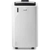
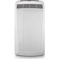
| Product type | Monobloc mobile air conditioner |
| Brand | De'Longhi |
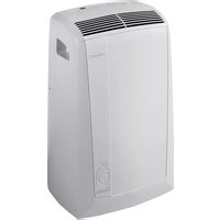
| Model | Kyoto |
| Dimensions (W × D × H) | 45 × 38 × 75 cm |
| Weight | 30 kg |
| Power supply | 220-240 V ~ 50 Hz |
| Cooling power | 9000 BTU/h (2.6 kW) |
| Max power consumption | 1050 W |
| Energy class | A+ |
| Refrigerant | R290 (Propane), 0.180 kg |
| Noise level (max) | 65 dB(A) |
| Water tank capacity | 1.5 L |
| Max air flow | 320 m³/h |
| Functions | Cooling, dehumidification, ventilation, night mode, 24h timer |
| Remote control | Yes, infrared |
| Air filter | Washable filter (every 15 days) |
| Maintenance and cleaning | Clean the filter regularly, drain the tank, clean the condenser with a vacuum cleaner |
| Spare parts | Filters, remote control, exhaust hose, window kit (available in after-sales service) |
| Repairability | Repairability index: 7.6/10 (parts available for 5 years) |
| Safety | Automatic shutdown in case of overheating, frost protection, safety system for refrigerant |
| Warranty | 2 years (parts and labor) |
Frequently Asked Questions - KYOTO DELONGHI
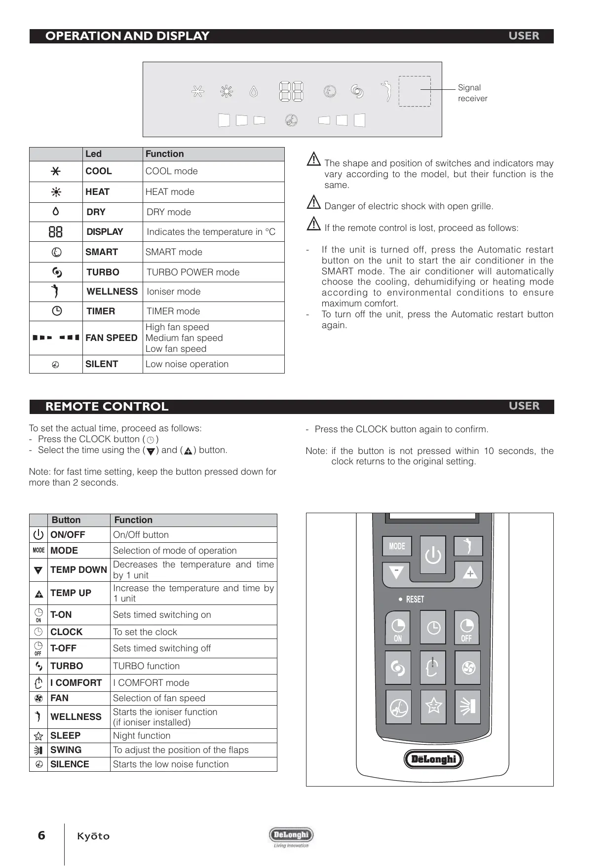
How to install the Delonghi Kyoto air conditioner?
Place the unit near a window or door. Attach the exhaust kit (supplied) in the opening. Plug the unit into a 220-240 V socket. Make sure the hot air hose is not blocked. Refer to the manual for detailed diagrams.
How to clean the air filter of the Delonghi Kyoto?
Turn off the unit and remove the filter located at the back. Wash it with warm soapy water, rinse and dry completely before putting it back. Perform this operation every 2 weeks with frequent use.
What does error code E1 mean on my Kyoto?
The E1 code indicates a fault with the ambient temperature sensor. Check that the sensor is not obstructed and that the unit is not exposed to a direct heat source. If the problem persists, contact customer service.
The water tank fills quickly, is this normal?
Yes, in dehumidification mode or high humidity, the 1.5 L tank can fill in a few hours. You can also install a continuous drain hose (optional accessory). Empty it regularly to avoid automatic shutdown.
Can I use the air conditioner without an exhaust hose?
No, the hot air hose must be connected to the outside to expel hot air. Without it, the unit will cool poorly and may overheat. Use the supplied window kit.
How to set the timer on the Kyoto?
Press the Timer button on the remote control or panel. Use the arrows to set the number of hours (0-24). Confirm with the OK button. The unit will turn off or on automatically.
The noise is loud, what should I do?
The maximum noise level is 65 dB, which is normal for a mobile air conditioner. Make sure the unit is level on a hard surface. Use Night mode to reduce noise (slower fan speed).
How to drain the water tank?
Turn off and unplug the unit. Place a container under the drain plug (at the back, bottom). Unscrew the plug and let the water drain. Screw it back tightly before restarting.
The remote control does not work, why?
Check the batteries (AAA type). Point the remote at the unit's sensor (within 7 m). Clean the sensor. If the problem persists, buy a replacement remote (ref. DLTX).
What periodic maintenance is recommended?
Clean the filter every 2 weeks. Check the exhaust hose once a month. Clean the condenser (fins) with a soft brush vacuum every 6 months. Drain and clean the tank every month during humid periods.
User questions about KYOTO DELONGHI
0 question about this device. Answer the ones you know or ask your own.
Ask a new question about this device
No questions yet. Be the first to ask one.
Download the instructions for your Air conditioner in PDF format for free! Find your manual KYOTO - DELONGHI and take your electronic device back in hand. On this page are published all the documents necessary for the use of your device. KYOTO by DELONGHI.
USER MANUAL KYOTO DELONGHI

Manual assistant
Powered by Anthropic
Waiting for your message
Product information
Brand : DELONGHI
Model : KYOTO
Category : Air conditioner