
US-20x20 - Hi-Fi System TASCAM - Free user manual and instructions
Find the device manual for free US-20x20 TASCAM in PDF.


| Product type | USB audio interface with mic preamp and digital mixer |
| Brand | TASCAM |
| Model | US-20x20 |
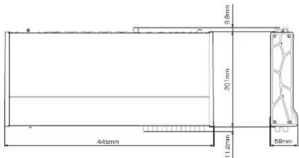
| Dimensions (W × H × D) | 445 × 59 × 222 mm (with standard side panels) |
| Weight | 2.7 kg |
| Power supply | AC adapter (GPE248-120200-Z), input 12 V DC |
| Power consumption | 20 W |
| Sampling frequencies | 44.1 / 48 / 88.2 / 96 / 176.4 / 192 kHz |
| Quantization resolution | 16 / 24 bits |
| Analog inputs | 8 combo XLR/6.35mm jack inputs (MIC/INST IN 1-2, MIC/LINE IN 3-8) + 2 line inputs 6.35mm jack (LINE IN 9-10) |
| Analog outputs | 10 line outputs 6.35mm jack (LINE OUT 1-10) + 2 headphone outputs 6.35mm jack (PHONES 1/2) |
| Digital inputs/outputs | 1 S/PDIF coaxial input, 1 AES/EBU or S/PDIF coaxial output, 1 optical input (ADAT/SMUX), 1 optical output (ADAT/SMUX), 1 BNC word clock input, 1 BNC word clock output |
| MIDI | 1 DIN 5-pin input, 1 DIN 5-pin output |
| USB connectivity | USB 3.0 type B (compatible USB 2.0) |
| Phantom power | +48 V per group of 4 channels (separate switches for IN 1-4 and IN 5-8) |
| Operating modes | Mic preamp (MIC PRE), Audio interface (AUDIO I/F), Digital mixer (MIXER) |
| Dedicated software | Settings Panel for Windows and Mac, ASIO/WDM/Core Audio driver |
| Supported operating systems | Windows 7, 8/8.1, 10 (32/64-bit); Mac OS X 10.8.5, 10.9.5, 10.10.1+; iOS 7+ (via Lightning adapter) |
| Operating temperature | 5 °C to 35 °C |
| Maintenance and cleaning | Wipe gently with a dry, soft cloth. Do not use chemicals, thinner, alcohol. |
| Safety | Do not expose to water, do not block openings, use only the supplied adapter, unplug during storms. |
Frequently Asked Questions - US-20x20 TASCAM
User questions about US-20x20 TASCAM
0 question about this device. Answer the ones you know or ask your own.
Ask a new question about this device
Download the instructions for your Hi-Fi System in PDF format for free! Find your manual US-20x20 - TASCAM and take your electronic device back in hand. On this page are published all the documents necessary for the use of your device. US-20x20 by TASCAM.
USER MANUAL US-20x20 TASCAM
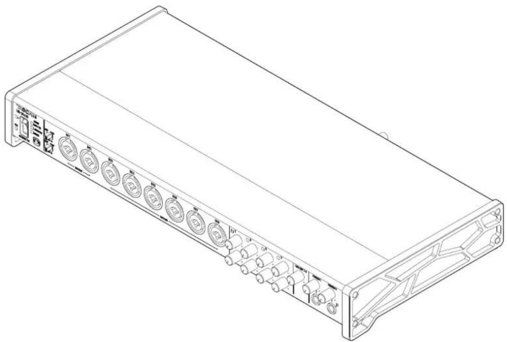
USB Audio MIDI Interface with Mic Pre/Mixer
natural_image
Line drawing of a rectangular electronic device with multiple ports and connectors (no text or symbols)OWNER'S MANUAL
ENGLISH
MODE D'EMPLOI
FRANÇAIS
MANUAL DEL USUARIO
ESPAÑOL
BEDIENUNGSANLEITUNG
DEUTSCH
• TASCAM is a trademark of TEAC CORPORATION, registered in the U.S. and other countries.
- Microsoft, Windows and Windows Vista are either registered trademarks or trademarks of Microsoft Corporation in the United States and/or other countries.
- Apple, Mac, Mac OS X, and Lightning are trademarks of Apple Inc.
- IOS is a trademark or registered trademark of Cisco in the U.S. and other countries and is used under license.
• ASIO is a trademark and software of Steinberg Media Technologies GmbH.
- Blackfin® and the Blackfin logo are registered trademarks of Analog Devices, Inc.
- Other company names, product names and logos in this document are the trademarks or registered trademarks of their respective owners.
ティアック株式会社
http://tascam.jp/
1834 Gage Road, Montebello, California 90640 USA
TEAC MEXICO, S.A. de C.V.
http://teacmexico.net/
Phone: +52-55-5010-6000
2 Huxley Road, Surrey Research Park, Guildford, GU2 7RE,
United Kingdom
TEAC EUROPE GmbH
http://tascam.eu/
Phone: +49-611-71580
Room 817, Block A, Hailrun Complex, 6021 Shennan Blvd.,
Futian District, Shenzhen 518040, China
Owner's Manual
IMPORTANT SAFETY PRECAUTIONS
For U.S.A.
INFORMATION TO THE USER
This equipment has been tested and found to comply with the limits for a Class B digital device, pursuant to Part 15 of the FCC Rules. These limits are designed to provide reasonable protection against harmful interference in a residential installation. This equipment generates, uses, and can radiate radio frequency energy and, if not installed and used in accordance with the instruction manual, may cause harmful interference to radio communications. However, there is no guarantee that interference will not occur in a particular installation. If this equipment does cause harmful interference to radio or television reception, which can be determined by turning the equipment off and on, the user is encouraged to try to correct the interference by one or more of the following measures.
a) Reorient or relocate the receiving antenna.
b) Increase the separation between the equipment and receiver.
c) Connect the equipment into an outlet on a circuit different from that to which the receiver is connected.
d) Consult the dealer or an experienced radio/TV technician for help.
CAUTION
Changes or modifications to this equipment not expressly approved by TEAC CORPORATION for compliance could void the user's authority to operate this equipment.
For Canada
THIS CLASS B DIGITAL APPARATUS COMPLIES WITH CANADIAN ICES-003.
CET APPAREIL NUMERIQUE DE LA CLASSE B EST CONFORME A LA NORME NMB-003 DU CANADA.
DECLARATION OF CONFORMITY
We, TEAC EUROPE GmbH. Bahnstrasse 12, 65205 Wiesbaden-Erbenheim, Germany declare in own responsibility, the TEAC product described in this manual is in compliance with the corresponding technical standards.

Declaration of Conformity
Responsible party: TEAC AMERICA, INC.
Address: 1834 Gage Road, Montebello, California, U.S.A.

Telephone number: 1-323-726-0303
This device complies with Part 15 of the FCC Rules. Operation is subject to the following two conditions: (1) this device may not cause harmful interference, and (2) this device must accept any interference received, including interference that may cause undesired operation.
IMPORTANT SAFETY INSTRUCTIONS
1 Read these instructions.
2 Keep these instructions.
3 Heed all warnings.
4 Follow all instructions.
5 Do not use this apparatus near water.
6 Clean only with dry cloth.
7 Do not block any ventilation openings. Install in accordance with the manufacturer's instructions.
8 Do not install near any heat sources such as radiators, heat registers, stoves, or other apparatus (including amplifiers) that produce heat.
9 Do not defeat the safety purpose of the polarized or grounding-type plug. A polarized plug has two blades with one wider than the other. A grounding type plug has two blades and a third grounding prong. The wide blade or the third prong are provided for your safety. If the provided plug does not fit into your outlet, consult an electrician for replacement of the obsolete outlet.
10 Protect the power cord from being walked on or pinched particularly at plugs, convenience receptacles, and the point where they exit from the apparatus.
11 Only use attachments/accessories specified by the manufacturer.
12 Use only with the cart, stand, tripod, bracket, or table specified by the manufacturer, or sold with the apparatus. When a cart is used, use caution when moving the cart/apparatus combination to avoid injury from tip-over.
13 Unplug this apparatus during lightning storms or when unused for long periods of time.
14 Refer all servicing to qualified service personnel. Servicing is required when the apparatus has been damaged in any way, such as power-supply cord or plug is damaged, liquid has been spilled or objects have fallen into the apparatus, the apparatus has been exposed to rain or moisture, does not operate normally, or has been dropped.
- The apparatus draws nominal non-operating power from the AC outlet with its POWER or STANDBY/ON switch not in the ON position.
- The mains plug is used as the disconnect device, the disconnect device shall remain readily operable.
- Caution should be taken when using earphones or headphones with the product because excessive sound pressure (volume) from earphones or headphones can cause hearing loss.
- If you are experiencing problems with this product, contact TEAC for a service referral. Do not use the product until it has been repaired.
CAUTION
• Do not expose this apparatus to drips or splashes.
- Do not place any objects filled with liquids, such as vases, on the apparatus.
- Do not install this apparatus in a confined space such as a book case or similar unit.
- The apparatus should be located close enough to the AC outlet so that you can easily grasp the power cord plug at any time.
- If the product uses batteries (including a battery pack or installed batteries), they should not be exposed to sunshine, fire or excessive heat.
- CAUTION for products that use replaceable lithium batteries: there is danger of explosion if a battery is replaced with an incorrect type of battery. Replace only with the same or equivalent type.
■or European Customers
Disposal of electrical and electronic equipment
(a) All electrical and electronic equipment should be disposed of separately from the municipal waste stream via designated collection facilities appointed by the government or the local authorities.
(b) By disposing of the electrical and electronic equipment correctly, you will help save valuable resources and prevent any potential negative effects on human health and the environment.
(c) Improper disposal of waste equipment can have serious effects on the environment and human health as a result of the presence of hazardous substances in electrical and electronic equipment.
(d) The crossed out wheeled dust bin symbol indicates that electrical and electronic equipment must be collected and disposed of separately from household waste.
(e) The return and collection systems are available to the end users. For more detailed information about disposal of old electrical and electronic equipment, please contact your city office, waste disposal service or the shop where you purchased the equipment.
Contents
IMPORTANT SAFETY PRECAUTIONS ....3
IMPORTANT SAFETY INSTRUCTIONS....3
Introduction 5
Note about the Reference Manual....5
Included items....5
Precautions for placement and use....5
Using the TEAC Global Site 5
Beware of condensation....5
Cleaning the unit....5
User registration 5
Names and functions of parts 6
Front panel 6
Rear panel....7
Installing the dedicated software 8
Installing the Windows driver....8
Installing the Mac Settings Panel 9
Connecting the power 10
Changing the outlet plug....10
Connecting with a computer....10
Making computer settings....11
Making settings on the MIXER screen 11
Making settings on the INTERFACE screen....12
Making settings on the OUTPUT SETTING screen ....12
Examples of connections with other equipment....13
Connecting with iOS devices....13
Adjusting the input sound....13
Overview of operation modes....14
Using the unit as a microphone preamp....14
Using the unit as an audio interface .... 14
Using the unit as a digital mixer ....14
Changing sampling frequency 14
Input and output channels in mic preamp mode.....14
Troubleshooting....15
Specifications....16
Ratings 16
Analog inputs....16
Analog outputs....17
Digital audio input/output ratings 17
Control input/output ratings....17
Audio performance....17
Computer system requirements ....17
Supported audio drivers 18
General....18
Dimensional drawings 18
Introduction
Thank you very much for purchasing the TASCAM US-20x20 USB Audio MIDI Interface with Mic Pre/Mixer.
Before connecting and using this unit, please take time to read this manual thoroughly to ensure you understand how to properly set it up and connect it, as well as the operation of its many useful and convenient functions. After you have finished reading this manual, please keep it in a safe place for future reference.
Before connecting this unit to a computer, you must download and install dedicated software on the computer.
This product has a Blackfin ^® processor made by Analog Devices, Inc.
Note about the Reference Manual
This Owner's Manual explains each of the functions of this unit. Please see the Reference Manual for detailed information about each of the functions.
You can download the Reference Manual from the TEAC Global Site (http://teac-global.com/).
Included items
This product includes the following items.
Keep the box and packing materials for transportation in the future.
Please contact TASCAM Customer Support (see page 2) if any of these items are missing or have been damaged during transportation.
● Main unit....×1
● AC adapter (GPE248-120200-Z)
(with output plug A/B for replacement)....× 1
- USB 2.0 cable....×1
- USB 3.0 cable....x 1
● Hex key....×1
- Rack mount angles....×2
- Rack mount angle attachment screws....×4
- Owner's Manual (this document) including warranty ..x 1
CAUTION
• Always use the included AC adapter (GPE248-120200-Z) when using this unit. Never use the included AC adapter with any other device. Doing so could cause damage, fire or electric shock.
- Which of the included cables (USB 2.0 or USB 3.0) can be connected depends on the computer and operating system being used. (See "Connecting with a computer" on page 10.)
NOTE
The included AC adapter (GPE248-120200-Z) is shipped with alternate outlet plugs. Please see "Changing the outlet plug" in "4 – Preparation" in the Reference Manual for instructions about how to do this.
Precautions for placement and use
● The operating temperature range of this unit is 5–35 °C.
- Do not install this unit in the following types of locations. Doing so could make the sound quality worse or cause malfunction.
Locations with frequent vibrations
Next to a window or in another location exposed to direct sunlight
Near heating equipment or in other locations that become very hot
Extremely cold places
Places with bad ventilation or high humidity Very dusty locations
● To enable good heat dissipation, do not place anything on top of the unit.
- Do not place the unit on top of a power amplifier or other device that generates heat.
- When mounting this unit in a rack, leave at least 1U of space open above it in the rack.
Using the TEAC Global Site
You can download the Owner's Manual and the Reference Manual necessary for this unit from the TEAC Global Site (http://teac-global.com/).
- Open the TEAC Global Site (http://teac-global.com/).
- In the TASCAM Downloads section, click the desired language to open the Downloads website page for that language.
NOTE
If the desired language does not appear, click Other Languages.
- Click the product name in the "Search by Model Name" section to open the Downloads page for that product.
- Select and download the Owner's Manual that are needed.
Beware of condensation
Condensation could occur if the unit is moved from a cold place to a warm place, it is used immediately after a cold room has been heated or it is otherwise exposed to a sudden temperature change.
To prevent this, or if this occurs, let the unit sit for one or two hours at the new room temperature before using it.
Cleaning the unit
To clean the unit, wipe it gently with a soft dry cloth. Do not wipe with chemical cleaning cloths, benzene, thinner, alcohol or other chemical agents. Doing so could damage the surface or cause discoloration.
User registration
Customers in the USA, please visit the TASCAM website (http://tascam.com/) to register as a user online.
Front panel
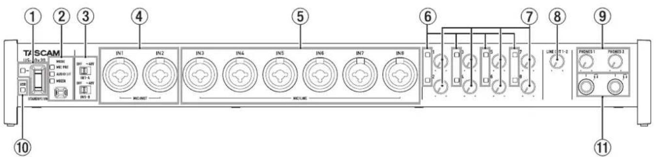
① STANDBY/ON switch and indicator
Press to turn the unit on and to put it into standby. The STANDBY/ON indicator lights green when the unit is on.
② MODE button and indicators
Use to change the operation mode. (See "Overview of operation modes" on page 14.)
MIC PRE
This lights when the unit is operating as a microphone preamp.
AUDIO I/F
This lights when the unit is operating as an audio interface.
MIXER
This lights when the unit is operating as a digital mixer.
③ Phantom power switches
Use these switches to provide +48V phantom power to the IN1-IN4 and IN5-IN8 jacks.
You can change the Phantom power setting for four channels of inputs at a time. Phantom power is supplied when the switch is set to +48V.
④ MIC/INST IN1-IN2 jacks (BALANCED / UNBALANCED)
These analog inputs are XLR/TRS combo jacks.
These inputs support high impedance input, including direct guitar input.
⑤ MIC/LINE IN3-IN8 jacks (BALANCED)
These analog inputs are XLR/TRS combo jacks. These jacks support line input from audio equipment and keyboards, for example.
⑥ Signal/overload indicators
These light red when signals are about to distort (-1 dBFS) and the light green when signals are being input (-32 dBFS or higher).
⑦ Gain knobs
Use to adjust the output levels of the IN1-IN8 jacks.
⑧ LINE OUT 1-2 knob
Use to adjust the output level of the LINE OUT 1-2 jacks on the back of the unit.
⑨ PHONES 1/2 knobs
Use to adjust the output levels of the PHONES 1/2 jacks.
CAUTION
Before connecting headphones to a jack, minimize its PHONES knob. Failure to do so might cause sudden loud noises, which could harm your hearing or result in other trouble.
⑩ USB indicator
This lights orange when the USB connection is enabled.
⑪ PHONES 1/2 jacks
Use these standard stereo jacks to connect stereo headphones. The same signal is output from the LINE OUT 1/2 jacks.
Use an adapter to connect headphones with a mini plug.
Rear panel
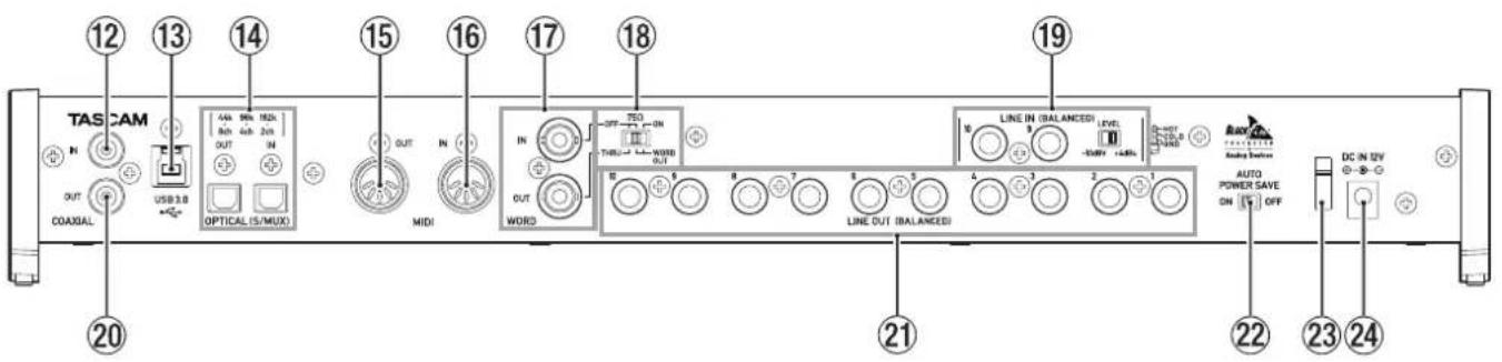
⑫ COAXIAL IN jack
This digital audio input jack complies with the S/PDIF standard.
⑬ USB port
Use the included USB cable to connect the unit to a computer or iOS device (supports USB 2.0/3.0).
CAUTION
- Which of the included cables (USB 2.0 or USB 3.0) can be connected depends on the computer and operating system being used. (See "Connecting with a computer" on page 10.)
• USB 1.1 is not supported.
⑭ OPTICAL (S/MUX) IN/OUT connectors
These input and output multichannel digital audio in optical format.
44.1, 48, 88.2, 96, 176.4 and 192kHz sampling frequencies are supported.
SMUX2 is supported for formats up to 88.2/96 kHz, and SMUX4 is supported for formats up to 176.4/192 kHz.
⑮ MIDI OUT jack
This 5-pin DIN is a standard MIDI output jack. This outputs MIDI signals.
⑯ MIDI IN jack
This 5-pin DIN is a standard MIDI input jack. Use this to input MIDI signals.
⑰ WORD IN/OUT connectors
These BNC connectors are for the input and output of word clock and video reference signals. Word clock signals of 44.1, 48, 88.2, 96, 176.4 and 192 kHz can be input and output.
CAUTION
If a digital system has multiple word clock masters, serious problems, including damage to equipment, could occur.
⑱ 75Ω ON/OFF/THRU/WORD OUT switch
Use this switch to make the following settings.
- Whether or not the WORD IN connector has 75Ω termination
- WORD output THRU/OUT setting (OUT is for WORD only)
⑲ LINE IN 9-10 (BALANCED) jacks and LEVEL switch
These standard TRS jacks are line inputs. Use the LEVEL switch to set the nominal level to -10dBV or +4dBu.
⑳ COAXIAL OUT jack
This digital audio output connector supports the AES/EBU and S/PDIF standards. Set the digital signal format on the "INTERFACE" page of the Settings Panel.
②1 LINE OUT (BALANCED) 1–10 jacks
These standard TRS jacks are line outputs. The nominal output level is +4 dBu. (Tip: HOT, Ring: COLD, Sleeve: GND)
② AUTO POWER SAVE switch
Use this switch to have the unit turn itself off automatically (start standby) when operating in mic preamp mode if no input signal above -60 dBFS is detected for 30 minutes.
CAUTION
If you want to turn the unit on again after it has turned itself off (started standby) automatically, press the STANDBY/ON button once, wait at least 8 seconds and then press the STANDBY/ON button again.
②3 Cord holder
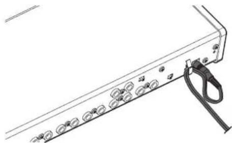
Hook the cord of the included AC adapter here to prevent accidental disconnection.
⑳ DC IN 12V connector
Connect the included AC adapter (GPE248-120200-Z) here.
Installing the dedicated software
To use this unit with a computer, dedicated software must be installed on the computer.
Download the latest software for the operating system you are using from the TEAC Global Site (http://teac-global.com/).
● To use this unit with a Windows computer, install the Windows driver.
When you install the Windows driver, the Windows Settings Panel application will be installed at the same time.
● To use this unit with a Mac, install the Mac Settings Panel application.
The standard OS driver will be used.
- When using this unit with an iOS device, the standard OS driver will be used, so there is no need to install dedicated software.
CAUTION
Before starting to installer software, quit other applications.
Installing the Windows driver
CAUTION
- Complete installation of the Windows driver on the computer before connecting the unit to it with the USB cable.
• If you already connected the unit to the computer using the USB cable before installing the Windows driver and the Found New Hardware Wizard launched, close the message and disconnect the USB cable.
■Windows driver installation procedures
- Download the latest Windows driver for the operating system you are using from the TEAC Global Site (http://teac-global.com/) and save it on the computer to be used with the unit.
- Open the saved Windows driver (zip file) on, for example, the computer desktop.
- Double-click the "US-20x20_installer" file in the folder that appears after uncompression to automatically launch the installation software.
- When a "Security Warning" or "User Account Control" screens appear, click the "Yes" button.
- When the InstallShield Wizard screen appears, click the "Next (N)" button.
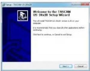
- Read the contents of the License Agreement, and select "Agree (A)" if you agree to the terms. Then, click the "Next (N)" button.
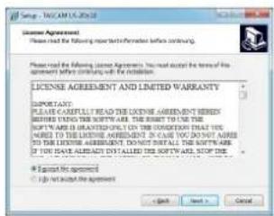
- Click the "Install (I) button."
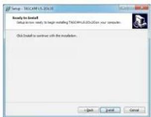
- Next, click the "Install (I)" button to start installation.
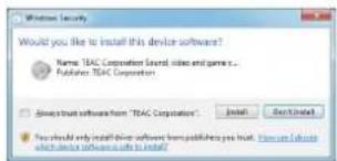
- The following screen appears when installation has completed. Click the "Finish (F)" button.
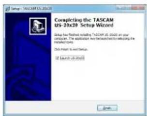
The installer will quit and the Windows Settings Panel will launch.
NOTE
After installing the driver, the device driver will be installed the first time the unit is connected by USB. At this time, Windows will automatically search Windows Update, and it may take some time to recognize the unit connection. If the unit is still not recognized after some time, open the software installation screen from the message area at the bottom right of the computer display, and click "Skip Obtaining Drivers From Windows Update" to cancel the search.
Installing the Mac Settings Panel
NOTE
• Install the Mac Settings Panel on the computer before connecting the unit to it with the USB cable.
- Depending on the Gatekeeper setting, a warning message might appear during installation. For information about Gatekeeper, see "Note about Gatekeeper" in "3 – Installation" of the Reference Manual.
■Mac Settings Panel installation procedures
- Download the latest Mac Settings Panel for the operating system you are using from the TEAC Global Site (http://teac-global.com/) and save it on the computer to be used with the unit.
- Double-click "US-20x20_Installer.dmg", which is the saved disk image file for the Mac Settings Panel, and double-click "US-20x20.pkg" inside the folder that opens.

US-20x20.pkg
NOTE
Depending on the computer's settings, the downloaded zip file might not have opened automatically. In this case, open the zip file first and then double-click the disk image file.
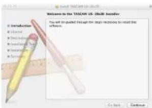
- When the installer starts, click the "Continue" button.
- Next, select the desired language and click the "Continue" button.
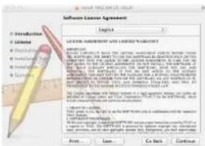
- Click the "Read License" button and check the contents of the Software License Agreement. If you agree to the contents, click "Agree".
Then, click the "Next" button.

- Next, click the "Install" button to start installation.
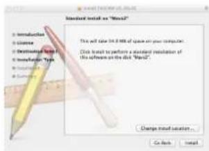
- The following screen appears when installation has completed.
Click the "Close" button.
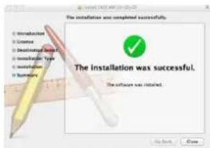
The Mac Settings Panel will launch.
Connecting the power
Use the included AC adapter to connect a power supply to the unit as shown below.
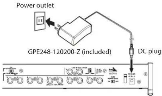
In order to prevent the cord from becoming disconnected during use, wrap it around the cord holder when connecting it.
natural_image
Diagram of a server rack with attached cable and connector (no text or symbols)CAUTION
Always use the AC adapter (GPE248-120200-Z) that was shipped with the unit. Using a different AC adapter could cause malfunction, overheating, fire or other problems.
NOTE
The AC adapter for the unit includes two types of outlet plugs. Attach the type of plug that matches the power outlet that you are using. See "Changing the outlet plug" on page 10.
Changing the outlet plug
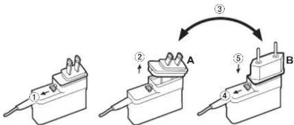
flowchart
graph TD
    A["Component A"] -->|②| B["Component B"]
    B -->|③| C["Component C"]
    C -->|④| D["Component D"]
    D -->|⑤| E["Component E"]
① Move the latch on the AC adapter in the direction of the arrow.
② Pull off the outlet plug.
③ Replace it with the other outlet plug (A or B).
④ Move the latch on the AC adapter in the direction of the arrow again.
⑤ Attach the outlet plug to the AC adapter.
After changing the outlet plug, confirm that it is not loose or crooked and that everything is normal before plugging it into an outlet
CAUTION
Do not use the adapter if there is anything abnormal about the plug after changing it. Use when the plug is abnormal could cause fire or electric shock. Contact the retailer where you purchased the unit or a TEAC service center (on the back cover) to request repair.
Connecting with a computer
Two types of USB cables (USB 2.0 and USB 3.0) are included with this unit.
Select one of the included USB cables according to the computer and operating system being used and use it to connect the unit to a computer USB 2.0 or USB 3.0 port.
NOTE
A USB2.0 speed connection will be used if the unit is connected to a USB3.0 port on the computer using a USB2.0 cable.
Check the TEAC Global Site (http://teac-global.com/) for the latest information about supported operating systems.
Windows
| Supported operating systems | USB standard | Connected USB cable | |
| USB 2.0 | USB 3.0 | ||
| Windows 10 32-bit | √ | √* | USB 3.0 cable* |
| Windows 10 64-bit | √ | √* | USB 2.0 cable |
| Windows 8 (including 8.1) 32-bit | √ | USB 2.0 cable | |
| Windows 8 (including 8.1) 64-bit | √ | ||
| Windows 7 32-bit SP1 or later | √ | USB 2.0 cable | |
| Windows 7 64-bit SP1 or later | √ | ||
* Connect with the included USB 3.0 cable to use at USB 3.0 speed.
Mac
| Supported operating systems | USB standard | Connected USB cable | |
| USB 2.0 | USB 3.0 | ||
| OS X Yosemite (10.10.1 or later) | √ | - USB | 2.0 cable |
| OS X Mavericks (10.9.5) | √ | - USB | 2.0 cable |
| OS X Mountain Lion (10.8.5) | √ | - USB | 2.0 cable |
Making computer settings
NOTE
In order to enable the computer to handle digital audio signals smoothly, other loads on the computer should be minimized as much as possible. We recommend that you quit unneeded applications before use.
Making settings on the MIXER screen
Launch the Settings Panel software.
Windows
From "All Apps" (All Programs), select "US-20x20 Settings Panel" under TASCAM.
Mac OS X
Select "US-20x20 Settings Panel" from Applications and launch it to open the Settings Panel on the computer display. Click the MIXER tab on the Settings Panel to open the MIXER page as shown below.
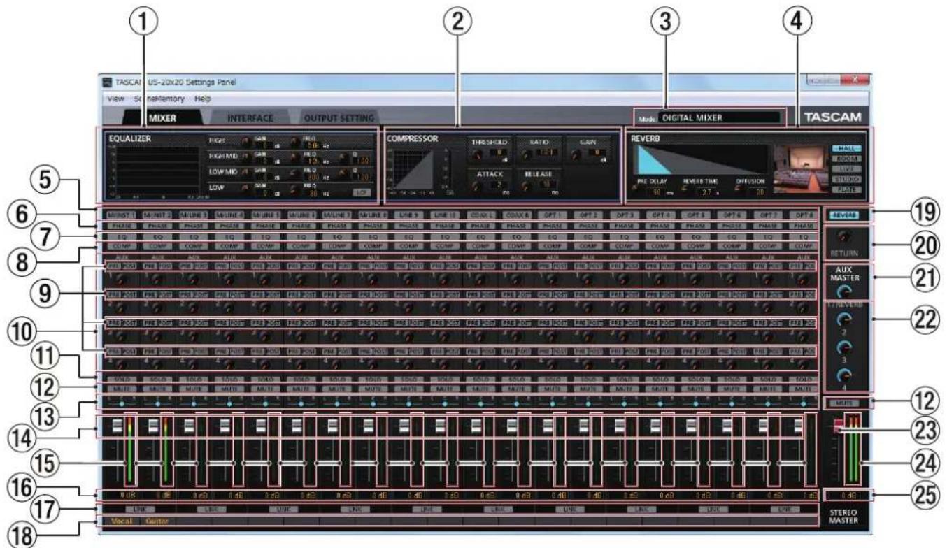
Windows Settings Panel MIXER page
NOTE
When the unit is in MIC PRE mode, clicking the MIXER tab will not open the MIXER page.
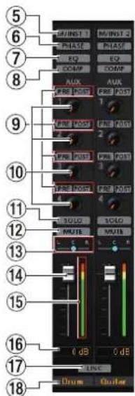
① EQUALIZER
Equalizer settings are shown for the channel selected using its Select button (⑤).
② COMPRESSOR
Compressor settings are shown for the channel selected using its Select button (⑤).
③ Mode
This shows the operation mode of the unit set using the MODE button on its front panel.
④ REVERB
This shows the reverb settings.
⑤ Select buttons
Activate one of these buttons to show the equalizer and compressor settings for that channel in 1 and 2.
⑥ PHASE buttons
Click a PHASE button to reverse the phase of that channel. Lit buttons show the channels that have this function activated.
⑦ EQ buttons
Click an EQ button to activate the equalizer for that channel. Lit buttons show the channels that have this function activated.
⑧ COMP buttons
Click a COMP button to activate the compressor for that channel. Lit buttons show the channels that have this function activated.
⑨ Effect AUX selection buttons
⑩ AUX 1–4 knobs and indicators
⑪ SOLO buttons
⑫ MUTE buttons
⑬ Pan sliders
⑭ Channel faders
⑮ Channel level meters
⑯ Fader level display areas
⑰ LINK buttons
⑱ Channel notes
⑲ REVERB button
⑳ RETURN knob and indicator
②1 AUX MASTER 1/REVERB knob and indicator
22 AUX MASTER 2-4 knobs and indicators
②3 STEREO MASTER fader
⑳ STEREO MASTER level meters
⑳ STEREO MASTER fader level display areas
For details about other settings, see "MIXER page" in "6 – Using the Settings Panel" of the Reference Manual.
Making settings on the INTERFACE screen
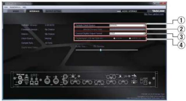
Windows Settings Panel "INTERFACE" page
For details about other settings, see "INTERFACE page" in "6 - Using the Settings Panel" of the Reference Manual. (See "Note about the Reference Manual" on page 5.)
■etting the sample clock source
- Click the "INTERFACE" tab on the Settings Panel to open the "INTERFACE" page.
- Click Sample Clock Source (①) on the "INTERFACE" page to set the sample clock source.
Options: COAXIAL, OPTICAL, WORD, INTERNAL
NOTE
When set to "COAXIAL", "OPTICAL" or "WORD", if no signal is input into the corresponding input jack or the unit becomes unable to synchronize, "unlock" will appear as the "Digital Input Status" in the status display area and the unit's MODE indicator will blink.
■etting the sampling frequency used when set to INTERNAL
Set the Internal Sample Rate item (②) to the sampling
frequency to be used when the Sample Clock Source (①) is set to INTERNAL.
- Click the "INTERFACE" tab on the Settings Panel to open the "INTERFACE" page.
- Click the Internal Sample Rate item (②) on the "INTERFACE" page and set the sampling frequency of the unit's internal clock.
Options: 44.1kHz, 48kHz, 88.2kHz, 96kHz, 176.4kHz, 192kHz
NOTE
When the unit is in MIC PRE or AUDIO I/F operation mode, you cannot set the Internal Sample Rate.
■etting the digital output format
- Click the "INTERFACE" tab on the Settings Panel to open the "INTERFACE" page.
- Click Coaxial Digital Output Format (②) on the "INTERFACE" page to set the digital output format.
Options: S/PDIF, AES/EBU
■etting the digital input destination (only when 176.4kHz/192kHz)
- Click the "INTERFACE" tab on the Settings Panel to open the "INTERFACE" page.
- Click the Digital Input (176.4k/192kHz) item (④) on the "INTERFACE" page and set the digital input destination. Options: COAXIAL, OPTICAL 1/2
Making settings on the OUTPUT SETTING screen
When the unit is in "AUDIO I/F" or "MIXER" mode, you can set the signals output to each output jack on the "OUTPUT SETTING" page.
For details about each operation mode, see (See "Overview of operation modes" on page 14.)
![Logic vs. audio setting Name: Supplementary Help MACHINE OUTPUT SETTING AUDIO INTERFACE TASCAM Analog Input Audio Signal Output Digital Input VREF 1.0 OFF 1.0 Time CONTINUING [LOW] 0 1 2 3](/content/2026/05/813335/images/98a074d48f36511ae9d5c1f7121d3ed16c8ddce0a1df7a6540c878c634dd6f36.jpg)
"AUDIO I/F" mode example
NOTE
- When the unit is in MIC PRE mode, you cannot change settings in the output selection area on the "OUTPUT SETTING" page.
- For details about other settings, see "OUTPUT SETTING page" in "6 – Using the Settings Panel" of the Reference Manual. (See "Note about the Reference Manual" on page 5.)
Examples of connections with other equipment
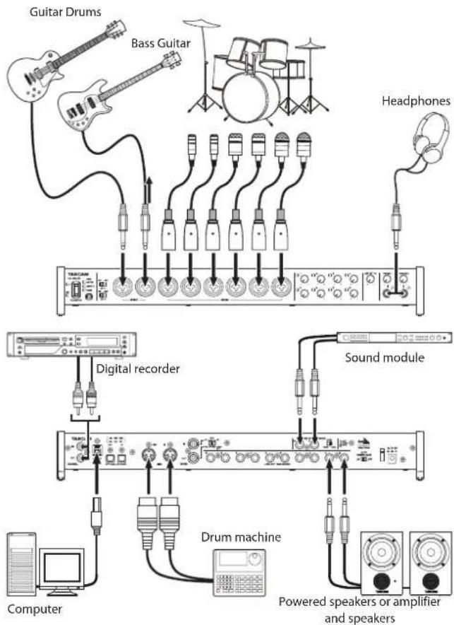
flowchart
graph TD
    A["Guitar Drums"] --> B["Bass Guitar"]
    B --> C["Headphones"]
    C --> D["DC"]
    D --> E["Digital recorder"]
    E --> F["Computer"]
    D --> G["Sound module"]
    G --> H["Drum machine"]
    H --> I["Powered speakers or amplifier and speakers"]
    style A fill:#f9f,stroke:#333
    style B fill:#ccf,stroke:#333
    style C fill:#cfc,stroke:#333
    style D fill:#fcc,stroke:#333
    style E fill:#cff,stroke:#333
    style F fill:#ffc,stroke:#333
    style G fill:#fcc,stroke:#333
    style H fill:#ffc,stroke:#333
    style I fill:#fcc,stroke:#333
Example using a US-20x20
CAUTION
• Before making connections, turn this unit and all equipment to be connected off (standby).
• The phantom power switches set four input channels at a time. Do not set phantom power to +48V when connecting a mic that does not require phantom power.
- Before changing a phantom power switch setting, set the LINE OUT 1–2 and PHONES 1/2 knobs to their minimum values. Failure to do so could cause sudden loud noises from monitoring equipment, and this could damage equipment or harm hearing.
- Do not connect or disconnect mics when a PHANTOM switch is set to +48V. Doing so could cause a loud noise and might damage this unit and connected equipment.
- Set the PHANTOM switch to +48V only when using a condenser microphone that requires phantom power. Turning phantom power on when a dynamic mic or other mic that does not require it is connected could damage this unit and connected equipment.
- When using condenser mics that require phantom power and dynamic mics together, be sure to use balanced dynamic mics. Unbalanced dynamic mics cannot be used when phantom power is enabled.
• Supplying phantom power to some ribbon mics will break them. If you are unsure, do not supply phantom power to a ribbon mic.
Connecting with iOS devices
You can use a Lightning to USB Camera Adapter* to connect the unit to an iOS device and use it as an interface with that device.
*You will need to prepare an Apple genuine Lightning to USB Camera Adapter (sold separately).
NOTE
When connected, this unit will not provide power to the iOS device.
Adjusting the input sound
Analog audio signals input into this device from mics, guitars, keyboards and other audio equipment can be converted into digital signals and transmitted to the computer via USB. In addition, you can monitor audio signals by connecting powered monitor speakers or headphones to this unit.
Use the various controls as necessary.
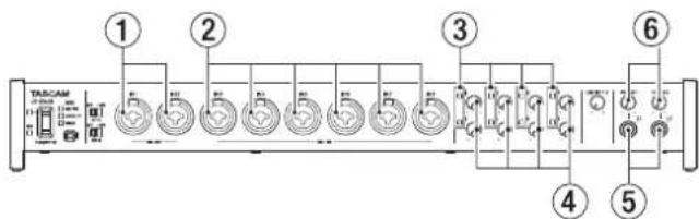
Adjust the analog input levels of the MIC/INST IN 1-2 jacks (①) and MIC/LINE IN 3-8 jacks (②) using their gain knobs (④) so that their signal/overload indicators (③) do not light.
To monitor the sound using headphones, connect headphones to the PHONES 1/2 jacks (⑤) and adjust the PHONES 1/2 knobs (⑥).
NOTE
Check the following if you cannot hear the input sounds.
- Use the PHONES 1/2 knobs on the front panel to adjust the output levels of the PHONES 1/2 jacks.
- Use the LINE OUT 1-2 knob on the front panel to adjust the output levels of the LINE OUT 1-2 jacks.
Overview of operation modes
Press the MODE button on the front of the unit to switch the operation mode.
The MODE indicator lights for the currently active operation mode.
This unit has the following three operation modes.
MIC PRE
The unit functions as a microphone preamp.
AUDIO I/F
The unit functions as an audio interface.
MIXER
The unit functions as a digital mixer.
Using the unit as a microphone preamp
- Press the MODE button on the front of the unit to set it to MIC PRE.
"MIC PRE" appears in the MODE display area at the top of the Settings Panel.
- Click the "OUTPUT SETTING" tab on the Settings Panel to open the "OUTPUT SETTING" page.
NOTE
When the unit is in MIC PRE mode, you cannot make settings on the "OUTPUT SETTING" page.
Using the unit as an audio interface
- Press the MODE button on the front of the unit to set it to AUDIO I/F.
"AUDIO INTERFACE" appears in the MODE display area at the top of the Settings Panel.
-
Click the "OUTPUT SETTING" tab on the Settings Panel to open the "OUTPUT SETTING" page.
-
Click the output signal selection area on the "OUTPUT SETTING" page, and set the signal output from each output jack.
Options: MASTER L/MASTER R, AUX 1 – AUX 4, COMPUTER 1 – COMPUTER 20
- The signal destination selected in step 3 will be shown in the connection display area on the "OUTPUT SETTING" page.
Using the unit as a digital mixer
- Press the MODE button on the front of the unit to set it to MIXER.
"DIGITAL MIXER" appears in the MODE display area at the top of the Settings Panel.
-
Click the "OUTPUT SETTING" tab on the Settings Panel to open the "OUTPUT SETTING" page.
-
Click the output signal selection area on the "OUTPUT SETTING" page, and set the signal output from each output jack.
Options: MASTER L/MASTER R, AUX 1 – AUX 4
- The signal destination selected in step 3 will be shown in the connection display area on the "OUTPUT SETTING" page.
Changing sampling frequency
■h mic preamp and digital mixer modes
Use the following settings to change the sampling frequency (44.1 kHz by default) in mic preamp and digital mixer modes.
Windows
Control Panel → Sound window → Speakers TASCAM
US-20x20 → Properties (p) → US-20x20 Properties
Advanced tab → Default Format
Mac
Applications folder → Utilities folder → Audio MIDI Setup
→ Audio Devices window → US-20x20 → Format
NOTE
In mic preamp and digital mixer modes, the sampling frequency can also be changed from DAW software.
■ in audio interface mode
Set it using your DAW software.
Input and output channels in mic preamp mode
In mic preamp mode, the routings between input and output channels are fixed as shown below.
Input/output channels at 44.1/48kHz sampling frequency
| Input Output | |
| MIC/INST IN1 LINE OUT 1 | |
| MIC/INST IN2 LINE OUT 2 | |
| MIC/LINE IN3 LINE OUT 3 | |
| MIC/LINE IN4 LINE OUT 4 | |
| MIC/LINE IN5 LINE OUT 5 | |
| MIC/LINE IN6 LINE OUT 6 | |
| MIC/LINE IN7 LINE OUT 7 | |
| MIC/LINE IN8 LINE OUT 8 | |
| MIC/INST IN1-2 + MIC/LINE IN3-8* OPTICAL OUT | |
| MIC/INST IN1-2 COAXIAL OUT | |
| MIC/INST IN1-2 LINE OUT 9-10 | |
* The possible number of input channels depends on the sampling frequency setting. For details, see "Input/output channels in mic preamp mode" in "7 – Installation" of the Reference Manual.
You can use the gain knobs of the channels to adjust each of their output levels.
NOTE
When shipped new from the factory, the LINE OUT 1–2 knob is set at its minimum value, so no signal will be output from the LINE OUT 1–2 jacks. When using this unit in mic preamp mode, set the LINE OUT 1–2 knob to its maximum value.
Troubleshooting
Please read this chapter if you are unable to use the unit properly even after setting it up following the procedures in this manual.
If you are still unable to resolve your problems please contact TASCAM customer support (see page 2) with the following information about the operating environment and details about the trouble.
Operating environment
● Computer manufacturer
● Model
CPU
● Memory (RAM)
● Operating system
● Applications used
● Antivirus software
● Wireless LAN use
■he dedicated software cannot be installed
- Check the operating system
The operating system you are using might not be supported by the software that you are trying to install.
Check the operating systems supported by the software that you are trying to install.
- Stop software that is running in the background
Antivirus software and other software running in the background can interfere with installation. Quit software running in the background and try installing again.
■he unit is connected, but the computer does not recognize it.
- Install the dedicated software
- If you have not done so, install the dedicated software. (See "Installing the dedicated software" on page 8.)
- Change the USB port
●This unit will not work with USB 1.1. Use a USB 3.0 or USB 2.0 port.
- Do not use a USB hub. Always connect the unit directly to a USB port on the computer.
- If the above steps do not resolve the problem, connect the unit to a different USB port on the computer.
■here is no sound even when audio is playing back on the computer.
The audio output must be set on the computer.
Please confirm the following while the unit is connected to the computer. Moreover, if you make the following settings, sound will be output through this unit, but no sound will be output by the computer's speakers or headphone jack.
Windows 8/Windows 7
- See the "Windows 8" or "Windows 7" instructions in the "Windows Media Player" section of "8 – Application guide" in the Reference Manual, and make settings as necessary for the OS.
- Conduct procedures 1–4 for Windows 8 or procedures 1–3 for Windows 7 to set the default device for playback.
Mac OS X
- Quit all applications and open "System Preferences..." from the Apple menu.
- Open "Sound".
- On the Output tab, select "US-20x20".
After completing the setting, restart the computer and check the sound of playback. Depending on the application that you are using, you might need to make additional device settings.
In particular, DAW applications operate using audio engines with settings that are different from the OS settings, so confirm the DAW settings first after installing the dedicated software for this unit.
Please see the manuals for the applications that you are using for detailed setting procedures.
■ound breaks up or there is noise.
The processing load on the computer causes sound to break up and noise to occur.
Here are some methods to reduce the load on the computer.
-
A wireless LAN and software running in the background, including antivirus software, regularly put processing loads on the computer, which can cause sound to break up and other noise. Stop wireless LAN transmission, antivirus software and other software running in the background when using this unit.
-
Set the buffer size (latency) in the audio application that you are using or in this unit's Settings Panel to a larger value (Windows only).
NOTE
Consult the maker of the audio application that you are using for methods to reduce its load on your computer.
- Change the settings of your computer so that they are optimal for audio processing.
Windows 8
① In Windows 8, right-click the ordinary start screen (Metro user interface screen) and then click "All apps".
② Right-click "Computer" and select "Properties".
③ Click "Advanced system settings".
④ Click "Settings" in the "Performance" section of the "Advanced" tab of the "System Properties" window.
⑤ In the "Visual Effects" tab of the "Performance Options" window, select "Adjust for best performance".
Windows 7
a) Turn Aero off.
① Right-click the desktop and select "Personalize".
② Select a "Basic" or "High Contrast" theme.
b) Performance settings
① Right-click "Computer" and select "Properties".
② Click "Advanced system settings".
③ Click "Settings" in the "Performance" section of the "Advanced" tab of the "System Properties" window.
④ In the "Visual Effects" tab of the "Performance Options" window, select "Adjust for best performance".
Mac OS X
① Open "System Preferences..." from the Apple menu, and select "Energy Saver".
② Set "Computersleep" to "Never".
③ Set "Display sleep" to "Never".
NOTE
Depending on the Mac OS X version and Mac computer model, this setting might not be available.
- Change the USB port
Since the unit might not properly function with some USB ports, try connecting to a different USB port.
NOTE
• Try again after disconnecting other USB devices. (Keyboards and mice can be left connected.)
• Do not use a USB hub. Always connect the unit directly to a USB port on the computer (built-in)
Specifications
Ratings
■ampling frequencies
44.1, 48, 88.2, 96, 176.4, 192 kHz
Quantization bit depth
16/24-bit
Analog inputs
■Mic inputs (balanced, IN1–IN2)
Connector: XLR-3-31 equivalent (1: GND, 2: HOT, 3: COLD)
Input impedance: 2.4 kΩ
Nominal input level (gain knob at MAX): -68 dBu (0.0003 Vrms)
Nominal input level (gain knob at MIN): -12 dBu (0.195 Vrms)
Maximum input level: +8 dBu (1.947 Vrms)
Gain range: 56 dB
Instrument inputs (unbalanced, IN1–IN2)
Connectors: 6.3mm (1/4") standard TS jacks (Tip: HOT, Sleeve: GND)
Input impedance: 1 MΩ or more
Nominal input level (gain knob at MAX): -68 dBV (0.0004 Vrms)
Nominal input level (gain knob at MIN): -12 dBV (0.251 Vrms)
Maximum input level: +8 dBV (2.512 Vrms)
Gain range: 56 dB
■ine inputs (balanced, IN1–IN8)
Connectors: 6.3mm (1/4") standard TRS jacks (Tip: HOT, Ring: COLD, Sleeve: GND)
Input impedance: 10 kΩ
Nominal input level (gain knob at MAX): -52 dBu (0.0019 Vrms)
Nominal input level (gain knob at MIN): +4 dBu (1.228 Vrms)
Maximum input level: +24 dBu (12.282 Vrms)
Gain range: 56 dB
■ine inputs (unbalanced, LINE IN 9–10)
When LEVEL switch set to -10dBV
Connectors: 6.3mm (1/4") standard TS jacks (Tip: HOT, Sleeve: GND)
Input impedance: 10 kΩ
Nominal input level: -10 dBV (0.3162 Vrms)
Maximum input level: +10 dBV (3.162 Vrms)
■ine inputs (balanced, LINE IN 9–10)
When LEVEL switch set to +4dBu
Connectors: 6.3mm (1/4") standard TRS jacks (Tip: HOT, Ring: COLD, Sleeve: GND)
Input impedance: 10 kΩ
Nominal input level: +4 dBu (1.228 Vrms)
Maximum input level: +24 dBu (12.282 Vrms)
Analog outputs
■ine outputs (balanced, LINE OUT 1–10)
Connectors: 6.3mm (1/4") standard TRS jacks (Tip: HOT, Ring: COLD, Sleeve: GND)
Output impedance: 100 Ω
Nominal output level: +4 dBu (1.228 Vrms)
Maximum output level: +24 dBu (12.277 Vrms)
■headphone outputs (PHONES 1/2)
Connectors: 6.3mm (1/4") standard stereo jacks
Maximum output: 70mW + 70mW (THD+N 0.1% or less, into 32 Ω load)
Frequency response (input → PHONES 1/2 output)
At 44.1 kHz and 48 kHz
20 Hz - 20 kHz: ±1.0 dB (JEITA)
At 176.4 kHz and 192 kHz
20 Hz - 80 kHz: ± 5.0 dB (JEITA)
Digital audio input/output ratings
OAXIAL IN
Connectors: RCA pin jacks
Signal formats: IEC 60958-3 (S/PDIF)
Input impedance: 75 Ω
Input level: 0.5 Vpp/75 Ω
OAXIAL OUT
Connectors: RCA pin jacks
Signal formats: IEC 60958-3 (S/PDIF) and IEC 60958-4 (AES/EBU)
Change on Settings Panel INTERFACE page
Output impedance: 75 Ω
Output level: 0.5 Vpp/75 Ω
■OPTICAL (S/MUX) IN/OUT
Connectors: OPTICAL (JEITA RC-5720C)
Signal format: Multi-channel optical format (Supports S/
MUX when 88.2 k, 96 k, 176.4 k or 192 kHz.)
Control input/output ratings
SB
Connector: USB 3.0 B type
Transfer rate: USB 3.0 Super Speed (5 Gbps)
MIDI IN connector
Connector: 5-pin DIN
Format: standard MIDI
MIDI OUT connector
Connector: 5-pin DIN
Format: standard MIDI
■WORD IN connector
Connector: BNC
Input voltage: 2.0Vpp - 5.0Vpp
Input impedance: 75 Ω ±10%
Permitted frequency deviation during external synchronization: ±100 ppm
Termination on/off switch included
■WORD OUT connector
Connector: BNC
Output voltage: 2.0 Vpp (into 75Ω load)
Output impedance: 75 Ω ±10%
Sampling frequencies: 44.1 k, 48 k, 88.2 k, 96 k, 176.4 k and 192 kHz
OUT/THRU switch included
Audio performance
■Mic amp EIN (equivalent input noise)
-125 dBu or lower
■frequency response
Input → LINE OUT (BALANCED)
At 44.1/48 kHz and 20 Hz – 20 kHz: ±0.5 dB (JEITA)
At 176.4/192 kHz and 20 Hz – 80 kHz: ± 5 dB (JEITA)
/N ratio
104 dB or higher
(MIC/LINE IN → LINE OUT, gain knob at MIN, JEITA)
Distortion
0.005% or less (MIC/LINE IN → LINE OUT, 1kHz sine wave, at nominal input level and maximum output level)
■rosstalk
100 dB or more (MIC/LINE IN → LINE OUT, 1 kHz)
Computer system requirements
Check the TEAC Global Site (http://teac-global.com/) for the latest information about supported operating systems.
Windows
Supported operating systems
Windows 10 32-bit
Windows 10 64-bit
Windows 8 (including 8.1) 32-bit
Windows 8 (including 8.1) 64-bit
Windows 7 32-bit SP1 or later
Windows 7 64-bit SP1 or later
(Windows Vista and Windows XP are not supported)
Computer hardware requirements
Windows computer with a USB 3.0 or USB 2.0 port
CPU/processor speed
2 GHz or faster dual core processor (x86)
Memory
2 GB or more
Screen resolution
1280×800 pixels or greater
CAUTION
- Which of the included cables (USB 2.0 or USB 3.0) can be connected and which USB standard can be used depends on the computer and operating system being used. Connect with the included USB 3.0 cable to use at USB 3.0 speed.
| Supported operating systems | USB standard | Connected USB cable | |
| USB 2.0 | USB 3.0 | ||
| Windows 10 32-bit | √ | √ | USB 3.0 cable |
| Windows 10 64-bit | √ | √ | USB 2.0 cable |
| Windows 8 (including 8.1) 32-bit | √ | - | USB 2.0 cable |
| Windows 8 (including 8.1) 64-bit | √ | - | |
| Windows 7 32-bit SP1 or later | √ | - | USB 2.0 cable |
| Windows 7 64-bit SP1 or later | √ | - | |
• Operation of this unit was confirmed using standard computers that meet the above requirements. This does not guarantee operation with all computers that meet the above requirements. Even computers that meet the same system requirements might have processing capabilities that differ according to their settings and other operating conditions
Mac OS X
Supported operating systems
OS X Yosemite (10.10.1 or later)
OS X Mavericks (10.9.5)
OS X Mountain Lion (10.8.5)
Computer hardware requirements
Mac with a USB 3.0 or USB 2.0 port
CPU/processor speed
2 GHz or faster dual core processor
Memory
2 GB or more
Screen resolution
1280×800 pixels or greater
CAUTION
Which of the included cables (USB 2.0 or USB 3.0) can be connected and which USB standard can be used depends on the computer and operating system being used.
| Supported operating systems | USB standard | Connected USB cable | |
| USB 2.0 | USB 3.0 | ||
| OS X Yosemite (10.10.1 or later) | √ | - USB | 2.0 cable |
| OS X Mavericks (10.9.5) | √ | - USB | 2.0 cable |
| OS X Mountain Lion (10.8.5) | √ | - USB | 2.0 cable |
OS devices
Apple device running iOS 7 or later
Supported audio drivers
Windows
USB Audio Class 2.0, ASIO 2.0, WDM (MME), MIDI
Mac
Core Audio, Core MIDI
General
Power
DC12V AC adapter (GPE248-120200-Z)
Power consumption
20 W
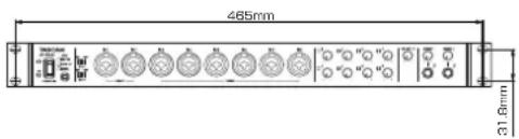
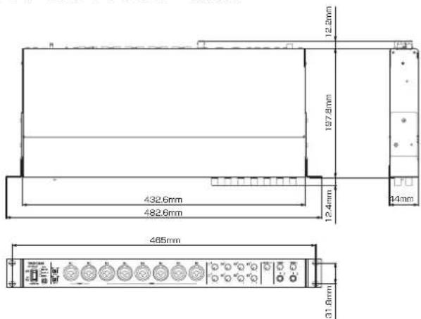
Dimensions
With standard frame attached
$$ 4 4 5 \times 5 9 \times 2 2 2 \mathrm{mm} (\mathrm{W} \times \mathrm{H} \times \mathrm{D}) $$
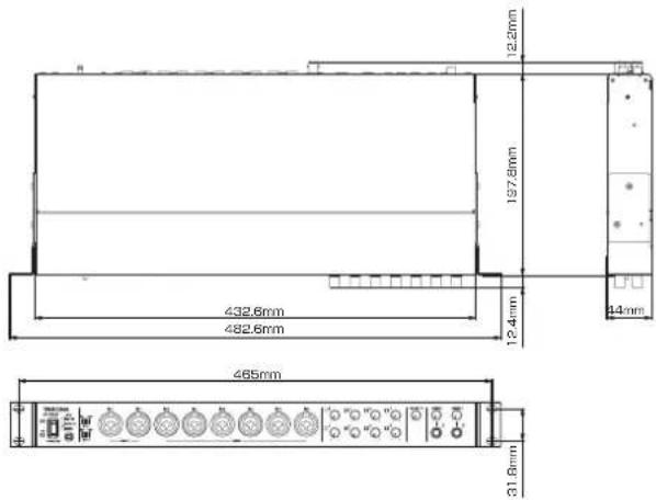
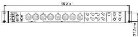
With rack mount adapters attached
$$ 4 8 2. 6 \times 4 4 \times 2 2 2. 4 \mathrm{mm} (\mathrm{W} \times \mathrm{H} \times \mathrm{D}) $$
■Weight
2.7 kg
Operating temperature range
5-35°C (32-104°F)
Dimensional drawings
■With standard frame attached (as shipped from the factory)

■With rack mount adapters attached
● Illustrations in this manual might differ in part from the actual product.
● Specifications and external appearance might be changed without notification to improve the product.
● Detailed specifications are provided in the Reference Manual.
PRÉCAUTIONS DE SÉCURITÉ IMPORTANTES
Pour le Canada
THIS CLASS B DIGITAL APPARATUS COMPLIES WITH CANADIAN ICES-003.
CET APPAREIL NUMÉRIQUE DE LA CLASSE B EST CONFORME À LA NORME NMB-003 DU CANADA.
DÉCLARATION DE CONFORMITÉ
⑫ Prise COAXIAL IN
natural_image
Diagram of a server rack with attached cable and connector pins (no text or symbols)ATTENTION
Options : S/PDIF, AES/EBU
flowchart
graph TD
    A["Analog Input"] --> B["Digital Input"]
    B --> C["Output Settings"]
    C --> D["Audio Filters"]
    D --> E["Channel Select"]
    E --> F["Output"]
    style A fill:#f9f,stroke:#333
    style B fill:#ccf,stroke:#333
    style C fill:#cfc,stroke:#333
    style D fill:#fcc,stroke:#333
    style E fill:#ffc,stroke:#333
    style F fill:#fcc,stroke:#333
    subgraph Channel Select
        G1["MIN OUT"] --> H1["MIN OUT"]
        H1 --> I1["MIN OUT"]
        I1 --> J1["MIN OUT"]
        J1 --> K1["MIN OUT"]
        K1 --> L1["MIN OUT"]
        L1 --> M1["MIN OUT"]
        M1 --> N1["MIN OUT"]
        N1 --> O1["MIN OUT"]
        O1 --> P1["MIN OUT"]
        P1 --> Q1["MIN OUT"]
        Q1 --> R1["MIN OUT"]
        R1 --> S1["MIN OUT"]
        S1 --> T1["MIN OUT"]
        T1 --> U1["MIN OUT"]
        U1 --> V1["MIN OUT"]
        V1 --> W1["MIN OUT"]
        W1 --> X1["MIN OUT"]
        X1 --> Y1["MIN OUT"]
        Y1 --> Z1["MIN OUT"]
    end
■OPTICAL (S/MUX) IN/OUT

Responsible: TEAC AMERICA, INC.
● Cable USB 2.0....×1
● Cable USB 3.0....×1
● Llave hexagonal....×1
① Interruptor y piloto STANDBY/ON
⑫ Toma COAXIAL IN
⑭ Conectores OPTICAL (S/MUX) IN/OUT
⑰ Conectores WORD IN/OUT
⑳ Conector DC IN 12V
natural_image
Technical line drawing of a rack-mounted device with attached cable (no text or symbols)CUIDADO
■OPTICAL (S/MUX) IN/OUT
Conectores: OPTICAL (JEITA RC-5720C)

⑭ OPTICAL (S/MUX) IN/OUT-Anschlüsse
⑰ WORD IN/OUT-Buchsen
natural_image
Pure mechanical assembly diagram showing a cable and clamping mechanism without any text or symbols■OPTICAL (S/MUX) IN/OUT

This equipment has been tested and found to comply with the limits for a Class B digital device, pursuant to Part 15 of the FCC Rules. These limits are designed to provide reasonable protection against harmful interference in a residential installation. This equipment generates, uses, and can radiate radio frequency energy and, if not installed and used in accordance with the instruction manual, may cause harmful interference to radio communications. However, there is no guarantee that interference will not occur in a particular installation. If this equipment does cause harmful interference to radio or television reception, which can be determined by turning the equipment off and on, the user is encouraged to try to correct the interference by one o più of the following measures.
a) Reorient or relocate the receiving antenna.
b) Increase the separation between the equipment and receiver.
c) Connect the equipment into an outlet on a circuit different from that to which the receiver is connected.
d) Consult the dealer or an experienced radio/TV technician for help.
CAUTION
Changes or modifications to this equipment not expressly approved by TEAC CORPORATION for compliance could void the user's authority to operate this equipment.
For Canada
THIS CLASS B DIGITAL APPARATUS COMPLIES WITH CANADIAN ICES-003.
CET APPAREIL NUMERIQUE DE LA CLASSE B EST CONFORME A LA NORME NMB-003 DU CANADA.
⑭ Connettori OPTICAL (S/MUX) IN/OUT
⑰ Connettori WORD IN/OUT
⑱ Interruttore 75Ω ON/OFF/THRU/WORD OUT
natural_image
Diagram of a server rack with attached cable and connectors (no text or symbols)CAUTELA
■OPTICAL (S/MUX) IN/OUT
Connettori: OPTICAL (JEITA RC-5720C)
Windows 8 (incluso 8.1) 32 bit
Windows 8 (incluso 8.1) 64 bit
Windows 7 32 bit SP1 o versioni successive
Windows 7 64 bit SP1 o versioni successive

natural_image
Line drawing of a server rack with attached cable and connectors (no text or symbols)注意
[Windows 版 Settings Panel《MIXER》タブ画面]
IEC60958-4 (AES/EBU)
- Settings Panelの《INTERFACE》タブ画面で切り換え
出力インピーダンス :75Ω
OPTICAL (S/MUX) IN / OUT
ラックマウントアダプター装着時
< In the United States >
This warranty gives you specific legal rights and you may also have other rights which vary from state to state. This warranty is only valid within the country the unit was originally purchased.
WHAT IS AND IS NOT COVERED
Except as specified below, this warranty covers all defects in materials and workmanship in this product. The following are not covered by the warranty:
- Damage to or deterioration of the external cabinet.
- Damages resulting from accident, misuse, abuse or neglect.
- Damage resulting from failure to perform basic daily maintenance and/or calibration or otherwise resulting from failure to follow instructions contained in your owner's manual.
- Damage occurring during shipment of the product. (Claims must be presented to the carrier)
- Damage resulting from repair or attempted repair by anyone other than TEAC or an authorized TASCAM service station.
- Damage resulting from causes other than product defects, including lack of technical skill, competence, or experience of the user.
- Damage to any unit which has been altered or on which the serial number has been defaced, modified or is missing.
WHO MAY ENFORCE THE WARRANTY
This warranty may be enforced only by the original purchaser.
LENGTH OF WARRANTY
All parts except heads and disk drives are warranted for one (1) year from the date of original purchase. Heads and disk drives are warranted to ninety (90) days from date of original purchase. Labor is warranted for ninety (90) days from date of original purchase.
WHAT WE WILL PAY FOR
We will pay all labor and material expenses for items covered by the warranty. Payment of shipping charges is discussed in the next section of this warranty.
HOW YOU CAN GET WARRANTY SERVICE
Your unit must be serviced by an authorized TASCAM service station in the United States. (This warranty is not enforceable outside the U.S.) If you are unable to locate an authorized TASCAM service station in your area, please contact us. We either will refer you to an authorized service station or instruct you to return the unit to the factory. Whenever warranty service is required, you must present a copy of the original dated sales receipt from an Authorized TASCAM Dealer.
You must pay any shipping charges if it is necessary to ship the product to service. However, if the necessary repairs are covered by the warranty, we will pay return surface shipping charges to any destination within the United States.
LIMITATION OF IMPLIED WARRANTIES
Any implied warranties, INCLUDING WARRANTIES OF MERCHANTABILITY AND FITNESS FOR A PARTICULAR PURPOSE, are limited in duration to the length of this warranty.
EXCLUSION OF DAMAGES
TEAC's liability for any defective product is limited to repair or replacement of the product, at TEAC's option. TEAC shall not be liable for:
-
Damages based upon inconvenience, loss of use of the product, loss of time interrupted operation or commercial loss; or
-
Any other damages, whether incidental, consequential or otherwise.
Some states do not allow limitations on how long an implied warranty lasts and/or do not allow the exclusion or limitation of incidental or consequential damages, so the above limitations and exclusions may not apply to you.
To locate an Authorized Service Center in Your Area
CALL 1-800-447-8322
This product is subject to the legal warranty regulations of the country of purchase. In case of a defect or a problem, please contact the dealer where you bought the product.
These warranty provisions in Japanese are valid only in Japan.
< In other countries/areas >
This warranty gives you specific legal rights, and you may also have other rights that vary by country, state or province.
If you have a warranty claim or request, please contact the dealer where you bought the product.
If you require repair services for your TASCAM equipment, please contact the dealer where the product was purchased from or the TASCAM Distributor in your country. A list of TASCAM Distributors can be found on our website at: http://teac-global.com/
WARRANTY / 保証書
Model/型名
Owner's name / お名前
US-20x20
Serial No.

- USB Audio MIDI Interface with Mic Pre/Mixer
- ティアック株式会社
- Owner's Manual
- IMPORTANT SAFETY PRECAUTIONS
- For U.S.A.
- INFORMATION TO THE USER
- CAUTION
- For Canada
- DECLARATION OF CONFORMITY
- IMPORTANT SAFETY INSTRUCTIONS
- ■or European Customers
- Disposal of electrical and electronic equipment
- Contents
- Introduction
- Note about the Reference Manual
- Included items
- NOTE
- Precautions for placement and use
- Using the TEAC Global Site
- Beware of condensation
- Cleaning the unit
- User registration
- MIC PRE
- AUDIO I/F
- MIXER
- Rear panel
- ⑫ COAXIAL IN jack
- ⑬ USB port
- ⑭ OPTICAL (S/MUX) IN/OUT connectors
- ⑮ MIDI OUT jack
- ⑯ MIDI IN jack
- ⑰ WORD IN/OUT connectors
- ⑱ 75Ω ON/OFF/THRU/WORD OUT switch
- ⑲ LINE IN 9-10 (BALANCED) jacks and LEVEL switch
- ⑳ COAXIAL OUT jack
- ②1 LINE OUT (BALANCED) 1–10 jacks
- ② AUTO POWER SAVE switch
- ②3 Cord holder
- ⑳ DC IN 12V connector
- Installing the dedicated software
- Installing the Windows driver
- ■Windows driver installation procedures
- Installing the Mac Settings Panel
- ■Mac Settings Panel installation procedures
- Connecting the power
- Changing the outlet plug
- Connecting with a computer
- Making computer settings
- Making settings on the MIXER screen
- Windows
- Mac OS X
- ① EQUALIZER
- ② COMPRESSOR
- ③ Mode
- ④ REVERB
- ⑤ Select buttons
- ⑥ PHASE buttons
- ⑦ EQ buttons
- ⑧ COMP buttons
- ⑨ Effect AUX selection buttons
- ⑩ AUX 1–4 knobs and indicators
- ⑪ SOLO buttons
- ⑫ MUTE buttons
- ⑬ Pan sliders
- ■etting the sample clock source
- ■etting the sampling frequency used when set to INTERNAL
- ■etting the digital output format
- ■etting the digital input destination (only when 176.4kHz/192kHz)
- Making settings on the OUTPUT SETTING screen
- Examples of connections with other equipment
- Connecting with iOS devices
- Adjusting the input sound
- Overview of operation modes
- Using the unit as a microphone preamp
- Using the unit as an audio interface
- Using the unit as a digital mixer
- Changing sampling frequency
- ■h mic preamp and digital mixer modes
- Mac
- ■ in audio interface mode
- Input and output channels in mic preamp mode
- Input/output channels at 44.1/48kHz sampling frequency
- Troubleshooting
- Operating environment
- ■he dedicated software cannot be installed
- ■he unit is connected, but the computer does not recognize it.
- ■here is no sound even when audio is playing back on the computer.
- Windows 8/Windows 7
- ■ound breaks up or there is noise.
- Specifications
- Ratings
- Analog inputs
- Analog outputs
- Digital audio input/output ratings
- Control input/output ratings
- Audio performance
- Computer system requirements
- OS devices
- Supported audio drivers
- General
- Power
- Power consumption
- Dimensions
- ■Weight
- Operating temperature range
- Dimensional drawings
- PRÉCAUTIONS DE SÉCURITÉ IMPORTANTES
- Pour le Canada
- DÉCLARATION DE CONFORMITÉ
- ⑫ Prise COAXIAL IN
- ATTENTION
- ■OPTICAL (S/MUX) IN/OUT
- ⑫ Toma COAXIAL IN
- ⑭ Conectores OPTICAL (S/MUX) IN/OUT
- ⑰ Conectores WORD IN/OUT
- ⑳ Conector DC IN 12V
- Apply or install
- CUIDADO
- ⑭ OPTICAL (S/MUX) IN/OUT-Anschlüsse
- ⑰ WORD IN/OUT-Buchsen
- ⑭ Connettori OPTICAL (S/MUX) IN/OUT
- ⑰ Connettori WORD IN/OUT
- ⑱ Interruttore 75Ω ON/OFF/THRU/WORD OUT
- CAUTELA
- 注意
- OPTICAL (S/MUX) IN / OUT
- < In the United States >
- WHAT IS AND IS NOT COVERED
- WHO MAY ENFORCE THE WARRANTY
- LENGTH OF WARRANTY
- WHAT WE WILL PAY FOR
- HOW YOU CAN GET WARRANTY SERVICE
- LIMITATION OF IMPLIED WARRANTIES
- EXCLUSION OF DAMAGES
- To locate an Authorized Service Center in Your Area
- < In other countries/areas >
Brand : TASCAM
Model : US-20x20
Category : Hi-Fi System