
ACO D205 - Freezer WHIRLPOOL - Free user manual and instructions
Find the device manual for free ACO D205 WHIRLPOOL in PDF.

| Product type | Professional freezer (blast chiller) |
| Model | ACO D205 (multiple capacity range) |
| Cooling capacity (positive) | 8 kg (3x1/1 GN) / 12 kg (5x1/1 GN+60x40) / 25 kg (10x1/1 GN+60x40) |
| Cooling capacity (negative) | 5 kg (3x1/1 GN) / 8 kg (5x1/1 GN+60x40) / 15 kg (10x1/1 GN+60x40) |
| Number of GN pans | 3 x 1/1 GN or 5 x 1/1 GN+60x40 or 10 x 1/1 GN+60x40 |
| Power supply | 230 V ~ 50 Hz (single phase) |
| Refrigerant gas | R452A |
| Cooling power | 0.46 kW (3x1/1 GN) / 0.65 kW (5x1/1) / 1.17 kW (10x1/1) |
| Total power consumption | 0.5 kW (3x1/1) / 0.65 kW (5x1/1) / 1.21 kW (10x1/1) |
| Gross volume | 0.37 m³ (3x1/1) / 0.68 m³ (5x1/1) / 1.19 m³ (10x1/1) |
| Gross weight | 64 kg (3x1/1) / 86 kg (5x1/1) / 118 kg (10x1/1) |
| Control panel | Electronic with digital display and LED |
| Main functions | Quick cooling, hard quick cooling, blast freezing, soft blast freezing, pre-cooling, storage |
| Automatic cycles | Phase sequencing: cooling then storage |
| Core probe | Integrated, automatic insertion test, cleaning recommended after each use |
| Alarms | Door open (id), cycle not finished (tiME), high pressure (HP), condenser overheat (COH), compressor blocked (CSd) |
| Safety | Keypad lock/unlock (Loc/UnL), emergency stop via start/stop button |
| Cleaning and maintenance | Clean interior with soapy water; brush or vacuum condenser monthly; clean core probe after use |
| Spare parts and repairability | Original spare parts available from authorized technical service |
| Installation | Minimum distance from walls, ventilation, leveling with adjustable feet |
| Disposal | Compliant with WEEE 2012/19/EU: do not dispose of with household waste |
Frequently Asked Questions - ACO D205 WHIRLPOOL
User questions about ACO D205 WHIRLPOOL
0 question about this device. Answer the ones you know or ask your own.
Ask a new question about this device
Download the instructions for your Freezer in PDF format for free! Find your manual ACO D205 - WHIRLPOOL and take your electronic device back in hand. On this page are published all the documents necessary for the use of your device. ACO D205 by WHIRLPOOL.
USER MANUAL ACO D205 WHIRLPOOL
natural_image
Simple line drawing of an open book with no text or symbols on the pages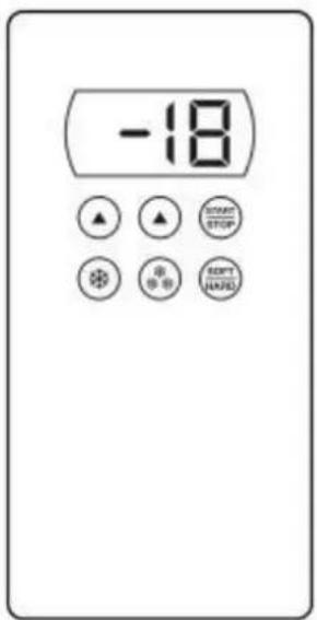
| ACO D 103 | |
| ACO D 205 | |
| ACO D 210 | |
| Dimensioni | Capacità | Distanza teglie | Peso a vuoto |
| Dimensions | Capacity | Trays distance | Empty weight |
| Abmessungen | Kapazität | Einschubabstand | Leergewicht |
| Dimensions | Capacité | Ecartement grilles | Poids à vide |
| Dimensiones | Capacidad | Distancia bandejas | Peso en vacío |
| Afmetingen | Capaciteit | Afstand dienbladen | Leeggewicht |
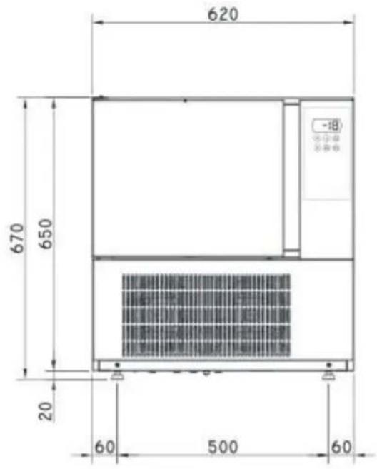
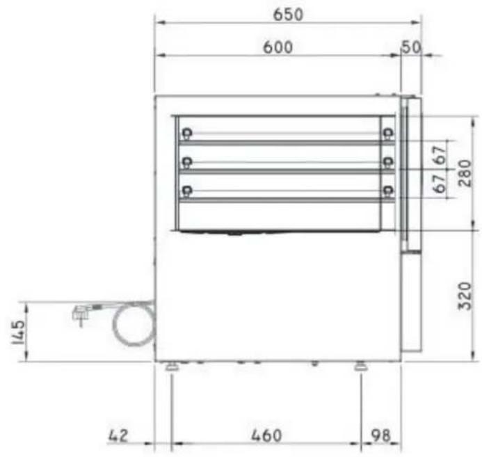
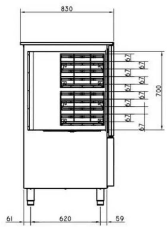
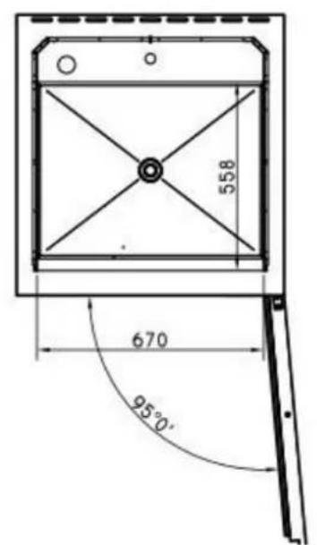
| mm 620 x 650 x h 670 | 3 x 1/1 GN | 67 mm | 54 kg |
| Dimensioni | Capacità | Distanza teglie | Peso a vuoto |
| Dimensions | Capacity | Trays distance | Empty weight |
| Abmessungen | Kapazität | Einschubabstand | Leergewicht |
| Dimensions | Capacité | Ecartement grilles | Poids à vide |
| Dimensiones | Capacidad | Distancia bandejas | Peso en vacío |
| Afmetingen | Capaciteit | Afstand dienbladen | Leeggewicht |
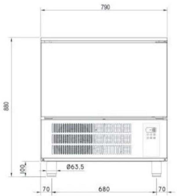
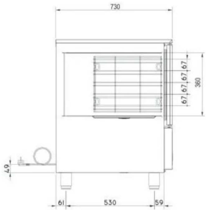
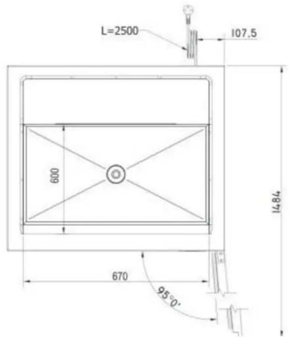
| mm 790 x 730 x h 880 | 5 x 1/1 GN - 60x40 | 67 mm | 74 kg |
| Dimensioni | Capacità | Distanza teglie | Peso a vuoto |
| Dimensions | Capacity | Trays distance | Empty weight |
| Abmessungen | Kapazität | Einschubabstand | Leergewicht |
| Dimensions | Capacité | Ecartement grilles | Poids à vide |
| Dimensiones | Capacidad | Distancia bandejas | Peso en vacío |
| Afmetingen | Capaciteit | Afstand dienbladen | Leeggewicht |
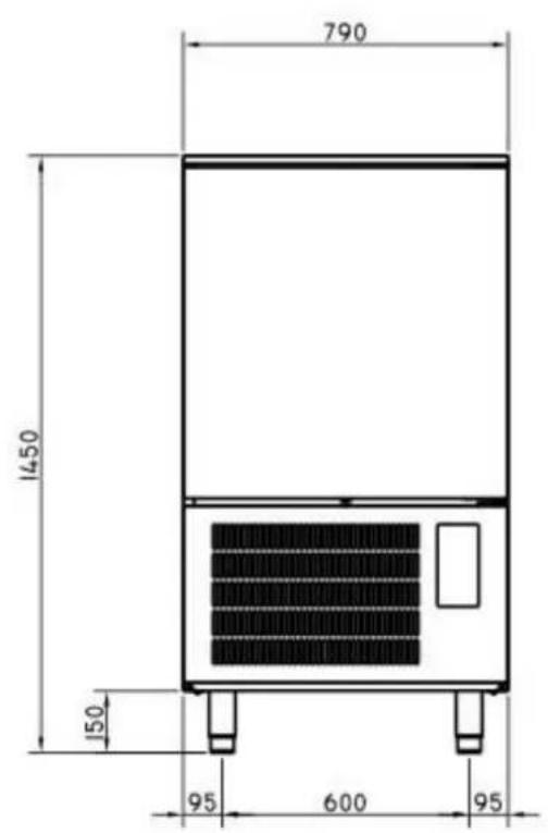
| mm 790 x 830 x h 1450 | 10 x 1/1 GN | 67 mm | 118 kg |
natural_image
Illustration of a pallet jack lifting a large box (no text or symbols)
natural_image
Isometric illustration of a server unit with a red upward arrow inside, labeled 'B' (no text or symbols on the device itself)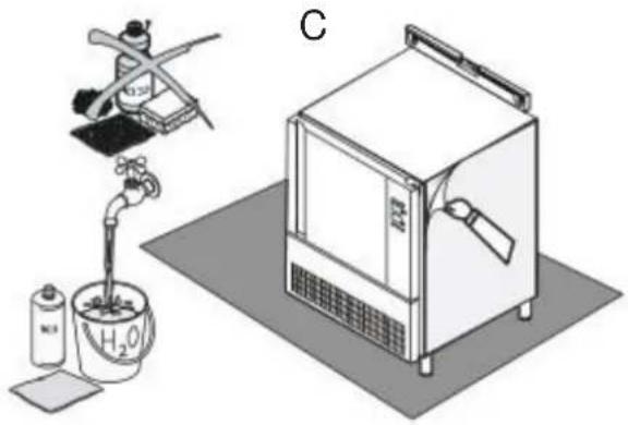
natural_image
Illustration of a laboratory setup with a gas collection bottle, a water tap, and a control unit (no text or symbols visible)3.3. SMALTIMENTO DELL'IMBALLO
natural_image
Isometric line drawing of a microwave oven with a downward arrow indicating airflow or cooling (no text or symbols)IL COSTRUTTORE DECLINA OGNI RESPONSABILITÀ' PER EVENTUALI DANNI CAUSATI DALLA MANCANZA DI MESSA A TERRA DELL'IMPIANTO.
| Paragraph | Page | |
| Foreword | 15 | |
| Declaration of conformity | 15 | |
| European directive ROHS 2012/19/UE | 15 | |
| 1. | Warnings | 15 |
| 1.1 | General warnings | 15 |
| 1.2 | Technical warnings | 15 |
| 1.3 | Use warnings | 15 |
| 2. | General technical features | 16 |
| 2.1 | Data sheet | 16 |
| 3. | Instructions for the installer | 16 |
| 3.1 | Controls at reception | 16 |
| 3.2 | Handling and placing | 16 |
| 3.3 | Unpacking and disposal of it | 17 |
| 3.4 | Disposal of unit | 17 |
| 4. | Start-up | 17 |
| 5. | Control panel | 18 |
| 5.1 | Description of the led in the lower side of the display | 18 |
| 6. | Operation | 18 |
| 6.1 | Switching the device on/off | 18 |
| 6.2 | Locking/unlocking the keyboard | 18 |
| 6.3 | Operating cycles | 18 |
| 6.3A | Blast chilling and conservation | 19 |
| 6.3B | Hard blast chilling and conservation | 19 |
| 6.3C | Deep freezing and conservation | 19 |
| 6.3D | Soft deep freezing and conservation | 20 |
| 6.3E | Pre-cooling | 20 |
| 7. | Alarms and errors | 21 |
| 7.1 | Alarms | 21 |
| 7.2 | Errors | 21 |
| 8. | Cleaning and maintenance | 21 |
FOREWORD
The contents of this manual are generic and not all the functions described may be available on your product.
The manufacturer declines all responsibility for possible inaccuracies contained in this pamphlet, due to printing or copy errors. We reserve the right to make on our own products those changes to be considered necessary or useful, without jeopardizing the essential characteristics.
Read the instructions for use very carefully paying particular attention to the rules concerning safety devices.
This appliance must only be used for what it has been designed for and built for.
DECLARATION OF CONFORMITY
The Manufacturer declares that the appliances conform to the EEC norms.
They must be installed in accordance with current standards, especially regarding aeration of the premises and the exhaust gas evacuation system.
Note: The Manufacturer declines all and every responsibility for any direct damages caused by: an incorrect use, wrong installation or bad maintenance.
EUROPEAN DIRECTIVE ROHS 2012/19/UE
This appliance is marked according to the European directive 2012/19/UE on Waste Electrical and Electronic Equipment (WEEE).
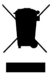
By ensuring this product is disposed correctly, you will help prevent potential negative consequences for the environment and human health, which could otherwise be caused by inappropriate waste handling of this product.
The symbol on the product, or on the documents accompanying the product, indicates that this appliance may not be treated as household waste.
Instead it shall be handed over to the applicable collection point for the recycling of electrical and electronic equipment.
Disposal must be carried out in accordance with local environmental regulations for waste disposal.
1. WARNINGS
1.1. GENERAL WARNINGS
This manual has been prepared to enable a correct installation, regulation and maintenance of the appliance. It is therefore of basic importance that the warnings contained in this booklet are carefully read as they supply essential indications regarding the safety of the installation, use and maintenance.
This manual and the wiring diagram must be stored with care and made available to the operator for any future consultation. The appliance must be installed, tested and serviced by qualified personnel in possession of the legal qualifications. The constructor declines all responsibility with invalidity of the warranty in the event of electrical and/or mechanical modifications.
Any adjustment whatsoever not expressly authorised and in disrespect of this manual invalidate the warranty. Observe all existing local regulations at the time of installation. Check that the characteristics of the electric grid correspond to the data given on the serial plate of the appliance. The packing materials (plastic bags, polystyrene, nails, etc.) as potential hazards, must be kept out of the reach of children and properly recycled according to the existing local regulations.
The appliance has been designed and constructed for the blast chilling and freezing of foodstuffs and should therefore be destined to this sole purpose for which it has been expressly conceived. Any use besides this specific purpose does not commit the constructor in any way. Shutdown the appliance in the event of breakdown or malfunctions. For eventual repairs contact exclusively the authorised service centres and request the use of original spare parts. If in doubt do not use the appliance and contact professionally qualified personnel. The disrespect of the above conditions could risk the safety of the appliance.
1.2. TECHNICAL WARNINGS
The appliance must be used by qualified personnel. Keep off the children from the appliance above all if it is in function. Every appliance has a serial plate on the right side.
1.3. USE WARNINGS
Remove from the room any stranger material as manual, plastic bags, polystyrene, nails, etc before start operating with the equipment. Clean the inside and outside surfaces only with warm water and soap or a neutral detergent. Rinse with plenty of water and dry thoroughly.
Don't use abrasive brushes or other damaging materials for the appliance's surfaces.
At the end of the working day, clean the inside (above all) and outside of the machine, to ensure smooth operation of the appliance and prolong its useful life. Do not use high pressure water jets when cleaning the appliance.
Never stretch the power cable. Place the machine in a ventilated room. When using the appliance, never obstruct the air inlet when the appliance in on, so as not to compromise its performance and safety.
For the final disposal of this appliance, comply with local regulations in force.
2. GENERAL TECHNICAL FEATURES
2.1. DATA SHEET
| Model | Cooling capacity | Voltage | Gas | Cooling pow. | Tot. pow. | Packed vol. | Gross Weight |
| 3 x 1/1GN | 8 Kg (+3 °C)5 Kg (-18 °C) | 230 V1N 50 Hz | R452A | 0.46 Kw | 0.5 Kw | 0.37 m3 | 64 kg |
| 5 x 1/1 GN+ 60x40 | 12 Kg (+3 °C)8 Kg (-18 °C) | 230 V1N 50 Hz | R452A | 0.65 Kw | 0.65 Kw | 0.68 m3 | 86 kg |
| 10 x 1/1 GN+ 60x40 | 25 Kg (+3 °C)15 Kg (-18 °C) | 230 V1N 50 Hz | R452A | 1.17 kW | 1.21 kW | 1.19 m3 | 118 kg |
3. INSTRUCTIONS FOR THE INSTALLER
Read carefully all the instructions in this manual, because they give important suggestions about the right installation and use of the appliance.
3.1. CONTROLS AT RECEPTION
The appliance are shipped in appropriate protective packing.
On arrival, check that the appliance has not incurred in transport damage and that it is complete according to the order.
In the event of visible damage immediately note the damage on the transport documents with the following wording: "RECEIVED WITH RESERVE FOR EVIDENT DAMAGE OF PACKING".
3.2. HANDLING AND PLACING
IMPORTANT: All the operations indicated below must be performed in respect of the existing safety regulations, both for the equipment in use and for the operating procedures.
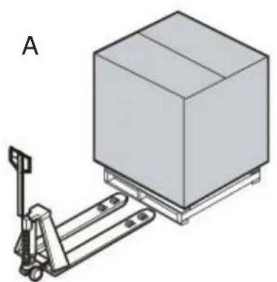
ATTENTION: Before beginning handling operations ensure that the lifting capacity is enough for the appliance in question.
Handling with fork lift or similar (A); Insert the forks into the side or back of the wooden pallet supplied with the appliance, begin lifting checking that the appliance is in stable equilibrium.
When insert the lifting device, pay attention to the power supply cable and the position of the feet.
ATTENTION: during handling do not tip or turn over.
WARNING: the respect of the recommendations printed on the outside of the packing is a guarantee of a sound physical and operating condition of the appliance, all to the advantage of the end-user.
THEREFORE THE FOLLOWING IS RECOMMENDED:
- HANDLE WITH CARE
- KEEP DRY
- STACKING OF OTHER OBJECTS ON THE APPLIANCE MUST BE ABSOLUTELY AVOIDED
• DO NOT COMPRESS SIDEWAYS
• DO NOT TURN UPSIDE DOWN - STACKING OF BLAST CHILLERS IS PERMITTED: READ CAREFULLY THE MAXIMUM PIECES' NUMBER INDICATED ON THE EMBALLAGE.
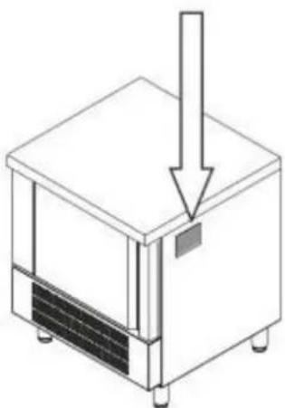
Lift the appliance to separate it from the pallet.
Remove the packing (B) and the protective film avoid using abrasive brushes or other damaging materials for the appliance's surfaces (C).
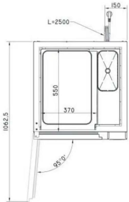
Check that the appliance is perfectly levelled.
Regulate the adjustable feet if necessary. Place the appliance away from heat sources and in a ventilated room.
When using the appliance, never obstruct the air inlet when the appliance in on, so as not to compromise its performance and safety.
Placing the appliance in a site easy to join, so every type of maintenance, control and repair may be done easily.
natural_image
Illustration of a pallet jack lifting a large box (no text or symbols)
natural_image
Isometric illustration of a refrigerated industrial machine with a red upward arrow inside, labeled 'B' (no text or symbols on the device itself)
natural_image
Illustration of a laboratory setup with a gas collection bottle, a hand pump, and a control unit (no text or symbols visible)3.3. UNPACKING AND DISPOSAL OF IT
Place the appliance on the ground in its chosen position.
Check that the serial number corresponds to the transport documents. Check for visible damages.
Keep the packing out of the reach of children, as it could be a danger hazard. Discharge the packing products to the specialised collection or recycling points in respect of the existing regulations.
3.4. DISPOSAL OF UNIT
Before scrapping the appliance, keep it inoperative by removing the power cable, eliminating all parts of the appliance that could constitute an hazard and invalidate locks, hinges and any other closing devices to avoid that children playing could be trapped inside or injured.
IMPORTANT: COMPLY WITH LOCAL REGULATIONS IN FORCE CONCERNING THE FINAL DISPOSAL OF THIS TYPE OF EQUIPMENT
4. START-UP
Before connecting the appliance check that the data on the serial plate correspond to the actual electrical supply.
The serial plate giving the electrical data required in the installation is placed in the right side.
The installation must be made according to the instructions given in this section, by professionally qualified personnel.
THE ELECTRICAL SAFETY OF THIS APPLIANCE IS GUARANTEED ONLY WHEN IT IS CONNECTED TO AN EFFICIENT EARTHING PLANT AS PRESCRIBED BY EXISTING ELECTRICAL SAFETY REGULATIONS.
THIS BASIC SAFETY REQUIREMENT MUST BE VERIFIED AND, IF IN DOUBT, REQUEST A CAREFUL CONTROL OF THE PLANT BY PROFESSIONALLY QUALIFIED PERSONNEL.
natural_image
Isometric line drawing of a microwave oven with a downward arrow indicating airflow or cooling (no text or symbols)THE CONSTRUCTOR DECLINES ALL RESPONSIBILITY FOR DAMAGES CAUSED BY THE DISRESPECT OF AN EFFICIENT EARTHING OF THE PLANT.
Check that the appliance is perfectly levelled.
Regulate the adjustable feet if necessary.
Check that the plastic protective coating is removed from all external surfaces.
Check that the interior is washed with warm water and a neutral soap.
Check that the appliance is positioned as far as possible from heat sources.
Check that the free air circulation around the motor compartment is not obstructed.
Control the voltage and frequency of the mains distribution, they must fall within the given values: 230 V ± 10%; 50 Hz / 400 V ± 10%; 50 Hz
5. CONTROL PANEL
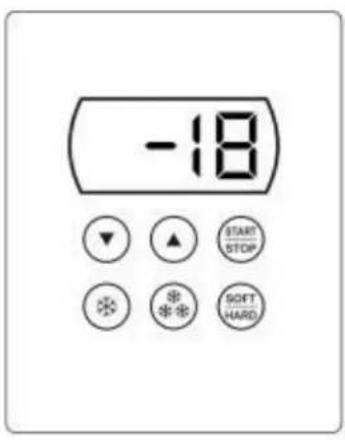
Start/stop (on/off) key

Increase value key

Decrease value key
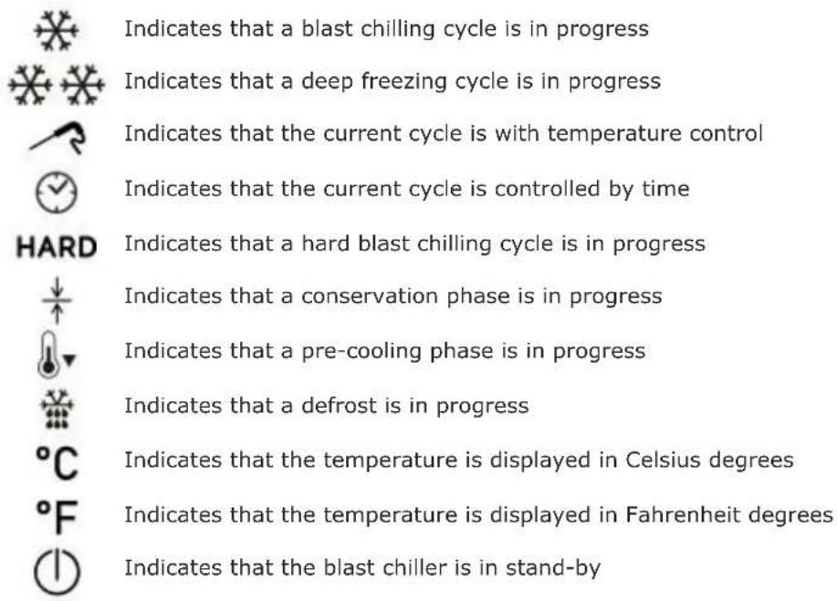
5.1 DESCRIPTION OF THE LED IN THE LOWER SIDE OF THE DISPLAY
In the lower part of the display there are LEDs that provide important information about the operating mode.
6. OPERATION
6.1 SWITCHING THE DEVICE ON/OFF
Operate as follows: hold the START/STOP key down for 1 s.
When the blast chiller is on, the display shows the temperature inside the cell.
6.2 LOCKING/UNLOCKING THE KEYBOARD
To lock or unlock the keyboard operate as follows:
To lock: hold the down key and the start/stop key down for 1 s: the display will show Loc for 1 s. When the keyboard is locked, no operation is allowed.
To unlock: hold the down key and the start/stop key down for 1 s: the display will show UnL for 1 s.
The devices can manage the following operating cycles:
- Blast chilling and conservation
• Hard blast chilling and conservation - Deep freezing and conservation
- Soft deep freezing and conservation.
6.3A BLAST CHILLING AND CONSERVATION
The temperature-controlled blast chilling and conservation cycle is divided into the following two phases:
- Blast chilling
- Conservation
On conclusion of a phase, the device passes automatically to the next.
Operate as indicated to start the cycle:
- Press and release the blast chilling key: the blast chilling LED and the core probe LED will flash.
- Press start, when the sensor measures a temperature identical to the camera (sound signal and the probe flashes), it automatically switches to time.
- Selecting the temperature control, the display will show the temperature that the probe will detect at the end of blast chilling.
- By selecting the time control, the display will show the duration of the cycle.
- After selecting the type of blast chilling (temperature or time control) it is possible to modify the end cycle value by pressing (within 15 seconds) the key increase or the key decrease until reaching the chosen value.
- At this point, to start the cycle press and release the start/stop key.
- If the temperature control has been selected, the system starts a test to verify the correct insertion of the probe. If the test is successfully completed the cooling cycle will start; otherwise a time-controlled cooling cycle will be started (in this case, the probe led turns off and the time led lights up).
- To stop the cooling cycle, keep pressed the start/stop key.
- During temperature-controlled chilling, the cell temperature can be displayed by pressing the blast chilling key. After 15 seconds, the display returns to displaying the temperature detected by the probe.
- If the temperature detected by the probe reaches the blast chilling end value within the maximum expected duration, the cycle will be considered correct and the blast chiller will automatically go to the conservation phase.
- When switching from blast chilling to conservation phase, the buzzer is activated for a set time. - During storage, the display shows the temperature detected by the probe and the LED conservation lights up in the lower part of the display.
- If the temperature detected by the probe does not reach the blast chilling end value within the maximum expected duration, blast chilling will not be completed correctly but will continue.
- The probe LED will flash and the buzzer will be activated.
6.3B HARD BLAST CHILLING AND CONSERVATION
The temperature-controlled hard blast chilling and conservation cycle is divided into the following three phases:
- blast chilling hard phase
- blast chilling
- conservation
On conclusion of a phase, the device passes automatically to the next.
Operate as indicated to start the cycle:
- Press and release the blast chilling key: the blast chilling LED and the core probe LED will flash.
- Press and release the hard/soft key (the hard LED will flash).
- At this point, to start the cycle press and release the start/stop key.
6.3C DEEP FREEZING AND CONSERVATION
The temperature-controlled deep freezing and conservation cycle is divided into the following two phases:
- Deep freezing
- Conservation
On conclusion of a phase, the device passes automatically to the next.
Operate as indicated to start the cycle:
- Press and release the deep freezing key (the LED blast chilling, deep freezing, hard and probe will flash).
- Pressing again the deep freezing key the system passes from the temperature control to the time control (in this case, the probe led turns off and the time led lights up).
- At this point, to start the cycle press and release the start/stop key.
- The system starts a test to verify the correct insertion of the probe. If the test is successfully completed the cooling cycle will start.
6.3D SOFT DEEP FREEZING AND CONSERVATION
The soft deep freezing and conservation cycle is divided into the following two phases:
- Deep freezing soft phase
- Deep freezing
- Conservation
On conclusion of a phase, the device passes automatically to the next.
Operate as indicated to start the cycle:
- Press and release the deep freezing key (the LED blast chilling, deep freezing, hard and probe will flash).
- Press and release the hard/soft key (the hard led turns off).
- At this point, to start the cycle press and release the start/stop key.
- The system starts a test to verify the correct insertion of the probe. If the test is successfully completed the cooling cycle will start.
6.3E PRE-COOLING
Each cooling cycle can be preceded by a precooling phase.
Operate as indicated to start pre-cooling:
- Hold the blast chilling key down for 1 second: (the pre-cooling LED will flash).
- The pre-cooling phase will start and continue until the temperature for pre-cooling is reached.
- When the cell reaches the expected temperature, the pre-cooling led stops flashing and remains fixed.
- The buzzer is activated for one second.
- Pre-cooling continues until a cycle is started. To
stop pre-cooling:
- Hold the blast chilling key down for 1 second or start a cycle.
7. ALARMS AND ERRORS
7.1 ALARMS
The following table illustrates the meaning of the alarm codes:
| Code | Description | Causes | Reset |
| tiME | Temperature chilling or freezing cycle not completed within the maximum expected duration. | Automatic | |
| id | Open door | Inefficient door closure.Possible breakage of the micro door or magnetic sensor. | Automatic |
| HP | High pressure | Probable excessive amount of product per tray. | Automatic |
| COH | Condenser overheated | Contact Technical Service | |
| CSd | Compressor blocked | Contact Technical Service |
7.2 ERRORS
The following table illustrates the meaning of the error codes:
| Code | Description | Causes and solutions | Reset |
| Pr1 | Cell probe error | Probe disconnected or broken.Check probe integrity.Check probe-device connection.Replace the probe. | Automatic |
| Pr2 | Core probe error | Probe disconnected or broken.Check probe integrity.Check probe-device connection.Replace the probe. | Automatic |
| Pr3 | Evaporator probe error | Contact Technical Service | |
| Pr4 | Condenser probe error | Contact Technical Service |
8. CLEANING AND MAINTENANCE
This section has been dedicated to the end-user and is extremely important for the appliance to work correctly in the long-term. A few simple operations conscientiously carried out at set periods can avoid the need of servicing by specialised personnel. The operations to be made do not require any particular technical knowledge and can be summarised in simple controls of the appliance components.
BEFORE BEGINNING ANY TYPE OF MAINTENANCE OR CLEANING WORK ON THE APPLIANCE DISCON-NECT THE MAINS POWER SUPPLY.DO NOT WASH THE APPLIANCE DIRECTLY WITH HIGH PRESSURE WATER JETS.AVOID SPRAYING WATER DIRECTLY ONTO ELECTRICAL PARTS.
APPLIANCE Check that the bodywork is clean. Pay particular attention to the sections in steel. Clean the inside and outside surfaces only with warm water and soap or a neutral detergent. Rinse with plenty of water and dry thoroughly. If the appliance is inactive for long periods of time proceed as follows: turn the main switch to the OFF position. Remove the plug from its socket. Empty the appliance and clean. Leave the door half-open to avoid creation of bad smells. Protect the compressor group from dust.
CORE PROBE Clean well the edge for the first use of it, and after every use. If it's not in use, after cleaning, cover with its rubber cap and place it in the proper side, within the appliance's chamber.
CONDENSING COIL It is important that the coil is capable of offering the maximum possible heat exchange. It is therefore important that its surface be always free of dirt or dust that may be deposited by the effect of the fan's operation. Use a vacuum cleaner and soft bristled brush to remove all the impurities such as paper or dust that may have deposited on the coil. Check that the aluminium fins have not been damaged or bent; if this is the case "comb" the coil with the appropriate tool until the original condition is regained to optimise the air flux.
POWER CABLE Check that the power cable that connects the appliance to the mains socket is not cut, cracked or altered in such a way as to compromise the insulation.
Contact your authorised service centre if this requires maintenance.
natural_image
Illustration of a pallet jack lifting a rectangular box (no text or symbols)
natural_image
Isometric illustration of a server unit with a red upward arrow inside, labeled 'B' (no text or symbols on the device itself)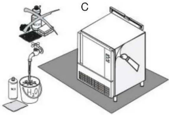
natural_image
Illustration of a laboratory setup with a gas collection bottle, a hand pump, and a control unit (no text or symbols visible)natural_image
Isometric line drawing of a microwave oven with a vertical arrow indicating airflow or cooling (no text or symbols)DÉCLARATION DE CONFORMITÉ
natural_image
Silhouette of a trash bin with crossed lines and a solid rectangle below (no text or symbols)natural_image
Illustration of a pallet jack lifting a rectangular box (no text or symbols)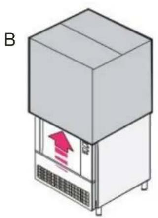
natural_image
Illustration of a refrigerated industrial machine with a red upward arrow inside, labeled 'B' (no text or symbols on the device itself)
natural_image
Illustration of a laboratory setup with a pipette, a water bath, and a gas collection unit (no text or symbols)3.3. ÉLIMINATION DE L'EMBALLAGE
natural_image
Isometric line drawing of a microwave oven with a downward arrow indicating airflow or cooling (no text or symbols)LE FABRICANT DÉCLINE TOUTE RESPONSABILITÉ POUR D'ÉVENTUELS DOMMAGES PROVOQUÉES PAR L'ABSENCE DE MISE À TERRE DE L'INSTALLATION.
- surgélation
- conservation
- phase soft de surgélation
- surgélation
- conservation
natural_image
Silhouette of a trash bin with crossed lines and a solid rectangle below (no text or symbols)natural_image
Illustration of a pallet jack lifting a rectangular box (no text or symbols)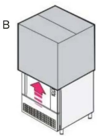
natural_image
Isometric illustration of a server unit with a red upward arrow inside, labeled 'B' (no text or symbols on the device itself)
natural_image
Illustration of a laboratory setup with a gas collection bottle, a water tap, and a control unit (no text or symbols visible)natural_image
Isometric line drawing of a microwave oven with a downward arrow indicating airflow or cooling (no text or symbols)1.1. ALGEMENE WAARSCHUWINGEN
3.2. VERPLAATSING EN PLAATSING
natural_image
Illustration of a pallet jack lifting a rectangular box (no text or symbols)
natural_image
Illustration of a refrigerated industrial machine with a red upward arrow inside, labeled 'B' (no text or symbols on the device itself)
natural_image
Illustration of a laboratory setup with a pipette, a water bath, and a gas collection unit (no text or symbols)natural_image
Isometric line drawing of a microwave oven with a downward arrow indicating airflow or cooling (no text or symbols)DE FABRIKANT KAN NIET AANSPRAKELIJK WORDEN GESTELD VOOR SCHADE ALS DE INSTALLATIE NIET OP AFDOENDE WIJZE WORDT GEAARD.
Start-/stoptoets (on/off)

6.3A SNELKOELING EN CONSERVATIE
6.3B HARD SNELKOELING EN CONSERVATIE

- SMALTIMENTO DELL'IMBALLO
- FOREWORD
- DECLARATION OF CONFORMITY
- EUROPEAN DIRECTIVE ROHS 2012/19/UE
- WARNINGS
- GENERAL WARNINGS
- TECHNICAL WARNINGS
- USE WARNINGS
- GENERAL TECHNICAL FEATURES
- DATA SHEET
- INSTRUCTIONS FOR THE INSTALLER
- CONTROLS AT RECEPTION
- HANDLING AND PLACING
- THEREFORE THE FOLLOWING IS RECOMMENDED:
- UNPACKING AND DISPOSAL OF IT
- DISPOSAL OF UNIT
- START-UP
- CONTROL PANEL
- DESCRIPTION OF THE LED IN THE LOWER SIDE OF THE DISPLAY
- OPERATION
- SWITCHING THE DEVICE ON/OFF
- LOCKING/UNLOCKING THE KEYBOARD
- 6.3A BLAST CHILLING AND CONSERVATION
- 6.3B HARD BLAST CHILLING AND CONSERVATION
- 6.3C DEEP FREEZING AND CONSERVATION
- 6.3D SOFT DEEP FREEZING AND CONSERVATION
- 6.3E PRE-COOLING
- ALARMS AND ERRORS
- ALARMS
- ERRORS
- CLEANING AND MAINTENANCE
- DÉCLARATION DE CONFORMITÉ
- ÉLIMINATION DE L'EMBALLAGE
- ALGEMENE WAARSCHUWINGEN
- VERPLAATSING EN PLAATSING
- 6.3A SNELKOELING EN CONSERVATIE
- 6.3B HARD SNELKOELING EN CONSERVATIE
Brand : WHIRLPOOL
Model : ACO D205
Category : Freezer