
MUL-650 - Multimeter Steren - Free user manual and instructions
Find the device manual for free MUL-650 Steren in PDF.


| Product Type | Bluetooth Professional Multimeter |
| Brand | Steren |
| Model | MUL-650 |
| Power Supply | 9V battery (not included) |
| Display | LCD with backlight and auto-on in low light |
| DC Voltage | 400mV, 4V, 40V, 400V (±0.5%+2d), 1000V (±0.8%+2d) |
| AC Voltage (True RMS) | 400mV, 4V, 40V, 400V (±0.8%+3d), 750V (±1.2%+3d) |
| DC Current | 400µA, 4000µA, 40mA, 400mA (±1.2%+2d), 4A, 20A (±2%+3d) |
| AC Current | 400µA, 4000µA, 40mA, 400mA (±1.5%+3d), 4A, 20A (±2.5%+5d) |
| Resistance | 400Ω (±1%+3d), 4kΩ/40kΩ/400kΩ/4MΩ (±1%+2d), 40MΩ (±1.5%+3d) |
| Capacitance | 51.2nF (±3%+10d), 512nF/5.12µF/51.2µF (±2.5%+5d), 100µF (±5%+10d) |
| Frequency | 5.12Hz to 5.12MHz (±0.1%+5d) |
| Duty Cycle | 0.1% to 99.9% (±2%+2d, <10kHz) |
| Temperature | -20°C to 150°C (±3°C+1d), 150°C to 1000°C (±3%+2d) |
| Battery Test | 1.5V to 12V with approx. 25mA load |
| Diode Test | Test current ~0.4mA, open voltage ~1.5V |
| Continuity | Audible beep for resistance <100Ω |
| Bluetooth Connectivity | Compatible with Android 4.3+ and iOS 4S+ via dedicated app |
| Safety Rating | CAT III 1000V, CAT IV 600V |
| Fuse Protection | 400mA/250V and 20A/250V fuses |
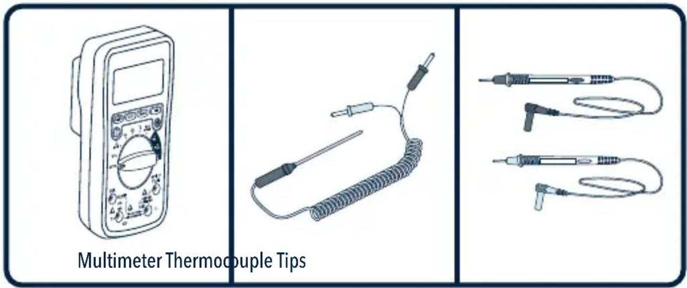
| Accessories | Test leads, thermocouple (K-type), carry case |
| Warranty | 1 year |
Frequently Asked Questions - MUL-650 Steren
User questions about MUL-650 Steren
0 question about this device. Answer the ones you know or ask your own.
Ask a new question about this device
Download the instructions for your Multimeter in PDF format for free! Find your manual MUL-650 - Steren and take your electronic device back in hand. On this page are published all the documents necessary for the use of your device. MUL-650 by Steren.
USER MANUAL MUL-650 Steren
natural_image
Line drawing of a digital multimeter with dial and control buttons (no text or symbols)Multímetro Termopar Puntas
natural_image
Illustration of a coiled spring with two test probes (no text or symbols)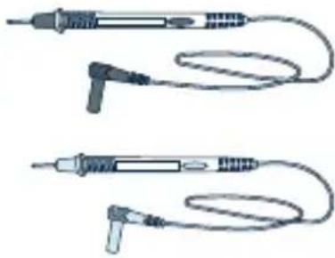
natural_image
Illustration of two types of electrical probes with coiled wires (no text or symbols)DESCRIPCIÓN
PARTES
MODO DE USO

PRECAUCIONES DURANTE EL USO
STEREN PRODUCTO EMPACADO S.A. DE C.V.
Autopista México-Querétaro. Km 26.5 Sin número, Nave Industrial 3-A, Col. Lomas de Boulevares, Tlalnepantla de Baz, Estado de México, C.P. 54020, RFC: SPE-941215-H43
Read these manual to avoid any damage.
The instructions of these manual are for reference about the product.
There may be differences due to update.
Please check our web site www.steren.com to obtain the latest version of the instruction manual.
CAUTIONS
- Improper use of this Multimeter can cause damage, electric shock, or serious injury.
- This product is not a toy; Keep the Multimeter out of the reach of children.
- Always remove test cables before replacing batteries or fuses.
- Check the condition of the test cables and the measurer itself before operating.
- Do not measure voltages exceeding 1000V above ground; Can be risky.
- Be very careful when taking measurements if the voltages are greater than 30 VAC RMS or 60 VDC; These voltages are considered a electric shock danger.
- Always discharge the capacitors and cut off the power of the device before performing diode, resistance or continuity tests.
- To avoid damage to the Multimeter, do not exceed the maximum limits of the input values shown in the specifications.
- In case of a prolonged period of inactivity, remove the battery.
- This appliance is NOT intended for use by persons with different capacities, unless properly prepared and supervised.
- Do not use the Multimeter if the battery cover is not in place and fully closed.
NOTES:
The operation of this device is subject to the following two conditions: (1) it is possible that this device may not cause harmful interference and (2) this device must accept any interference, including interference that may cause undesired operation.
This multimeter can be connected through an application to view the measurement data from a smartphone. Please refer to the complete instruction manual on our website www.steren.com to learn how to download the application and connect via Bluetooth.
INDEX
CONTENT 3
DESCRIPTION 3
PARTS 3
SELECTION KNOB 4
SYMBOLS IN SCREEN 5
PLACING BATTERY 6
HOW TO USE 6
HOW TO CONNECT THE TEST CABLES 6
VOLTAGE MEASUREMENT WITH DIRECT CURRENT AND ALTERNATE CURRENT 7
DIRECT CURRENT AND ALTERNATE CURRENT MEASUREMENT 7
RESISTANCE MEASUREMENT 8
CAPACITANCE MEASUREMENT 8
FREQUENCY AND PERCENTAGE OF THE WORKING CYCLE MEASUREMENT ____9
TEMPERATURE MEASUREMENT 9
BATTERY TESTING 10
DIODES AND CONTINUITY TESTING 10
OTHER FUNCTIONS 11
TEST SPECIFICATIONS 12
DIRECT CURRENT VOLTAGE 12
ALTERNATE CURRENT VOLTAGE 12
DIRECT CURRENT 13
ALTERNATING CURRENT 13
RESISTANCE 13
CAPACITANCE 14
FREQUENCY 14
WORKING CYCLE 14
TEMPERATURE 14
BATTERY TESTING 15
DIODES AND CONTINUITY TESTING 15
CONTENT
DESCRIPTION
PARTS
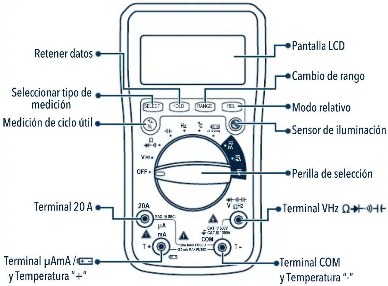
■ SELECTION KNOB
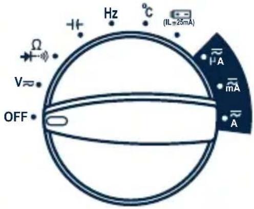 | OFF Turn off |
| V≈ Direct Current and Alternating Current Voltage | |
| Ω Resistance, diodes and continuity | |
| -1+ Capacitance | |
| Hz Frequency | |
| °C Temperature in Celsius degrees | |
| (EL=25mA) Battery Measurement | |
| μA Direct current and alternating current in micro amps | |
| mA Direct current and alternating current in milli amps | |
| A Direct current and alternating current in amps |
■ SYMBOLS IN SCREEN
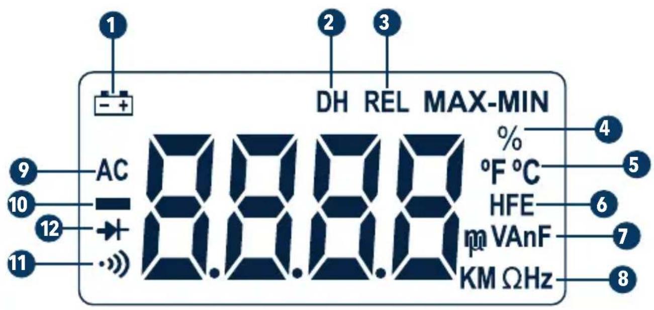
| 1 | Low battery |
| 2 | Hold data |
| 3 | Relative mode |
| 4 | Working cycle measurement |
| 5 | Degrees: Celsius / Fahrenheit |
| 6 | Transistors measurement |
| 7 | Voltage unit: Volts / milli voltsCurrent unit: Micro ampere / mili ampere / ampereCapacitance unit: nano farad/ micro farad / mili farad / farad |
| 8 | Resistance unit: Kilo ohms / mega ohms / ohmsFrequency unit: Kilo hertz / mega hertz / hertz |
| 9 | Alternating current |
| 10 | Direct current |
| 11 | Continuity measurement |
| 12 | Diodes |
PLACING BATTERY
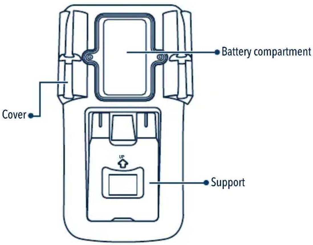
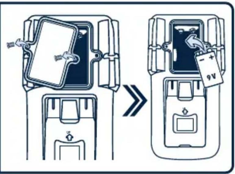
Remove the screws and the battery compartment cover using a screwdriver, and insert a "9V" battery.
Be sure to place the battery polarity correctly.
If the - + symbol appears on the screen, it means that you must replace the battery.
HOW TO USE

CAUTIONS DURING USING

- To avoid the electric shock risk, do not connect the test tips if the Multimeter cover is not in place.
- The selection knob must be in the correct position for the test.
- To avoid electric shock and damage in the Multimeter, do not exceed the maximum values shown in the specifications.
- Never change the knob position of the at random during the measurement.
- To avoid electrical shock or damage in the Multimeter, do not attempt to take any voltage measurements exceeding 60 VDC and 30 VAC.
- The protective fuse must be only replaced by one of the same type and specification.
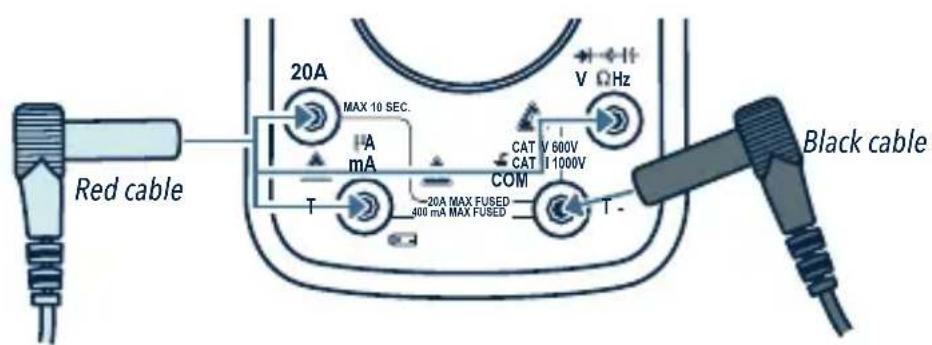
■ HOW TO CONNECT THE TEST CABLES
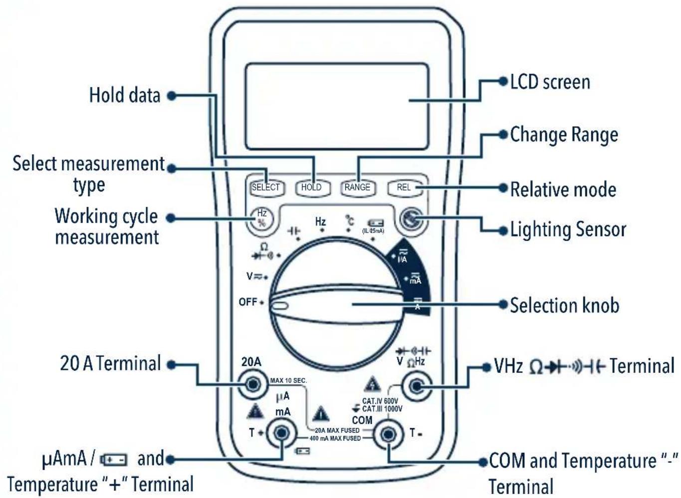
Insert the black cable connector into the COM terminal.
Insert the red cable connector on the 20 A, μA mA or V Ω Hz terminals.
■VOLTAGE MEASUREMENT WITH DIRECT CURRENT AND ALTERNATE CURRENT
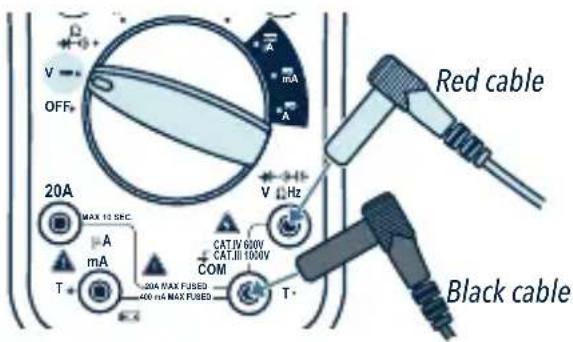
1 Connect the black test cable in to the COM terminal and the red test cable in to the VΩ Hz terminal.
2 Turn the knob to V ≈ position, to measure the DC (Direct Current) voltage. If you want to measure the AC (Alternating current) voltage, press the "SELECT" button.
3 Tap the circuit with tips. The measurement value will be displayed.
NOTES:
- "△" It means that you can not enter more than 1000 V; a higher voltage may be displayed, but may damage the circuit or cause an electric shock.
- Be careful of electrical shocks when measuring high voltage.
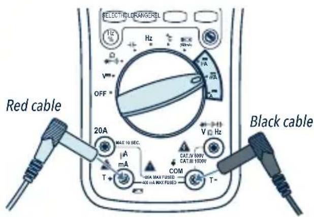
■ DIRECT CURRENT AND ALTERNATE CURRENT MEASUREMENT
1 Connect the black test cable to the COM terminal and the red test cable in to the A mA to measure a maximum current of 400 mA. To measure a maximum current of 2 A or 20 A, connect the red wire to the 20 A terminal.
2 Turn the knob to A , mA or A position as required.
If you want to measure Direct Current. If you want to measure AC (Alternating Current), press the "SELECT" button.
3 Tap the circuit with tips. The measurement value will be displayed.
NOTES:
- If "OL" appears in the display, means the input value exceeds the selected range.
- "△" means that the mA maximum current of the plug is 400 mA and the maximum current 20 A, if the measurement is over 400 mA it will be protected by the fuse but if the current is greater than 20 A the fuse will be burn
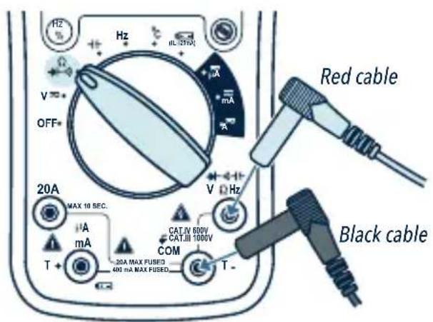
■RESISTANCE MEASUREMENT
1 Connect the black test cable in to the COM terminal and the red test cable in to the VΩ Hz terminal.
2 Turn the knob to the ^ position.
3 Tap the circuit with tips. The measurement value will be displayed.
NOTES:
- If you measure resistors greater than 1 MΩ, the Meter may take a few seconds to obtain a stable reading.
- When the terminal is not connected, it means, in open circuit, the "OL" icon will be displayed indicating that it is over the range.
- Make sure that the circuits are out of power and capacitors are fully discharged to prevent electrical shock or damage to the device.
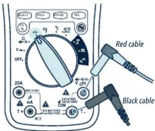
CAPACITY MEASUREMENT
1 Connect the black test cable in to the COM terminal and the red test cable in to the V Ω Hz terminal.
2 Turn the knob to the +1 position.
3 Tap the circuit with tips or wire that you want to check. The measurement value will be displayed.
NOTE:
Make sure that the circuits are out of power and the capacitors are fully discharged to prevent electric shocks or damages to the device.
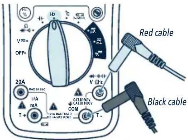
■ FREQUENCY AND PERCENTAGE OF THE WORKING CYCLE MEASUREMENT
1 Connect the black test cable in to the COM terminal and the red test cable in to the VΩ Hz terminal.
2 Turn the knob to Hz position.
3 Press the "Hz / %" button or choose the frequency test or the percentage of the working cycle.
4 Tap the circuit with tips. The measurement value will be displayed.
■ TEMPERATURE MEASUREMENT
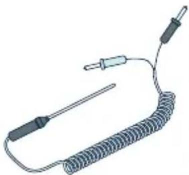
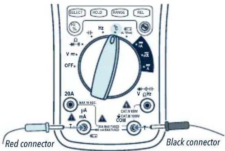
1 Insert the black thermocouple connector into the T-terminal and insert the red connector into the T+ terminal.
2 Turn the knob to the °C position.
3 Tap with the tip the piece whose temperature you want to measure; Hold the contact until the reading stabilizes.
BATTERY TESTING
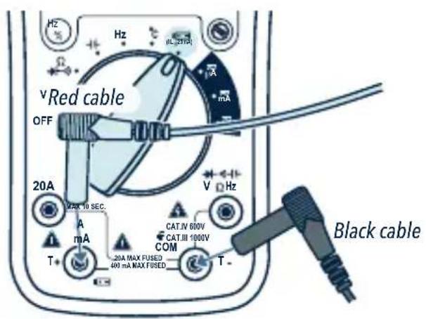
1 Connect the black test cable in to the COM terminal and the red test lead in to the terminal
2 Turn the knob to the (1L=25mA) position.
3 Tap the circuit with tips. The measurement value will be displayed.
■ DIODES AND CONTINUITY TESTING
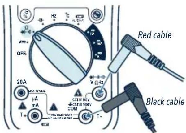
1 Connect the black test cable in to the COM terminal and the red test cable in to the VΩ Hz terminal.
2 Turn the knob to position.
3 Press the "SELECT" button to select diode or continuity measurement.
4 To measure diodes connect the tips to the semiconductor component: the red to the anode and the black to the cathode.
To measure continuity, tap with tips the circuit or wire that you want to check. The measurement value will be displayed.
NOTE:
Make sure that the circuits are out of power and the capacitors are fully discharged to prevent electric shocks or damages to the device.
OTHER FUNCTIONS
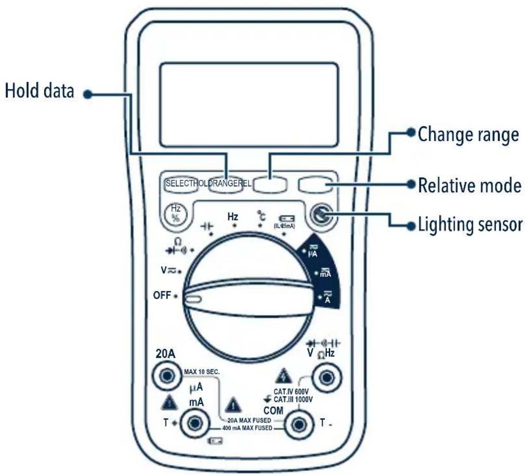
| Hold data | After performing a measurement press once to hold the reading on the screen. |
| Change range | Press to select between auto or manual range. |
| Relative mode | After taking a measurement (reference value) press REL. Then take a second measurement.The displayed value is the difference between the two values. |
| Lighting sensor | The light on the screen will automatically turn on in low light conditions. |
TEST SPECIFICATIONS
■ DIRECT CURRENT VOLTAGE
| RANGE RESOLUTION ACCURACY | ||
| 400 mV 0.1 mV | ±(0.5% of reading + 2 digits) | |
| 4 V 1 mV | ||
| 40 V | 10 mV | |
| 400 V | 100 mV | |
| 1 000 V | 1 V | ±(0.8% of reading + 2 digits) |
Impedance: 10 MΩ
Overload protection: 250 V DC or AC rms of 400 mV range, 1 000 DC or 750 V AC rms for other ranges
■ ALTERNATING CURRENT VOLTAGE
| RANGE RESOLUTION ACCURACY | ||
| 400 mV 0.1 mV | ±(1.2 % of reading + 3 digits) | |
| 4 V 1 mV | ±(0.8 % of reading + 3 digits) | |
| 40 V | 10 mV | |
| 400 V | 100 mV | |
| 750 V | 1 V | ±(1.2 % of reading + 3 digits) |
The 400 mV range only select it with the button "RANGE".
Impedance: 10 MΩ, more than 100 MΩ over the 400 mV range
Overload protection: 250 V DC or AC rms of 400 mV range, 1 000 DC or 750 V AC rms for other ranges
Frequency range: 40 to 400 Hz
Response: Average, calibrated in sine wave rms
DIRECT CURRENT
| RANGE RESOLUTION | ACCURACY | |
| 400 μA 0.1μA | ±(1.2% of reading + 2 digits) | |
| 4 000 μA 1μA | ||
| 40 mA | 10 μA | |
| 400 mA | 100 μA | |
| 4 A | 1 mA | ±(2.0% of reading + 3 digits) |
| 20 A | 10 mA | |
Overload protection: 400 mA / 250 V Fuse
F-20 A /250 V Fuse, 20 A up to 10 seconds
■ALTERNATING CURRENT
| RANGE RESOLUTION | ACCURACY | |
| 400 μA 0.1μA | ±(1.5 % of reading + 3 digits) | |
| 4 000 μA 1μA | ||
| 40 mA | 10 μA | |
| 400 mA | 100 μA | |
| 4 A | 1 mA | ±(2.5 % of reading + 5 digits) |
| 20 A | 10 mA | |
Overload protection: 400 mA / 250 V Fuse
Fusible F-20 A / 250 V, 20 A up to 10 seconds
Frequency range: 40 up to 400 Hz
RESISTANCE
| RANGE RESOLUTION | ACCURACY | |
| 400 Ω 0.1Ω | ±(1.0 % of reading + 3 digits) | |
| 4 kΩ 1Ω | ±(1.0 % of reading + 2 digits) | |
| 40 kΩ | 10 Ω | |
| 400 kΩ | 100 Ω | |
| 4 MΩ | 1 kΩ | |
| 40 MΩ | 10 kΩ | ±(1.5 % of reading + 3 digits) |
Overload protection: 250 V DC or AC rms
CAPACITANCE
| RANGE RESOLUTION | ACCURACY | |
| 51.2 nF 10 pF | ±(3.0 % of reading + 10 digits) | |
| 512 nF 100 pF | ±(2.5 % of reading + 5 digits) | |
| 5.12 μF | 1 nF | |
| 51.2 μF | 10 nF | |
| 4 100 μF | 100 nF | ±(5.0 % of reading + 10 digits) |
Overload protection: 250 V DC or AC rms
FREQUENCY
| RANGE RESOLUTION | ACCURACY | |
| 5.12 Hz 0.001 Hz | ±(0.1% of reading + 5 digits) | |
| 51.2 Hz 0.01 Hz | ||
| 512 Hz | 0.1 Hz | |
| 5,12 kHz | 1 Hz | |
| 51.2 kHz | 10 Hz | |
| 512 kHz 100 Hz | ||
| 5.12 MHz | 1 kHz | |
Sensitivity: sine wave 0.6 V rms (5.12 MHz: 1.5 V rms)
Overload protection: 250 V DC or AC rms
WORKING CYCLE
0.1% \~ 99.9% ± (2.0% of reading + 2 digits), Frequency less than 10 kHz
Sensitivity: sine wave 0.6 V rms
Overload protection: 250 V DC or AC rms
TEMPERATURE
| RESOLUTIONRANGE ACCURA | |||
| °C 1 °C | -20 150 °Cto | ±(3 °C + 1 digit) | |
| 150 to 1 000 °C | ±(3 % of reading + 2 digits) | ||
BATTERY TESTING
| TEST CONDITIONRANGE ACCURA | ||
 | Charging current: Approx. 25 mA±(50% of |
Battery voltage range: 1.5 V \~ 12 V
Overload protection: 400 mA / 250 V Fuse
■DIODES AND CONTINUITY TESTING
| TEST CONDITIONRANGE DESCR | ||
 | Approximate diode voltage reading | Direct current approx. 0.4 mAInverted voltage approx. 1.5 V |
 | A buzz will sound if resistance is less than 100 Ω | Open circuit voltage approx. 0.5 V |
Battery voltage range: 1.5 V \~ 12 V
Overload protection: 250 V DC or AC rms
The Multimeter has the serial data output function. It can be connected to the mobile phone by Bluetooth, so the data of the multimeter can be recorded, analyzed, and processed by the mobile phone APP. Before using this feature, you must install the mobile phone APP. Download it in PLAYSTORE for android and in Appstore for iphone.

flowchart
graph LR
    A["Android robot"] --> B["Google Play"]
    B --> C["Bluetooth Multimeter"]
    C --> D["Android App"]
NOTE: The mobile phone APP can be installed on android system 4.30 or higher.

flowchart
graph LR
    A["App Store"] --> B["Download on the App Store"]
    B --> C["Bluetooth Multimeter"]
    C --> D["iPhone App"]
NOTE: The mobile phone APP can be installed on iOS 4S or higher.
1 Make sure that the mobile phone application has been installed correctly before any measurement.
2 Open the Bluetooth of the mobile phone and perform the application to enter in the main interface.
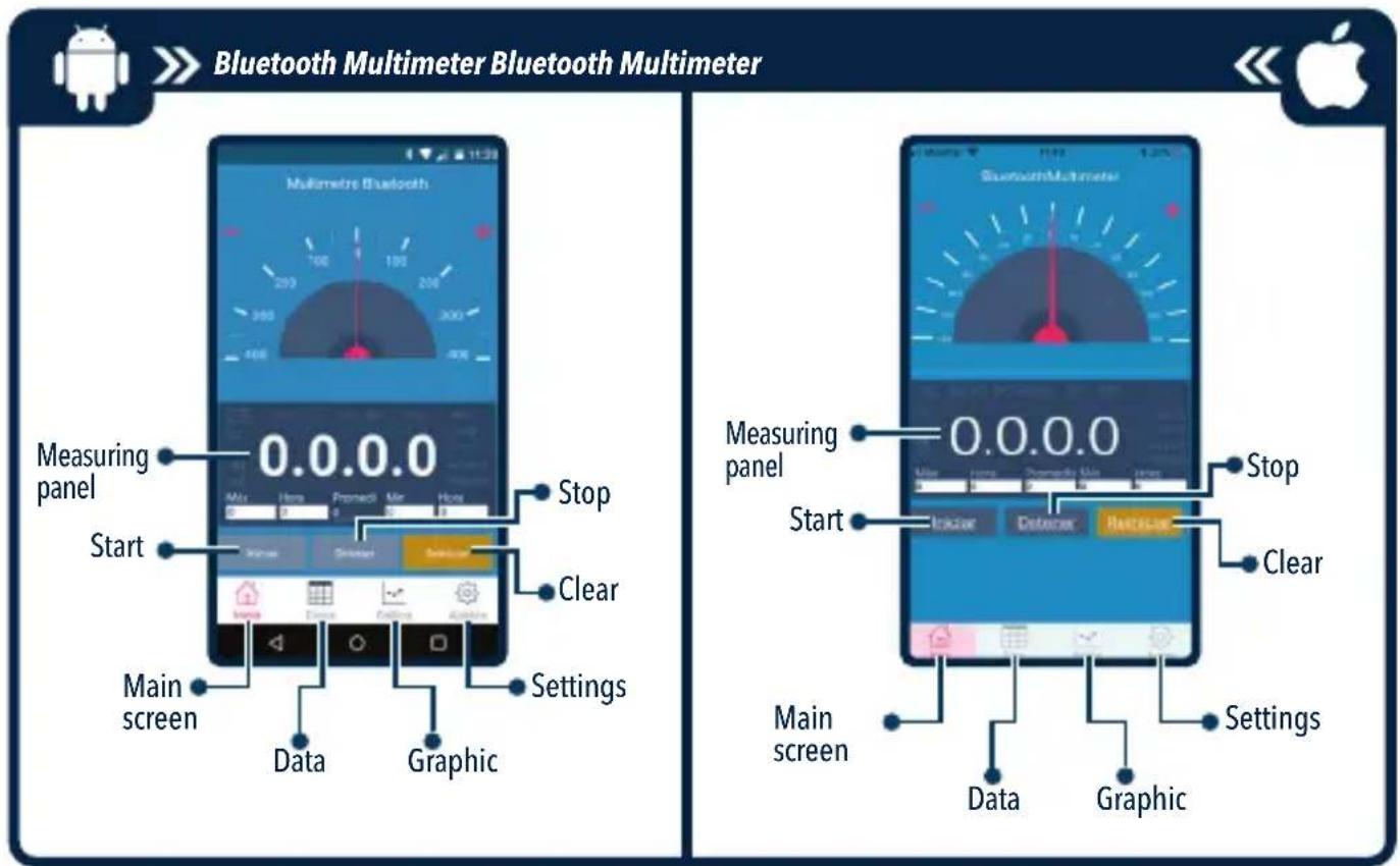
3 Turn on the multimeter, it will connect to the mobile phone automatically, when the "Iniciar" key changes to green color, click to measure and view synchronized data or graphics.

4 The MAX or MIN value and corresponding time will be displayed in the mobile phone APP, and the average value in a period of time from the start measurement will also be displayed.
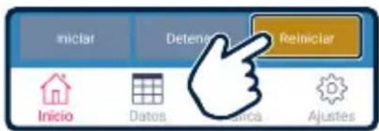
5 Press "Reiniciar" to reset the measurement, the old data will be erased and data recording will resume. Press the "Detener" key to stop the connection.

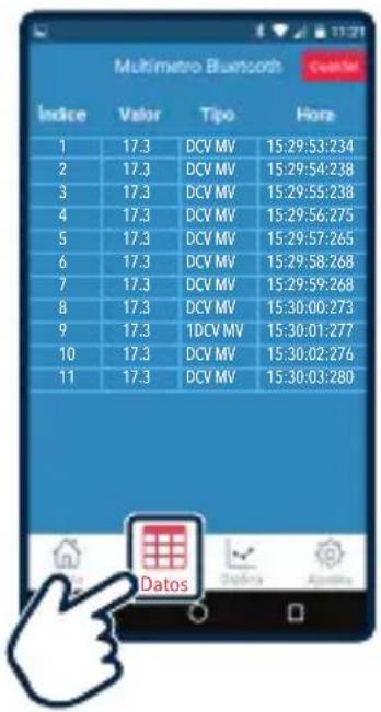
Datos: to view data and time.
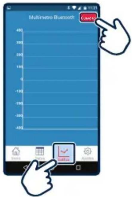
Gráfica: to view graphic.
Guardar: to save data or graphic.
Inicio: to return to the main interface.
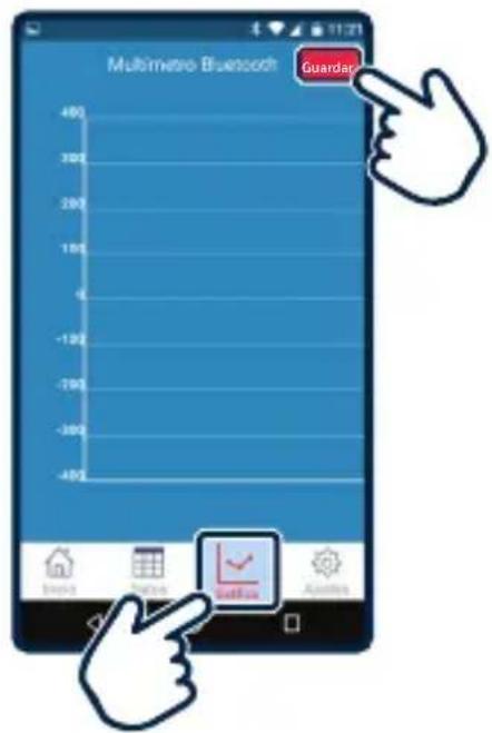
To view saved files, search folder with the specified name when saving
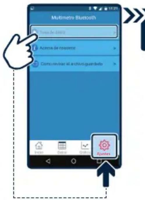
To change the data saving time go to "Ajustes" and click on Tasa de datos
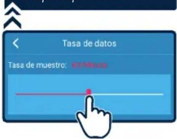
A slide bar will appear and will indicate how many measurements are saved per minute
Example: 60 per minute
Input: 9 V --- (square battery)
DC voltage (V): 400 mV / 4 V / 40 V / 400 V ±(0.5%+2d) / 1 000 V ±(0.8%+2d)
AC voltage (V) True-RMS: 4 V / 40 V / 400 V ±(0.8%+3d) / 750 V ±(1.2%+3d)
DC current (A): 400 uA / 4 000 uA / 40 mA / 400 mA ±(1.2%+2d)
DC current (A): 4 A / 20 A ±(2%+3d)
AC current (A): 400 uA / 4 000 uA / 40 mA / 400 mA ±(1.5%+3d)
AC current (A): 4 A / 20 A ±(2.5%+5d)
Resistance (Ω): 400 ±(1%+3d) / 4 K / 40 K / 400 K / 4 M ±(1%+2d) / 40 M ±(1.5%+3d)
Capacitance: 51.2 nF ±(3%+10d) / 512 nF / 5.12 uF / 51.2 uF ±(2.5%+5d) / 100 uF ±(5%+10d)
Frequency (Hz): 5.12 Hz / 51.2 Hz / 512 Hz / 5.12 kHz / 512 kHz / 5.12 MHz ±(0.1%+5d)
Temperature: -20 to 150°C ±(3°C+1d) / 150 to 1 000 °C ±(3%+2d)
Operating temperature: 0 - 40 °C
Storing temperature: -20 to 60°C
Consumption: 0.1 mW/h
Stand by power consumption: not applicable
Product: Bluetooth professional multimeter
Part number: MUL-650
Brand: Steren
WARRANTY
This Steren product is warranted under normal usage against defects in workmanship and materials to the original purchaser for one year on the other parts from the date of purchase.
CONDITIONS
- This warranty card with all the required information, invoice or purchase ticket, product box or package, and product, must be presented when warranty service is required.
- If the product is in the warranty time, the company will repair it free of charge. The supplier will pay for transportation charges.
- The repairing time will not exceed 30 natural days, from the day the claim was received.
- Steren sell parts, components, consumables and accessories to customer, as well as warranty service, at any of the addresses mentioned later.
THIS WARRANTY IS VOID IN THE NEXT CASES:
If the product has been damaged by an accident, acts of God, mishandling, leaky batteries, failure to follow enclosed instructions, improper repair by unauthorized personnel, improper safe keeping, among others.
a) The consumer can also claim the warranty service in the purchase establishment.
b) If you lose the warranty card, we can reissue it, if you show the invoice or purchase ticket.
ELECTRÓNICA STEREN S.A. DE C.V.
Biólogo Maximino Martínez No. 3408, San Salvador Xochimanca, Del. Azcapotzalco Ciudad de México 02870, RFC: EST850628-K51
STEREN PRODUCTO EMPACADO S.A. DE C.V.
Autopista México-Querétaro. Km 26.5 Sin número, Nave Industrial 3-A, Col. Lomas de Boulevares, Tlalnepantla de Baz, Estado de México, C.P. 54020, RFC: SPE-941215-H43
RETAILER INFORMATION
Name of the retailer
Address
Serial number
Product
In case your product fails or have questions, please contact your nearest dealer.
If you are in Mexico, please call to our Call Center.
Call Center 01 800 500 9000

natural_image
Empty white square with a dark blue border (no text or symbols)
www.steren.com
- DESCRIPCIÓN
- PARTES
- MODO DE USO
- PRECAUCIONES DURANTE EL USO
- STEREN PRODUCTO EMPACADO S.A. DE C.V.
- CAUTIONS
- NOTES:
- INDEX
- CONTENT 3
- DESCRIPTION 3
- PLACING BATTERY 6
- HOW TO USE 6
- OTHER FUNCTIONS 11
- TEST SPECIFICATIONS 12
- CONTENT
- DESCRIPTION
- ■ SELECTION KNOB
- PLACING BATTERY
- HOW TO USE
- CAUTIONS DURING USING
- ■ HOW TO CONNECT THE TEST CABLES
- ■VOLTAGE MEASUREMENT WITH DIRECT CURRENT AND ALTERNATE CURRENT
- ■ DIRECT CURRENT AND ALTERNATE CURRENT MEASUREMENT
- ■RESISTANCE MEASUREMENT
- CAPACITY MEASUREMENT
- NOTE:
- ■ FREQUENCY AND PERCENTAGE OF THE WORKING CYCLE MEASUREMENT
- ■ TEMPERATURE MEASUREMENT
- BATTERY TESTING
- ■ DIODES AND CONTINUITY TESTING
- OTHER FUNCTIONS
- TEST SPECIFICATIONS
- ■ DIRECT CURRENT VOLTAGE
- ■ ALTERNATING CURRENT VOLTAGE
- WORKING CYCLE
- ■DIODES AND CONTINUITY TESTING
- WARRANTY
- CONDITIONS
- THIS WARRANTY IS VOID IN THE NEXT CASES:
- RETAILER INFORMATION
Brand : Steren
Model : MUL-650
Category : Multimeter