
Microflex MX393 - Microphone SHURE - Free user manual and instructions
Find the device manual for free Microflex MX393 SHURE in PDF.


| Product type | Boundary microphone |
| Brand | Shure |
| Model | Microflex MX393 |
| Category | Professional microphone |
| Transducer | Electret condenser |
| Polar pattern | Cardioid |
| Frequency response | 50 Hz – 17 000 Hz |
| Output impedance | 150 Ω (balanced) |
| Sensitivity (at 1 kHz, open circuit) | -32 dBV/Pa (25 mV/Pa) |
| Power requirement | Phantom power 11–52 V DC |
| Output connector | XLR male 3-pin |
| Dimensions (L × l × H) | 107 × 64 × 23 mm |
| Net weight | 0.5 kg |
| Housing material | Die-cast zamak |
| Finish | Matte black |
| Operating temperature | -30 °C to +74 °C |
| Relative humidity | 0 to 95 % (non-condensing) |
| Key features | Clear speech capture for conferences, meeting tables, and courtrooms. Low-profile discreet design. Adjustable DIP switch for low-cut filter and attenuation. |
| Care and cleaning | Wipe with a soft, dry cloth. Do not use solvents or abrasive cleaners. Disconnect before cleaning. |
| Safety | Do not disassemble. No user-serviceable parts. Risk of electric shock if housing is opened. Use only with phantom power compatible equipment. |
| Spare parts and repairability | Contact Shure customer service or an authorized dealer for repairs. No spare parts available for the general public. |
| General information | 2-year warranty (depending on country). Certified compliant with CE and FCC standards. Made in China. |
Frequently Asked Questions - Microflex MX393 SHURE
User questions about Microflex MX393 SHURE
0 question about this device. Answer the ones you know or ask your own.
Ask a new question about this device
Download the instructions for your Microphone in PDF format for free! Find your manual Microflex MX393 - SHURE and take your electronic device back in hand. On this page are published all the documents necessary for the use of your device. Microflex MX393 by SHURE.
USER MANUAL Microflex MX393 SHURE
natural_image
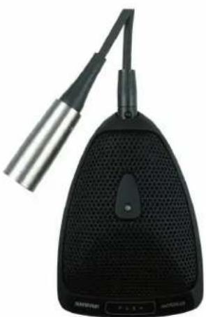
Black electronic device with ventilation grille and cable, no visible text or symbolsMX392 MX393
natural_image
Black desktop microphone with adjustable neck and front-mounted probe (no visible text or symbols)MX300 Boundary Microphones
Shure Microflex® MX300 Series microphones are surface-mounted electret condenser microphones designed primarily for mounting on conference tables, stage floors, and lecterns. Their high sensitivity and wide frequency range make them especially suitable for picking up speech and vocals in sound reinforcement and recording applications. Interchangeable cartridges provide the installer with greater flexibility and make it possible to easily reconfigure microphone coverage as the need arises. The MX392 and MX393 models include an internal preamplifier.
MX300 Series microphones take advantage of the principle that, at a barrier or boundary, the sound pressure level doubles. When placed near a sufficiently large boundary surface, the microphone has 6 dB higher sensitivity and approximately 3 dB greater direct-to-reverberant sound ratio.
Features
- Flat frequency response across the vocal range for uncolored sound
- Interchangeable cartridges that provide a choice of polar pattern for each application
- Sleek, low-profile design for surface mounting
- Programmable mute button
- LED indicator
- Logic input/output for remote control or use with automatic mixers (MX392 models only)
- RF filtering
Model Variations
MX392: Attached, unterminated cable and programmable logic input and output.
MX393: Detachable cable with XLR output connector.
The polar pattern of the included cartridge is indicated by a model number suffix:
/C Cardioid
/S Supercardioid
/○ Omnidirectional
Interchangeable Cartridges
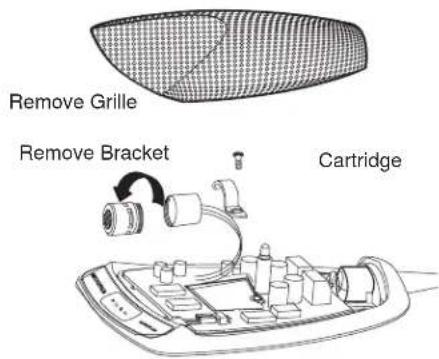
Microflex microphones use interchangeable cartridges that allow you to choose the polar pattern for different installations.
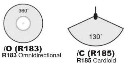
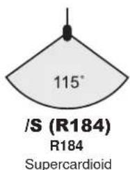
Permanent Installation
MX392 & MX393
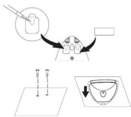
- Remove grille to access mounting key holes.
- Cut slots into pads.
- Slide microphone forward to engage screws in slots.
If using rear side-exit cable option, only drill two outer holes. If re-routing for cable bottom exit, (MX392 only), drill all three holes.
Microphone Placement
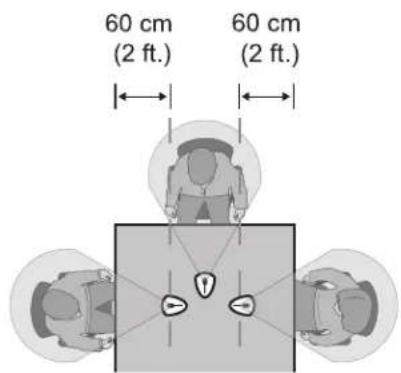
For best low-frequency response and rejection of background noise, place the microphone on a large, flat surface, such as a floor, table, or lectern.
To reduce reverberance, avoid reflective surfaces above or to the side of the microphone, such as beveled sides of pulpits or overhanging shelves.
Configuration
DIP Switches
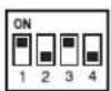
Use the DIP switches to configure logic settings and mute button behavior.
The DIP switches are covered with a piece of clear tape at the factory. Remove tape to modify the switch settings.
NOTE: Bottom cover must be closed for microphone to function.
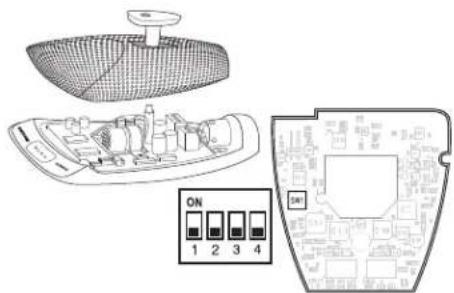
| OFF (factory default) | ON | |
| 1 | Momentary Toggle | |
| 2 | Push-to-mute Push-to-talk | |
| 3 | Mute button enabled, LED illuminates when mic is active | Disable mute button (microphone always on), logic controls LED |
| 4 -- | -- |
Wiring
Mute Button Configuration
Use DIP switches 1 and 2 to configure the mute button, as follows.
Be sure to set DIP switch 3 off (factory default) so that the mute button controls audio from the microphone.
| Switch Function DIP Switch Setting | |
| Momentary: push-to-mute(as shipped). |  ____ ____ |
| Momentary: push-to-talk |  |
| Toggle: (Push On/Push Off): Mic is active when powered on |  ____ ____ |
| Toggle: (Push On/Push Off): Mic is mute when powered on |  |
Connecting to an Automatic Mixer
Use these settings if connecting the microphone to an automatic mixer or other device that mutes audio and controls the LED.
- Connect logic leads to the automatic mixer. Connect the LED IN to the gate output to illuminate the LED when that channel is gated on.
- Set DIP switch 3 on. This disbles the mute button (the microphone passes audio regardless of whether the button is pressed or not).
- Set DIP switch 1 to configure how the mute button sends SWITCH OUT logic:
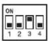
Momentary: push = 0 Vdc, release = 5 Vdc
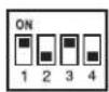
Toggle: initial = 5 Vdc, push = 0 Vdc
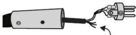
Logic Wiring
natural_image
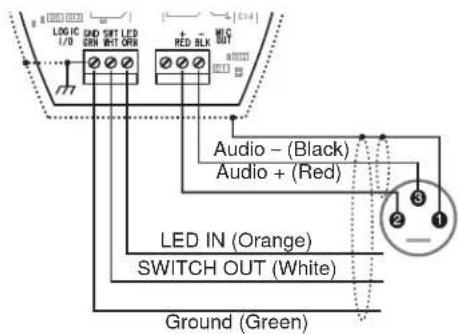
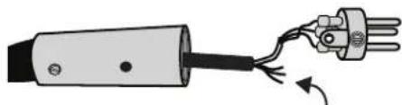
Diagram of a soldering iron plug with three terminal pins and a curved wire, showing electrical contact (no text or symbols)Green (LOGIC GROUND): Connects to the logic ground of an automatic mixer, switcher, or other equipment.
Orange (LED IN): Set DIP switch 3 on to use LED IN. When shorted to LOGIC GROUND, the LED turns on.
White (SWITCH OUT): Provides TTL logic (0 Vdc or 5 Vdc) in response to the mute button. Set DIP switch 1 for momentary or toggle. When phantom power is applied, logic initializes high (5 Vdc). DIP switch 2 has no effect on SWITCH OUT.
Changing SWITCH OUT to Always Momentary
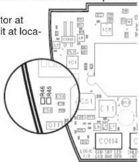
Use the following modification in situations where your logic interface requires momentary closure of the SWITCH OUT, but you want the mute button to toggle the microphone (DIP switch 1 ON, 3 OFF):
- Access the circuit board inside the microphone base.
- Remove the resistor at R45 and reinstall it at location R46.
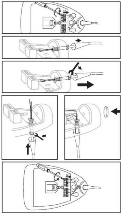
Re-Routing Cable for Bottom Exit (MX392 Only)
- Remove the grille.
- Disconnect wires from screw terminals.
- Grasp rubber boot within 1/2" of housing, using gas pliers. Rotate boot and cable ccw to remove connector from threaded "L" bracket.
- Remove cable from microphone housing.
- Insert cable through access hole in microphone base.
- Insert cable connector through hole and thread it into "L" bracket.
- If desired, rubber strain relief can be reattached to cable end or removed from cable before fastening it to bracket.
- Re-connect wires to proper screw terminals on circuit board.
- Insert supplied round rubber plug into unused side cable exit.
- Reinstall grille and foam screen.
- Insert cable through hole in mounting surface. Secure microphone to mounting surface.
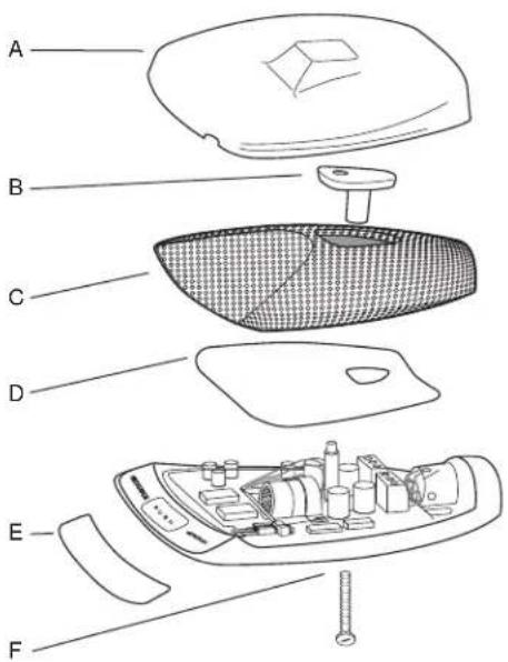
Painting
A supplied plastic paint shield
B retainer
C grille
D foam screen
E supplied adhesive masking strip
F supplied rubber plug
1. Remove foam screen from grille before painting
2. Clean surfaces to be painted with denatured alcohol or naphtha.
3. To avoid filling grille holes, apply paint in thin layers.
4. Important: Use fine sandpaper to remove paint from the bottom edges of the grille. This ensures electrical continuity for proper shielding.
Specifications
Type
Condenser (electret bias)
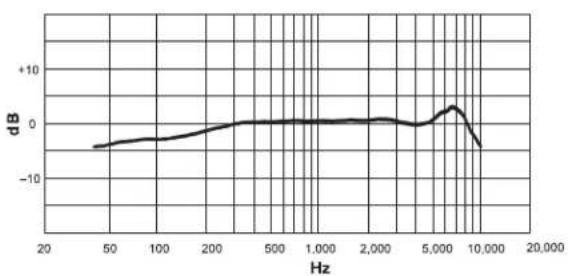
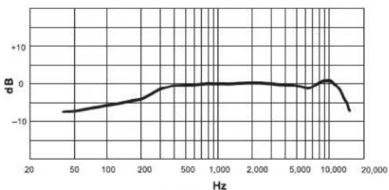
Frequency Response
50–17000 Hz
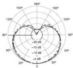
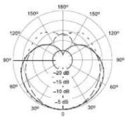
Polar Pattern
MX412D/C, MX418D/C: Cardioid
MX412D/S, MX418D/S: Supercardioid
Output Impedance
EIA Rated at 150 Ω (180 Ω actual)
Output Configuration
Active balanced
Sensitivity (at 1 kHz, open circuit voltage)
Cardioid: -34 dBV/Pa (21 mV)
Supercardioid: -33 dBV/Pa (24 mV)
Omnidirectional: -28 dBV/Pa (40 mV)
1 Pascal=94 dB SPL
Maximum SPL (1 kHz at 1% THD, 1 kΩ load)
Cardioid: 123 dB
Supercardioid: 122 dB
Omnidirectional: 117 dB
Equivalent Output Noise (A-weighted)
Cardioid: 29 dB SPL
Supercardioid: 28 dB SPL
Omnidirectional: 71 dB SPL
Signal-to-Noise Ratio (referenced at 94 dB
SPL at 1 kHz)
Cardioid: 65 dB
Supercardioid: 66 dB
Omnidirectional: 71 dB
Dynamic Range (1 kΩ load at 1 kHz)
94 dB
Common Mode Rejection (10 Hz to 100 kHz)
45 dB minimum
Preamplifier Output Clipping Level (1% THD)
-6 dBV (0.5 V)
Polarity
Positive sound pressure on diaphragm produces positive voltage on pin 2 relative to pin 3 of output XLR connector.
Net Weight
MX412D: 0.81 kg (1.80 lbs)
MX418D: 0.82 kg (1.82 lbs)
Packaged Weight
MX412D: 1.63 kg (3.62 lbs)
MX412D: 1.64 kg (3.64 lbs)
Logic Connections
LED IN: Active low (≤1.0V), TTL compatible.
Absolute maximum voltage: -0.7V to 50V.
LOGIC OUT: Active low (≤1.0V), sinks up to
20mA, TTL compatible. Absolute maximum voltage: -0.7V to 50V (up to 50V through 3kΩ).
Mute Switch Attenuation
-50 dB minimum
Cable
3 m (10 ft) attached cable with shielded audio pair terminated at a 3-pin male XLR and three
unterminated conductors for logic control
Environmental Conditions
Operating Temperature: -18–57 °C (0–135 °F)
Storage Temperature: -29–74 °C (-20–165 °F)
Relative Humidity: 0–95%
Power Requirements
11–52 Vdc phantom, 2.0 mA
Furnished Accessories
Zipper Bag 95B2313
Paint Mask 80C514
Switch Paint Mask 80A541
Paint Plug 36A664
Replacement Parts
Omnidirectional Cartridge (Black) R183B
Supercardioid Cartridge (Black) R184B
Cardioid Cartridge (Black) R185B
12' (3.7m) Cable 3-Pin Miniature
Connector (TA3F) to male XLR C129
(MX393)
Custom Logic Cable (specify 95R2509
length) 95B2509
Custom logic cable with threaded G130
adapter (MX392) C130
CERTIFICATION
Eligible to bear CE Marking. Conforms to
European EMC Directive 2004/108/EC. Meets
Harmonized Standards EN55103-1:1996 and
EN55103-2:1996, for residential (E1) and light industrial (E2) environments.
The Declaration of Conformity can be obtained
from:
Authorized European representative:
Shure Europe GmbH
Headquarters Europe, Middle East & Africa
Department: EMEA Approval
Wannenacker Str. 28
D-74078 Heilbronn, Germany
Phone: +49 7131 72 14 0
Fax: +49 7131 72 14 14
Email: EMEAsupport@shure.de
Alternance : initial = 5 V c.c., appuyer = 0 V c.c.
Bornes logiques
natural_image
Diagram of a soldering iron plug with three terminal pins connected to a wire, showing electrical winding (no text or symbols)natural_image
Diagram of a mechanical or electrical component with labeled parts and directional arrows (no readable text or symbols)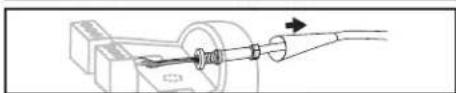
natural_image
Pure mechanical assembly diagram showing a pipe connection with a directional arrow (no text or symbols)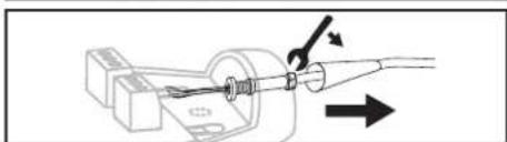
natural_image
Diagram of a mechanical assembly with a tool and directional arrow (no text or symbols)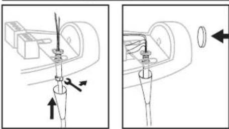
natural_image
Technical diagram showing two mechanical assembly steps with arrows indicating movement (no text or symbols)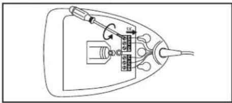
Peinture
MX412D: 1.63 kg (3.62 lbs)
MX412D: 1.64 kg (3.64 lbs)
Connexions logiques
11–52 V c.c. fantôme, 2,0 mA
Accessoires fournis
D-74078 Heilbronn, Germany
Phone: +49 7131 72 14 0
Fax: +49 7131 72 14 14
Email: EMEAsupport@shure.de
Mikrofonaufstellung
natural_image
Diagram of a soldering iron plug with three terminal pins and a curved wire, showing electrical contact (no text or symbols)MX412D: 1.63 kg (3.62 lbs)
MX412D: 1.64 kg (3.64 lbs)
Logikanschlüsse
11–52 V DC Phantomspeisung, 2,0 mA
Headquarters Europe, Middle East & Africa
D-74078 Heilbronn, Germany
Tel: +49 7131 72 14 0
Fax: +49 7131 72 14 14
Email: EMEAsupport@shure.de
natural_image
Diagram of a plug with wires and a terminal connector, no text or symbols presentMX412D: 1.63 kg (3.62 lbs)
MX412D: 1.64 kg (3.64 lbs)
Conexiones lógicas
D-74078 Heilbronn, Germany
Phone: +49 7131 72 14 0
Fax: +49 7131 72 14 14
Email: EMEAsupport@shure.de
natural_image
Diagram of a soldering iron plug with three terminal pins connected to a terminal outlet (no text or symbols)MX412D: 1.63 kg (3.62 lbs)
MX412D: 1.64 kg (3.64 lbs)
Collegamenti logici
D-74078 Heilbronn, Germany
Phone: +49 7131 72 14 0
Fax: +49 7131 72 14 14
Email: EMEAsupport@shure.de
MX300
バウンダリーマ
イクロホン
マイクロホンの配置
ミュートボタン設定
natural_image
Diagram of a soldering iron plug with three terminal pins, showing winding and pin connections (no text or symbols)MX412D: 1.63 kg (3.62 lbs)
MX412D: 1.64 kg (3.64 lbs)
ロジックコネクター
D-74078 Heilbronn, Germany
Phone: +49 7131 72 14 0
Fax: +49 7131 72 14 14
Eメール:EMEAsupport@shure.de
line
| Hz | dB | |-------|--------| | 20 | -5.0 | | 50 | -3.0 | | 100 | -2.0 | | 200 | -1.0 | | 500 | 0.0 | | 1,000 | 0.0 | | 2,000 | 0.0 | | 5,000 | 2.0 | | 10,000| -5.0 |CARDIOID
CARDIOIDE CARDIOIDE
KARDIOID CARDIOIDE
radar
| Angle | Value | |---|---| | 0° | -20 dB | | 30° | -15 dB | | 60° | -10 dB | | 90° | -5 dB | | 120° | -10 dB | | 150° | -15 dB | | 180° | -20 dB |250 Hz
--- 500 Hz
— — — 1000 Hz
radar
| Angle | Value | |---|---| | 0° | -20 dB | | 30° | -15 dB | | 60° | -10 dB | | 90° | -5 dB | | 120° | 0 dB | | 150° | 5 dB | | 180° | 10 dB | | 210° | 15 dB | | 240° | 20 dB | | 270° | 25 dB | | 300° | 30 dB | | 330° | 35 dB | | 360° | 40 dB |2600 Hz
- - - - 6400 Hz
— — — 10000 Hz
CARDIOIDE CARDIOIDE
KARDIOID CARDIOIDE
line
| Frequency (Hz) | Amplitude (dB) | |---|---| | 20 | -8.5 | | 50 | -7.8 | | 100 | -6.5 | | 200 | -4.0 | | 500 | -0.5 | | 1,000 | -0.3 | | 2,000 | -0.2 | | 5,000 | -0.5 | | 10,000 | 1.0 | | 15,000 | -8.0 |line
| x | dB | |-------|-------| | 20 | 0 | | 50 | 0 | | 100 | 0 | | 200 | 0 | | 500 | 0 | | 1,000 | 0 | | 2,000 | 0 | | 5,000 | -5 | | 10,000| 5 | | 20,000| -5 |Hz
OMNIDIRECTIONAL
OMNIDIRECTIONNELLE OMNIDIRECCIONAL
ALLE RICHTUNGEN OMNIDIREZIONALE
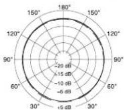
radar
| Angle (°) | Value (dB) | |---|---| | 0 | -20 | | 30 | -15 | | 60 | -10 | | 90 | -6 | | 120 | -15 | | 150 | -20 | | 180 | -15 | | 210 | -10 | | 240 | -6 |250 Hz
- - - - 500 Hz
——1000 Hz
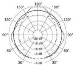
radar
| Angle | Value | |---|---| | 0° | -20 dB | | 30° | -15 dB | | 60° | -10 dB | | 90° | -5 dB | | 120° | -10 dB | | 150° | -5 dB | | 180° | -10 dB | | 210° | -5 dB | | 240° | -10 dB | | 270° | -5 dB | | 300° | -10 dB | | 330° | -5 dB | | 360° | -10 dB |2600 Hz
- - - - 6400 Hz
——10000 Hz
OMNIDIRECTIONAL
NNELLE OMNIDIRECCIONAL
OMNIDIREZIONALE OMNIDIREZIONALE
ALLE RICHTUNGEN OMNIDIREZIONALE
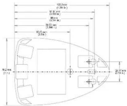
SHURE®
United States, Canada, Latin
America, Caribbean:
Shure Incorporated
5800 West Touhy Avenue
Niles, IL 60714-4608 USA
Phone: 847-600-2000
Fax: 847-600-1212 (USA)
Fax: 847-600-6446
Email: info@shure.com
www.shure.com
©2011 Shure Incorporated
Europe, Middle East, Africa:
Shure Europe GmbH
Jakob-Dieffenbacher-Str. 12,
75031 Eppingen, Germany
Phone: 49-7262-92490
Fax: 49-7262-9249114
22/F, 625 King's Road
North Point, Island East
Hong Kong
Phone: 852-2893-4290
Fax: 852-2893-4055
- MX300 Boundary Microphones
- Features
- Model Variations
- Interchangeable Cartridges
- Permanent Installation
- MX392 & MX393
- Microphone Placement
- Configuration
- DIP Switches
- Mute Button Configuration
- Connecting to an Automatic Mixer
- Logic Wiring
- Changing SWITCH OUT to Always Momentary
- Re-Routing Cable for Bottom Exit (MX392 Only)
- Painting
- Specifications
- Type
- Frequency Response
- Polar Pattern
- Output Impedance
- Output Configuration
- Sensitivity (at 1 kHz, open circuit voltage)
- Maximum SPL (1 kHz at 1% THD, 1 kΩ load)
- Equivalent Output Noise (A-weighted)
- Signal-to-Noise Ratio (referenced at 94 dB
- SPL at 1 kHz)
- Dynamic Range (1 kΩ load at 1 kHz)
- Common Mode Rejection (10 Hz to 100 kHz)
- Preamplifier Output Clipping Level (1% THD)
- Polarity
- Net Weight
- Packaged Weight
- Logic Connections
- Mute Switch Attenuation
- Cable
- Environmental Conditions
- Power Requirements
- Furnished Accessories
- Replacement Parts
- CERTIFICATION
- Bornes logiques
- Peinture
- Connexions logiques
- Mikrofonaufstellung
- Logikanschlüsse
- Conexiones lógicas
- Collegamenti logici
- MX300
- バウンダリーマ
- イクロホン
- マイクロホンの配置
- ミュートボタン設定
- ロジックコネクター
Brand : SHURE
Model : Microflex MX393
Category : Microphone