
H-HOOD 700 HDC110IN - Range hood HOOVER - Free user manual and instructions
Find the device manual for free H-HOOD 700 HDC110IN HOOVER in PDF.

| Product type | Wall-mounted extractor hood |
| Brand | Hoover |
| Model | H-HOOD 700 HDC110IN |
| Width | 70 cm |
| Depth | 50 cm |
| Height (min - max) | 50 - 100 cm |
| Net weight | 8.5 kg |
| Power supply | 220-240 V ~ 50 Hz |
| Motor power | 200 W |
| Max airflow | 600 m³/h |
| Noise level | 55 dB(A) |
| Energy class | A |
| Control type | Touch electronic |
| Lighting | LED, 1.5 W |
| Grease filter | Aluminium, dishwasher safe |
| Charcoal filter (optional) | Yes, rechargeable |
| Functions | Extraction or recirculation, 3 speeds + intensive |
| Maintenance | Clean the grease filters every month |
| Safety | Automatic shut-off, anti-backflow protection |
| Spare parts | Available via Hoover after-sales service |
| Repairability | Repairability index: 7.5/10 |
| Warranty | 2 years |
Frequently Asked Questions - H-HOOD 700 HDC110IN HOOVER
User questions about H-HOOD 700 HDC110IN HOOVER
0 question about this device. Answer the ones you know or ask your own.
Ask a new question about this device
Download the instructions for your Range hood in PDF format for free! Find your manual H-HOOD 700 HDC110IN - HOOVER and take your electronic device back in hand. On this page are published all the documents necessary for the use of your device. H-HOOD 700 HDC110IN by HOOVER.
USER MANUAL H-HOOD 700 HDC110IN HOOVER
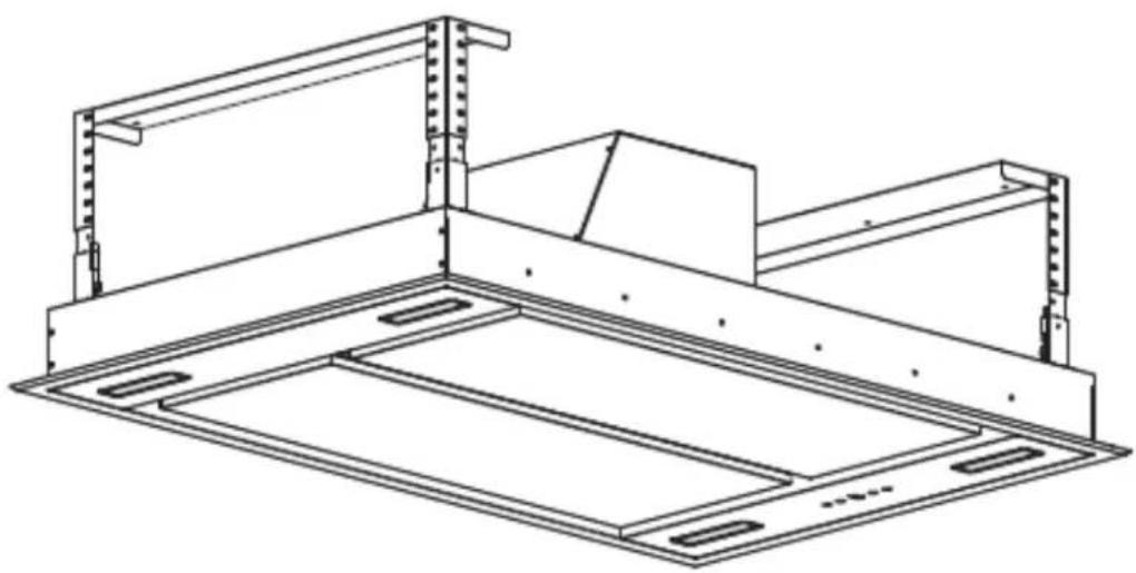
natural_image
Technical line drawing of a structural frame assembly (no text or symbols)ENGLISH(EN)----page 001
GERMAN(DE)----page 019
FRENCH(FR)----page 039
DUTCH(NL)----page 059
PORTUGUESE(PT)----page 079
CECO(CZ)----page 100
ITALIANO (IT)----page 120
POLISH (PL) --page 141
SLOVAK (SK)----page 160
Instruction Manual
natural_image
Technical line drawing of a structural frame assembly (no text or symbols)This Installation manual only applicable to Detachable ceiling decorative board
WARNING
This appliance can be used by children aged from 8 years and above and persons with reduced physical, sensory or mental capabilities or lack of experience and knowledge if they have been given supervision or instruction concerning use of the appliance in a safe way and understand the hazards involved. Children shall not play with the appliance. Cleaning and user maintenance shall not be made by children without supervision
If the supply cord is damaged, it must be replaced by the manufacturer, its service agent or similarly qualified persons in order to avoid a hazard.
The instructions shall state the substance of the following:
– there shall be adequate ventilation of the room when the range hood is used at the same time as appliances burning gas or other fuels (not applicable to appliances that only discharge the air back into the room);
– the details concerning the method and frequency of cleaning;
– there is a fire risk if cleaning is not carried out in accordance with the instructions;
– do not flambé under the range hood;
- CAUTION: Accessible parts may become hot when used with cooking appliances.
The installation instructions shall include the substance of the following:
– the air must not be discharged into a flue that is used for exhausting fumes from appliances burning gas or other fuels (not applicable to appliances that only discharge the air back into the room);
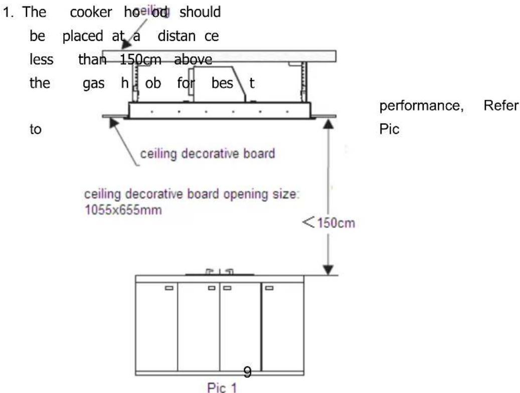
- the minimum distance between the supporting surface for the cooking vessels on the hob and the lowest part of the range hood. (When the range hood is located above a gas appliance, this distance shall be at least 65 cm.
– regulations concerning the discharge of air have to be fulfilled.
The installation instructions for range hoods with accessible metallic enclosures of class II construction shall include details that indicate the location and maximum permitted lengths for any fixing or mounting screw or other fixing device that penetrates into the range hood to attach an accessory such as a facia or duct fitting.
Where fixing or mounting screws, or other fixing devices are used, that penetrate into the range hood with an accessible metallic enclosure of class II construction, to attach an accessory, the instructions shall indicate the required location of these screws or fixing devices and include the substance of the following warning.
Warning: Failure to install the screws or fixing device in accordance with these instructions may result in electrical hazards
With this the Candy Hoover Group, declares that this appliance marked with complies with the essential requirements of the Directive 2014/53/EU.
To receive a copy of the declaration of conformity, please contact the manufacturer at: www.candy-group.com.
SAFETY PRECAUTION
Keep children away from the product when it is operating and do not allow them to play with or near the product.
The cooer hood is for domestic use only, not suitable for barbecue, roast shop and other commercial use.
All installat ion work must be carried out by a competent person or qualified electrician
The cooker hood and its filter mesh should be cleaned regularly in order to keep in good working order.
The cooker hood must be disconnected to from the power supply before cleaning procedures
Clean the cooker hood according to the instruction manual to avoid the risk of electric shock or product damage.
Do not light up any fire directly under the cooker hood.
If there is any fault with your cooker hood, please call the service department immediately
Please ensure there is enough ventilation when you are using the cooker hood and hob at the same times.
Do not connect the ducting system of the cook-er hood to existing ventilation system which it is being use for gas hob or other fuel burning appliance.
Make sure that the voltage (V) and d wattage (W) shown on the cooker hood label are same as the local require before installation and use.
To ensure the cooker hood perform in perfect condition, please read the instruction manual c arefully be fore in stallation and usag e, keep it in a right place
In order get our best service on cooker hood, Please keep the maintenance card and invoice. Othe rwise, the warrant y service will be void.
◇
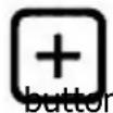
Controls
Several button on the controls panel which perform different function separately (refer to photo 1)
When you initially connect your hood to the electrical supply. The LCD display backlight will turn on. The backlight will be turn off after 30 seconds if no buttons are pressed.
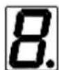


Photo 1
Light control

- Press the light button once to turn the cooker hood light on. Press the light button again to turn the cooker hood light off. The lighting button it is controlled separately and will not affect any other functions.
Power control

- Press the power button once, power indicator light on and the cooker hood run at Medium 2 speed, with moto speed button and lighting button light on. Press the Power button again, the cooker hood will be power off and the indicator light off together, the cooker hood in standby mode.
Speed increasing selection

- The speed function totally with 4 speed selection. Low, Medium2, Medium1, High speed. The speed symbol will appear from LCD display as: "1", "2", "3", "4".

- Press the button, the indicator light on. The motor run at low speed."1" will appear on LCD display.
- When the motor run at low speed, you may press the button shift motor speed to medium2, "2" speed symbol will appear on LCD display.

- When the motor run at medium2 speed, you may press the button shift motor speed to medium1, "3" speed symbol will appear on LCD display.

When the motor run at medium1 speed, you may press the button shift motor speed to high, "4" speed symbol will appear on LCD display.
When the motor run at high speed, press the working at high speed mode.

button, the motor keep
- When the hood on shift working, the motor speed run at High and Medium1 speed cumulative work for 7 minutes it will automatically shift to speed medium2.
Speed decreasing selection


- Press the button once, the speed level will be decreased to a lower

one, the speed level no. will appear on LCD display. Press there repeated till the speed level to "0", the cooker hood will be switch off and the indicator light off together.
Timer control

- When the cooker hood in working mode, included motor speed run and light turn on, you are able to setting the timer.
Before setting the timer, keep the hoods at the speed you would like it be, press the timer button. Timer delay for 5 minutes, "5" appear on LCD display. The no. will be decrease to "4,3,2" in every minute. When "0" appear on the display, the power will be shut off. Motor stop working and the lighting will be turn off at the same time.
• After setting the timer, the timer will recalculate if the motor speed shifted.
Connecting the remote control
• A New remote control has to establish a new connection to the cooker hood when used for first time. One remote control could possibly control several cooker hoods at the same time.
Connection process between remote control and cooker hood

- Press for 5 seconds within 15 seconds of cooker hood plug in, the indicators light begin flashing, the cooker hood is in connection mode, press any bottom on remote control to confirm the connection. The connection process finished and the remote control can be used for speed selection, lighting and timer setting.
‘If you want to connect again, you will need to clear the code that has been set up previously.
• To clear the code, press

for 5 seconds, the indicators light begin
flashing, the cooker is in connection mode. Then, press seconds, the previous connection code is cleared.

again for 5
- When the previous code has been cleared, the cooker hood back to standby

mode, press for 5 seconds, the indicate light flashing from one button to another, the cooker hood it in connection mode, then, press any bottom on remote control to confirm the connection.
- The remote control can set up the turning on/ increasing motor speed, turning off/Decreasing motor speed, timer on/off and light on/off functions.
Remote control
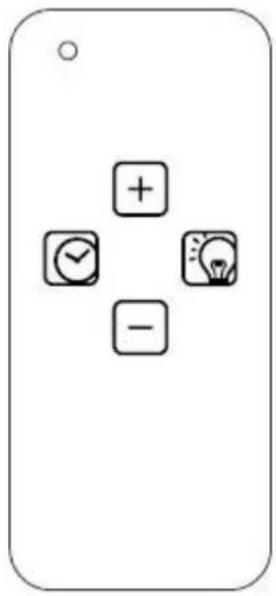
Lighting

Press button once, the light is on, press again, the light is off. The lighting button it is controlled separately and will not affect any other functions.
Turning on/ Increasing motor speed

1^st press, Low speed
2^nd press, Medium 2 speed
3^rd press Medium 1 speed
4^th press High speed
- When the hood on shift working, the motor speed run at High and Medium1 speed cumulative work for 7 minutes it will automatically shift to speed medium2.
Turning off/ Decreasing motor speed

Press the button and the motor begins shift to a lower speed and the LCD screen display the speed level. Repeating press the button, it keeps on decreasing the motor speed to till the cooker hood turning off.
Timer

Press the button to set up the timer on/off function.
- When the cooker hood in working mode, included motor speed run and light turn on, you are able to setting the timer. Set timer delay for 5 minutes. After 5 minutes, the power will be shut off. Motor stop working and the lighting will be turn off at the same time.
·After setting the timer, the timer will recalculate if the motor speed shifted.
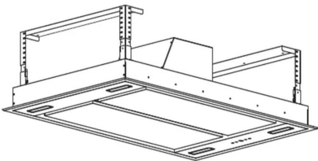
Installation
-
The ceiling should be able to bear at least 120KG in weights and the thickness must more than 30mm.
-
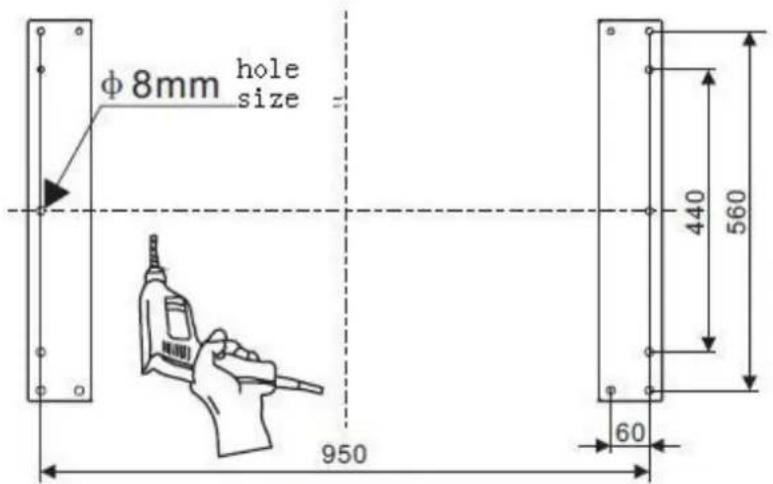
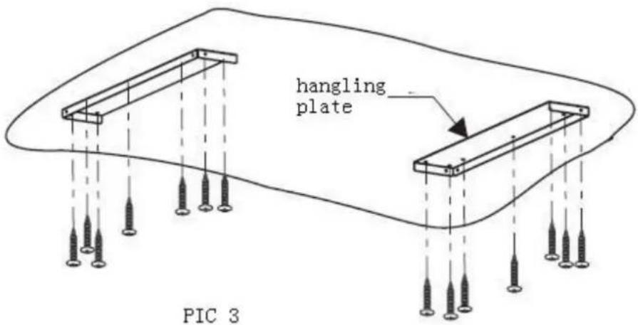
Positon the hanging plate on the ceiling and then mark the position of screw holes(refer to pic 2). Drill 14 pcs holes at diame ter 8mm on the ceiling and 2pcs of han ging plate should be se curely fixted to ceiling by using 14pcs expansion screws( or 14pcs ST6 x40MM tappi ng screws and wall plugs). Refer pic 3
Pic 2
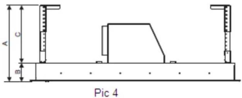
- Calculate t he length of angle bar(refer to pic 4/5), adjust the corner connector bar to the r required height, then fix t hem with angle bar u sing the 10mm x M4 nut and b olts with metal washer (32pcs), the angle bar must have an overlap of at least 36mm.
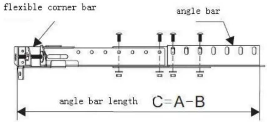
Pic 5
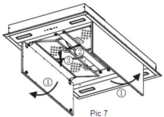
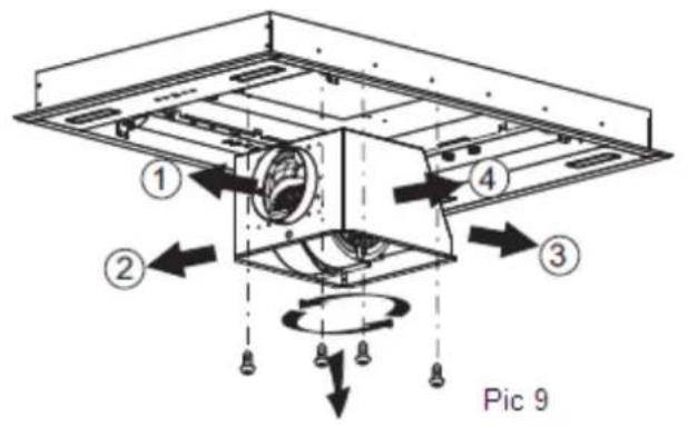
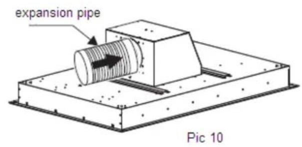
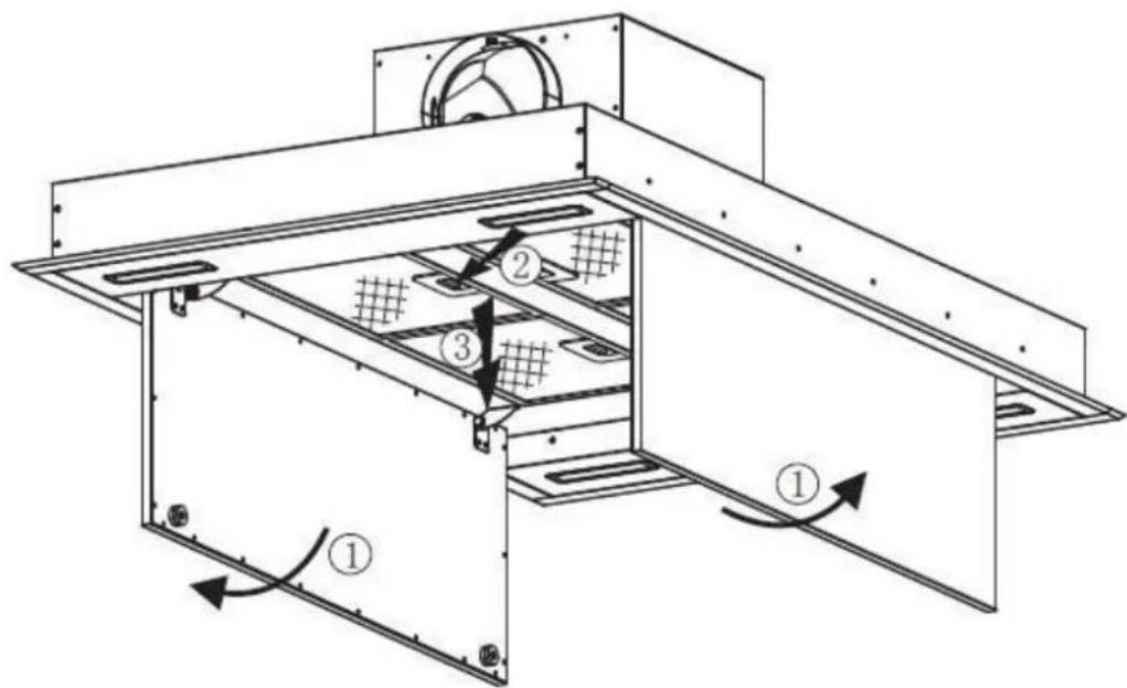
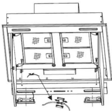
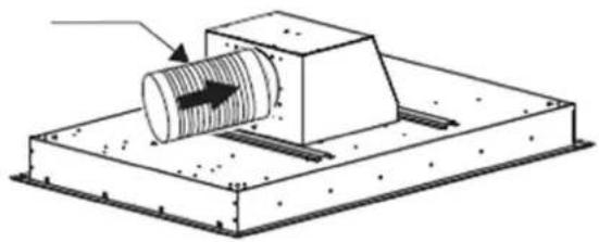
- As pic 9 shown, choose the direction of the outlet①/②/③/④
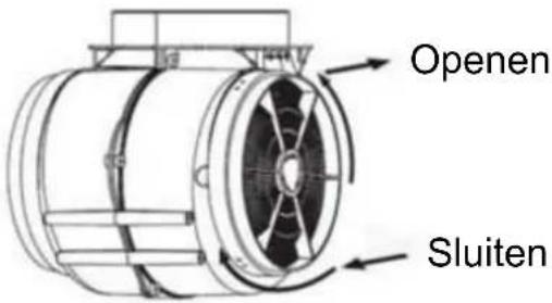
a. Refer to Pic 7, open the decorative plate in order, and take out the filter.
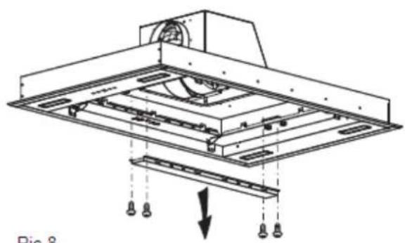
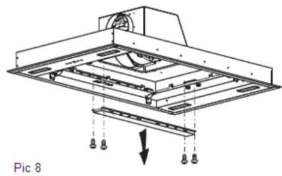
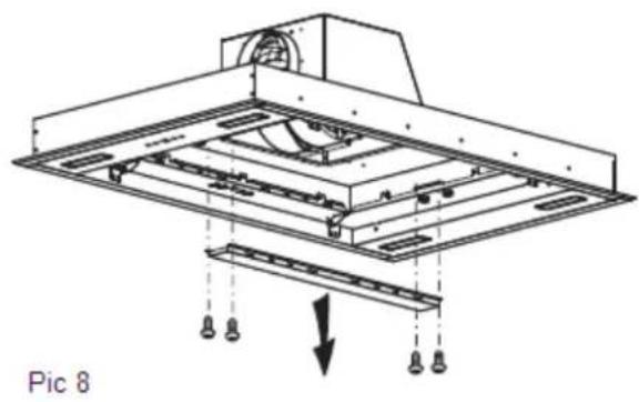
b. Refer to Pic 8, unscrew and take away the 4 pcs ST4*8mm screws that on the panel decorative strip.
c. Unscrew the 8pcs machine silk from the bottom of the cabinet housing and rotate it by 90^ / 180^ / 270^ to choose the direction of the outlet, then screw the 8 pcs machine silk to fix the housing well;
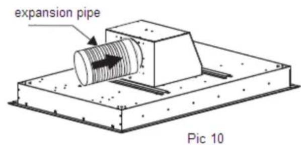
d. Install the panel decorative strip and filter well apply to the reverse order of a/b steps above, meanwhile, install the expansion pipe to the outlet (refer to pic 10).
natural_image
Technical diagram of a mechanical assembly with hanging components and a downward arrow indicating motion (no text or symbols)Pic 8
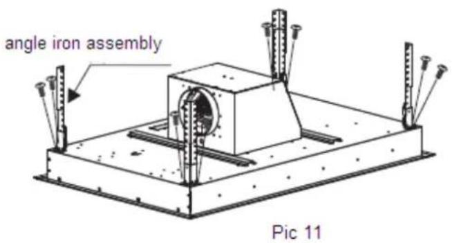
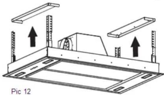
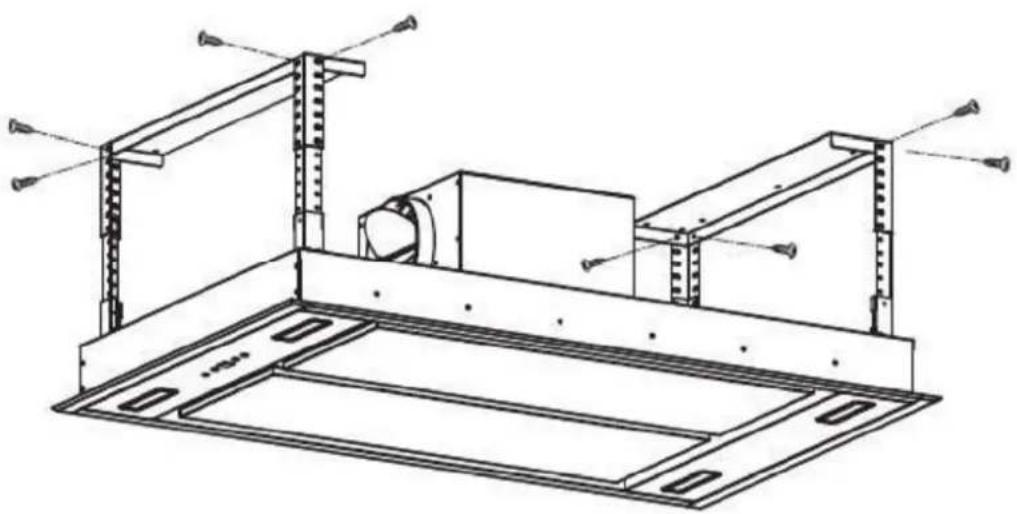
- Use M4X 10MM screws(8pcs) to fix the corner connector bar (4pcs) onto the main body of the cooker hood. Refer pic 11&pic 12.
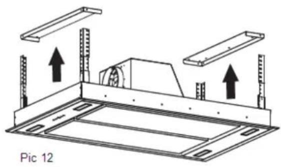
natural_image
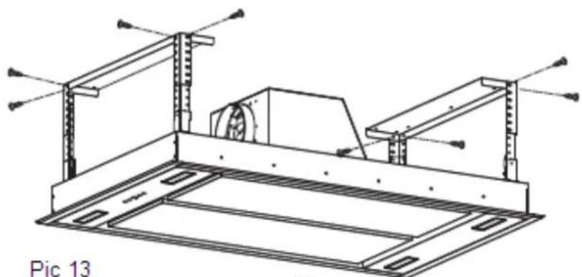
Technical diagram of a mechanical assembly with two plates and mounting brackets, labeled 'Pic 12' (no text or symbols on the diagram itself)Lift the main body of the cooker hood toward the hanging plate, use M4 x 12mm bolts and nut with metal washer (8pcs) to attach the angle bar to the hanging plate(2pcs). the ducting hose should be connected to your external ducting at this stage. Refer to pic 12/13
Important: 1. the ducting hose must be securely fixed onto the body of the cooker hood. 2. All the he screws must be fully tightened.
natural_image
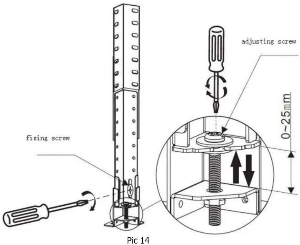
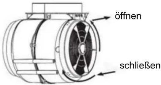
Technical line drawing of a mechanical assembly with supports and a central component (no text or symbols)- When the main body of the cooker hood is fixed on the hanging plate, if you want to set the body of the cooker hood in hori zontal position and a djust it to the required height , you may use straight or cross screwdriver to adjust the screw on the fl exible corner. The detail setting meth od refer to pic 14, adjust th e s crew on each flexibl e corner by using g th e screw driver towards clockwise di rection, the body of the cooker hood will move up to hanging plate. When you a djust th e screw on each fl exible corner by using the screwdriver towards anticlockwise direct ion, the body of the co oker hood will move down to the floo r. The body of the cook er hood in horizontal position and d required height ar e well f ixed. Use th e cross sc rewdriver tighten the fixing screw on the flexible corner.
Care and Cleaning
Removing the clean the grease filters
-
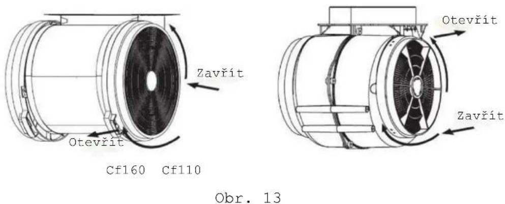
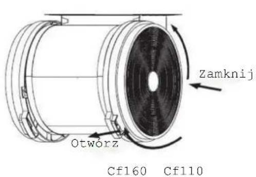
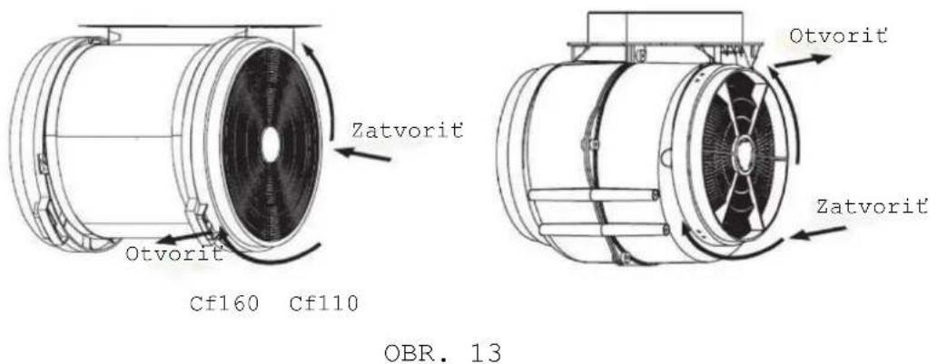
Remove the grease filters of the cook hood should following the cleaning procedure as pic 13 shown.
-
Cleaning the grease filter you may refer to following method:
A. Sock the grease filter in 40°-50°warm water and washing up liquid for about 2 -3 minutes. Then use a soft brush to lo osen a ny gr ease deposits have formed. Wash it in a soft way, otherwise the filter will be damage.
B. You may use the dish washer to clean the grease filter. Put the filters into the dishwasher with washing up liquid. Set the temperature of 50^
C for water in t he dishwasher. And t hen turn on the switch for washing function.
C. All the grease filters are made by metal, never use the corrosion cleaning liquid for washing the grease filter.
Important: Before cleaning, always ensure that you have shut of the power supply of the cooker hood.
Fix the carbon filter into the cooker hood, installation and disassemble please refer to pic 13
PIC 13
Cf110
BULB REPLACEMENT
Important : | ✧ The bulb must be replaced by the manufacturer, its servi ce agent or similarly qualified persons.✧ Always switch off the electricity supply before carrying out any operations on the appliance. When handling bulb, make sure it is completely cool down before any direct contact to hands.✧ When handling gl obes hol d with a cloth or gloves to ensure perspiration does not come in contact with the gl obe as this can reduce the life of the globe. |
Changing a lamp bulb for LED
Use the screw driver loosen the ST4*8MM self tapping screw (2pcs) from the lighting panel, ta ke out t he lighting fixture. Open the terminal box that connected with the wire, disconnect the wire connector and replace the lamp.
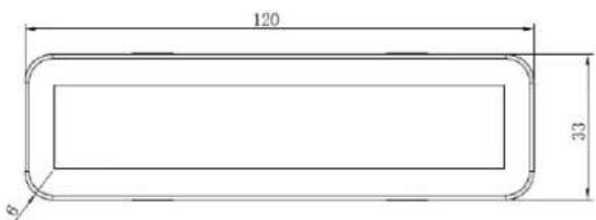
- ILCOS D code for this lamp is: DBS-2.5/65-H-120/33
- LED modules -rectangle lamp
- Max wattage: 2.5 W
– Voltage range: AC 220-240V - Dimensions:
natural_image
Technical line drawing of a mechanical or electronic device with internal compartments and mounting points (no text or symbols)RC remote controller-radio equipment intentionally emitting radio waves.
| Parameter | Specifications |
| Wireless Standard | ETSI EN 300 220-2 V3.1.1 |
| Frequency Range | 433.92 MHz ± 50 kHz |
| Max Trasmit Power | -27.21dbm |
| Minimum Receiving Sensitivity | / |
| Channel | 1 |
ENVIRONMENTAL PROTECTION:
This product is marked according to the European Directive 2012/19/EU on Waste Electrical and Electronic Equipment (WEEE).
WEEE contains both polluting substances (which can cause negative consequences for the environment) and basic components (which can be re-used). It is important to have WEEE subjected to specific treatments, in order to remove and dispose properly all pollutants, and recover and recycle other materials.
WEEE shall not be treated as household waste. For more information, please contact your local or regional authorities.
Note :
a. In order to reduce the environmental impact (e.g. energy use) of the cooking process, please be sure that your product is installed according to the user manual, keep the operation place ventilated, keep the
extraction duct be direct and short as possible as it can be.
b. For the product with manual operation mode, we suggest switch the motor off within 10 minutes after finishing the cooking process.
c. Please be sure to dismantle related components according to the user manual when maintaining for non-destructive, protect the parts to make the re-installed work can be favoring and avoid damage.
By placing the CE ( ) marking on this product, we declare, on our own responsibility, compliance to all of European safety, health and environmental requirements stated in the legislation for this product.
Bedienungshandbuch
natural_image
Technical line drawing of a structural frame assembly (no text or symbols)Beleuchtung

natural_image
Technical line drawing of a mechanical assembly with supports and a central component (no text or symbols)Abb. 13
ABB. 15
natural_image
Technical line drawing of an internal rack or storage unit with multiple compartments and mounting hardware (no text or symbols)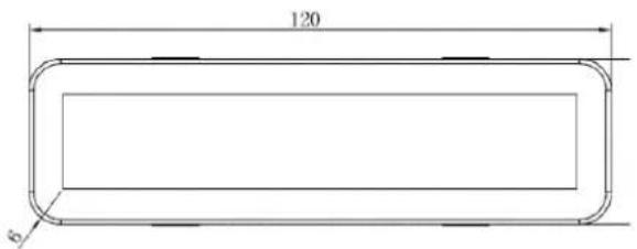
natural_image
Technical line drawing of a structural frame assembly (no text or symbols)Éclairage

natural_image
Technical line drawing of a mechanical assembly with supports and a central component (no text or symbols)Fig. 13
Fig. 15
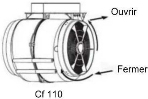
Fig. 15
REEMPLACEMENT D'UNE LAMPE
Important :

natural_image
Technical line drawing of a rack-mounted device with internal compartments and mounting hardware (no text or symbols)natural_image
Technical line drawing of a structural frame assembly (no text or symbols)Verlichting

natural_image
Technical diagram of a mechanical assembly with labeled components and downward force arrow (no text or symbols beyond label)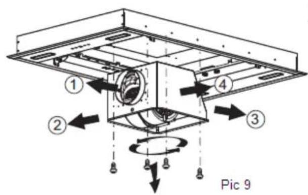
Expansiepijp
natural_image
Technical diagram of a mechanical assembly with a cylindrical component and mounting base (no text or symbols)natural_image
Technical diagram of a structural frame with two horizontal plates and vertical supports, showing upward force arrows (no text or symbols)Afb. 12
natural_image
Technical line drawing of a mechanical assembly with supports and a central component (no text or symbols)AFB. 13
AFB.
Cf 110
AFB. 15
LAMP VERVANGEN
Belangrijk:

natural_image
Technical line drawing of a multi-chamber electronic device with no visible text or symbolsnatural_image
Technical line drawing of a structural frame assembly (no text or symbols)Índice
natural_image
Diagram of airflow around a mechanical component with directional arrows indicating movement (no text or symbols)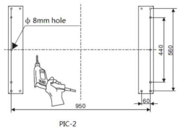
PIC-5
natural_image
Technical diagram of a mechanical assembly with labeled components and directional arrows (no readable text or symbols)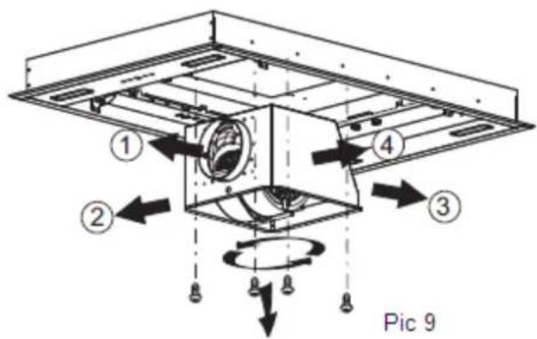
Pic 11
natural_image
Technical diagram of a mechanical assembly with two metal plates and mounting brackets, no text or symbols present
natural_image
Technical line drawing of a mechanical assembly with supports and a central component (no text or symbols)Pic 14
Iluminação

natural_image
Abstract line drawing of a stylized animal figure with a circular head and arrow, no text or symbols present.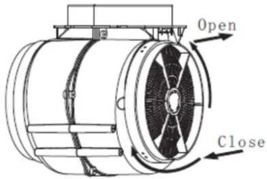
Cf110
NOTA:
natural_image
Technical line drawing of an open server rack with internal compartments and connectors (no text or symbols)RC remote controller-radio equipment intentionally emitting radio waves
| Parameter | Specifications |
| Wireless Standard | ETSI EN 300 220-2 V3.1.1 |
| Frequency Range | 433.92 MHz ± 50 kHz |
| Max Trasmit Power | -27.21dbm |
| Minimum Receiving Sensitivity | / |
| Channel | 1 |
natural_image
Technical line drawing of a structural frame assembly (no text or symbols)Osvětlení
natural_image
Technical line drawing of a mechanical assembly with two vertical supports and a central component, no text or symbols present.Obr. 10

natural_image
Technical line drawing of a structural frame assembly with mounting brackets and support beams (no text or symbols)Obr. 11
Obr. 13
Výměna žárovky
natural_image
Technical line drawing of a mechanical assembly with mounting brackets and a tool (no text or symbols)Obr. 15
natural_image
Technical line drawing of a ceiling structure with mounting bracket and hanging fixture (no text or symbols)Obr. 16
natural_image
Technical line drawing of a server rack with internal compartments and cable connections (no text or symbols)Obr. 17
OCHRANA ŽIVOTNÍHO PROSTŘEDÍ
natural_image
Technical line drawing of a structural frame assembly (no text or symbols)Illuminazione
natural_image
Technical line drawing of a mechanical assembly with two vertical supports and an internal component, no text or symbols present.Figura 10
natural_image
Technical line drawing of a mechanical assembly with mounting brackets and structural supports (no text or symbols)Figura 11
Figura 13
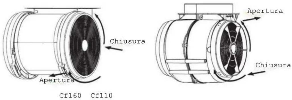
Figura 13
natural_image
Technical line drawing of a ceiling-mounted device with a tool and base plate (no text or symbols)Figura 15
natural_image
Technical line drawing of a ceiling structure with mounting bracket and hanging fixture (no text or symbols)Figura 16
natural_image
Technical line drawing of a server rack with internal compartments and cable connections (no text or symbols)Figura 17
natural_image
Technical line drawing of a structural frame assembly (no text or symbols)Oświetlenie
natural_image
Technical line drawing of a mechanical assembly with two vertical supports and an internal component, no text or symbols present.RYS. 10

natural_image
Technical line drawing of a mechanical assembly with mounting brackets and structural supports (no text or symbols)RYS. 11
RYS. 13
natural_image
Technical line drawing of a ceiling structure with mounting brackets and a tool, no text or symbols presentRYS. 15
natural_image
Technical line drawing of a ceiling structure with mounting bracket and hanging fixture (no text or symbols)RYS. 16
natural_image
Technical line drawing of an internal rack-mounted device with multiple compartments and connectors (no text or symbols)OCHRONA ŚRODOWISKA:
natural_image
Technical line drawing of a structural frame assembly (no text or symbols)Osvetlenie
Obr. 5
natural_image
Technical line drawing of a mechanical assembly with two vertical supports and an internal component, no text or symbols present.OBR. 10

natural_image
Technical line drawing of a mechanical assembly with mounting brackets and structural supports (no text or symbols)OBR. 11
OBR. 13
natural_image
Technical line drawing of a mechanical assembly with a tool and base plate (no text or symbols)OBR. 15
natural_image
Technical line drawing of a ceiling structure with mounting bracket and hanging fixture (no text or symbols)OBR. 16
natural_image
Technical line drawing of a server rack with multiple drive bays and cable connectors (no text or labels)OCHRANA ŽIVOTNÉHO PROSTREDIA:

- Instruction Manual
- WARNING
- SAFETY PRECAUTION
- Controls
- Light control
- Power control
- Speed increasing selection
- Speed decreasing selection
- Timer control
- Connecting the remote control
- Remote control
- Lighting
- Turning on/ Increasing motor speed
- Turning off/ Decreasing motor speed
- Timer
- Installation
- Care and Cleaning
- BULB REPLACEMENT
- Changing a lamp bulb for LED
- ENVIRONMENTAL PROTECTION:
- Note :
- Bedienungshandbuch
- Beleuchtung
- Éclairage
- REEMPLACEMENT D'UNE LAMPE
- Verlichting
- LAMP VERVANGEN
- Índice
- Iluminação
- NOTA:
- Osvětlení
- Výměna žárovky
- OCHRANA ŽIVOTNÍHO PROSTŘEDÍ
- Illuminazione
- Oświetlenie
- OCHRONA ŚRODOWISKA:
- Osvetlenie
- OCHRANA ŽIVOTNÉHO PROSTREDIA:
Brand : HOOVER
Model : H-HOOD 700 HDC110IN
Category : Range hood