
DU 668 G - Range hood BOMANN - Free user manual and instructions
Find the device manual for free DU 668 G BOMANN in PDF.


| Product Type | Range Hood |
| Brand | Bomann |
| Model | DU 668 G |
| Dimensions (H x W x D) | 39.0 x 60.0 x 40.5 cm |
| Duct Dimensions (H x W x D) | 71.0 – 95.0 x 30.2 x 26.7 cm |
| Net Weight | Approx. 19.0 kg |
| Power Supply | 230 V ~ 50 Hz |
| Rated Power | 191 W |
| Lighting | 2 x 0.5 W LED |
| Protection Class | I |
| Fan Speeds | 3 (low, medium, high) |
| Airflow (min) | 380.2 m³/h |
| Airflow (max) | 585.7 m³/h |
| Sound Level (min/max) | 63 dB / 69 dB |
| Energy Efficiency Class | C |
| Grease Filtering Efficiency Class | F |
| Lighting Efficiency Class | A |
| Operation Modes | Extraction and Recirculation |
| Duct Diameter | 150 mm |
| Grease Filter | Aluminum, washable (monthly) |
| Activated Carbon Filter | Optional (not included), replace every 6 months |
| Minimum Safety Distance (electric hob) | 45–55 cm |
| Minimum Safety Distance (gas hob) | At least 65 cm |
| Glass Capture Panel Width | 60 cm |
| Included Accessories | Telescopic duct, non-return valves, mounting kit |
Frequently Asked Questions - DU 668 G BOMANN
User questions about DU 668 G BOMANN
0 question about this device. Answer the ones you know or ask your own.
Ask a new question about this device
Download the instructions for your Range hood in PDF format for free! Find your manual DU 668 G - BOMANN and take your electronic device back in hand. On this page are published all the documents necessary for the use of your device. DU 668 G by BOMANN.
USER MANUAL DU 668 G BOMANN
natural_image
Modern stainless steel kitchen air purifier with open doors and ventilation grilles (no visible text or symbols)Special safety Information for this Unit....Page 17
Unpacking the Appliance......Page 18
Overview of the Appliance....Page 18
Installation......Page 18
Startup / Operation......Page 21
Cleaning and Maintenance......Page 22
Repairs....Page 23
Troubleshooting......Page 24
Technical Data....Page 24
natural_image
Architectural cross-section diagram showing brick wall and insulation layers with a magnified inset (no text or symbols)natural_image
Simple line drawing of a mechanical setup with three plates and four bolts (no text or symbols)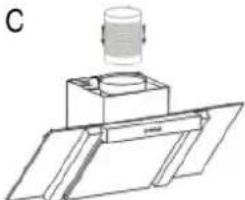
natural_image
Technical line drawing of a mechanical assembly with a cylindrical component mounted on a base plate (no text or symbols)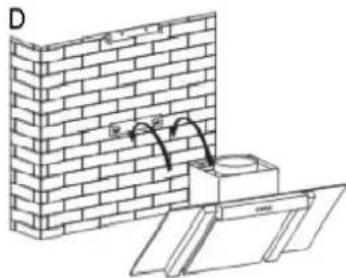
natural_image
Diagram showing brick wall and support structure with a pipe or pipe connection (no text or symbols)natural_image
Simple line drawing of a 3D rectangular prism with internal structure and labeled points (no text or symbols)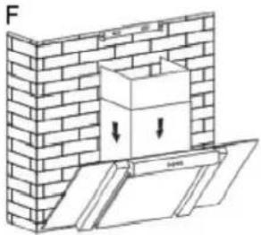
natural_image
Diagram of a brick wall with a box and directional arrows indicating movement or force (no text or symbols)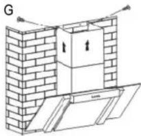
natural_image
Architectural diagram of a brick wall with a cabinet and support structure (no text or symbols)Thank you for choosing our product. We hope you will enjoy using the appliance.
Symbols in these Instructions for Use
Important information for your safety is specially marked. It is essential to comply with these instructions in order to avoid accidents and prevent damage to the machine:

WARNING
This warns you of dangers to your health and indicates possible injury risks.

CAUTION:CAUTION
This refers to possible hazards to the machine or other objects.

NOTENDIT highlights tips and information.
General Notes General Notes
Read the operating instructions carefully before putting the appliance into operation and keep the instructions and the receipt. If you give this appliance to other people, please also pass on the operating instructions.
- The appliance is designed exclusively for private use and for the envisaged purpose. This appliance is not fit for commercial use.
- The appliance is only to be used as described in the user manual. Do not use the appliance for any other purpose. Any other use is not intended and can result in damages or personal injuries.
- Operate the appliance only properly installed.
- Do not use it outdoors. Keep it away from sources of heat, direct sunlight and humidity. Do not use the appliance with wet hands.
- Do not operate the machine without supervision.
- When not in use, for cleaning, user maintenance works or with disruption, switch off the appliance and if possibly disconnect the plug (pull the plug itself, not the lead) or turn off the fuse.
- The appliance and if possibly the mains lead have to be checked regularly for signs of damage. If damage is found the appliance must not be used.
- For safety reasons, alterations or modifications of the appliance are prohibited.
- In order to ensure your children's safety, please keep all packaging (plastic bags, boxes, polystyrene etc.) out of their reach.

WARNING: WARNING:
Do not allow small children to play with the foil. There is a danger of suffocation!
Special safety Information for this Uspecial safety Information fo
- Provision shall be made for adequate ventilation in the room when the cooker hood is operated simultaneously with appliances that burn gas or other fuels.
- Attention! Attractable parts of the appliance may become hot when used with cooking utensils.
- Do not flambé under the cooker hood! You can fry under the hood due to fire hazard only under constant observation.
- Open the gas supply at gas stoves only when cookware is on the stove. Risk of Risk of fireIfThe filter can be damaged.
- Food during frying should be constantly supervised. By overheated oil can arise a fire hazardfire hazard
- Do not check the filter condition while the hood is in operation.
- NEVER use the appliance without fixed aluminum grease filter.
- If the cooker hood and other devices which are powered b other forms of energy as electricity, served together, the pressure in the room should not exceed 4 Pa ( 4 × 10^-5 bar).
- Regulations concerning the discharge of air have to be fulfilled.
- Follow the installation instructions. Note the instructions that we give you in the chapter "Installation".
- This appliance can be used by children and guide from 8 years and above and persons with reduced physical, sensory or mental capabilities or lack of experience and knowledge if they have been given supervision or instruction concerning use of use of the appliance in a safe way and understand the hazards involved.
- ChildrenChildrent play with the appliance.
- Cleaning and user maintenance must maintain a trade by children, while they are older 8 years and supervised.
- The appliance must be cleaned regularly. Follow the instructions that we give you in the chapter “Cleaning and Maintenance”. There is a risk of fire if cleaning is not carried out according to these instructions.
- Do not try to repair the appliance on your own. Always contact an authorized technician. To avoid the exposure to danger, always have faulty cable be replaced only by the manufacturer, by our customer service or by qualified person and with a cable of the same type.
Unpacking the Appliance Unpacking the Appliance
- Remove the appliance from its packaging.
- Remove all packaging material, such as foils, filler, cable holder and cardboard packaging.
- To prevent hazards, check the appliance for any transport damage.
- In case of damage, do not put the appliance into operation. Contact your distributor.
i NOTENOTE
Production residue or dust may have collected on the appliance. We recommend cleaning the appliance according to chapter "Cleaning and Maintenance".
Overview of the Appliance Overview of the Appliance
i NOTENOTEoriginal appliance may differ from the appliance pictured here.
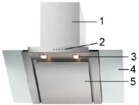
| 1 | Telescopic duct, 2-part |
| 2 | Control panel |
| 3 | Lighting |
| 4 | Glass capture panel |
| 5 | Aluminum grease filter cover |
Supplied parts Supplied parts
1 x glass capture panel
1 x outer (lower) duct without ventilation slots
2 x non-return valve
1 x inner (upper) duct with ventilation
slots
Assembly material incl. drill template
Installation
There must be a safety distance between the hotplate of the cooking pot on the hob and the bottom part of the extractor hood:
The distance must be between 45 The 55 distance of gas appliances, 45 the distance must be at least 65 cm. If the installation instructions for the gas cooker specify a greater distance, this distance must be taken into consideration.
Selecting the fume outletSelecting the fume outlet
You can operate the extractor hood in two modes:
Extraction mode Extraction mode
WARNING: WARNING:
- The extracted air may not be vented into a flue which is used for the waste gas from appliances which are powered by gas or other fuels.
- When venting the extracted air, comply with the regulations of the relevant local authorities.
The hood has an upper air outlet to vent cooking odours to the outside.
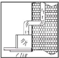
- The extracted air is normally vented vertically. If there is a suitable loft space above your kitch-
en, the extracted air is vented through the wall units and the loft floor to the roof ridge.

natural_image
Architectural cross-section diagram showing brick wall and insulation layers with a magnified inset of insulation (no text or symbols)- If there is a conduit in your kitchen under the wall units, the extraction duct can be routed so that the extracted
air can be vented horizontally through the wall.
Recirculation mode Recirculation mode
If you do not have a direct extraction vent to the outside; the hood can also work in recirculation mode (i.e. without an extraction vent to the out side; the filtered air is released back into the room). In this case, two activated carbon filter as de scribed uncler "Installing the activated car bon filter for recirculation mode", must be used.
The activated carbon filter are not supplied. You can order the car bon filter from your dealer or in our online accessories shop, www.bomann.dewToorderusedthe reference number found under "Technical Data".
AssemblyAssembly
WARNING: WARNING:
- When assembling or inserting the extraction filter as well as the carbon filter, the appliance must not be connected to the mains.
- Failure to use the mounting fixtures may lead to a risk of electric shockrisk of electric shock
CAUTIONCAUTION
- Before mounting, check that the wall has sufficient load capacity to bear the extractor hood.
- When drilling the holes in the wall always make sure that no existing electrical cables or other objects are damaged.
• Make sure that the vents are clear of obstacles and are not covered.
i NOTENRecommendeds for preparation work
- When installing, ask another person to assist.
- Wear protective gloves to prevent injuries from any sharp edges.
| 1 | 2 | 3 | |||
 |  |  | |||
| 4 5 | 6 7 | 8 | |||
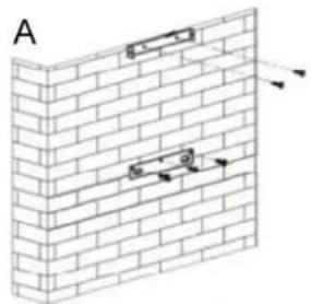
- Determine the position of the extractor hood centrally above the hob in conformance with the specified safety distances. - Mark the necessary holes for the wall mounting by using the supplied drill template and check them with a spirit level.
natural_image
Diagram of a brick wall with two embedded rectangular components and directional arrows indicating movement (no text or symbols)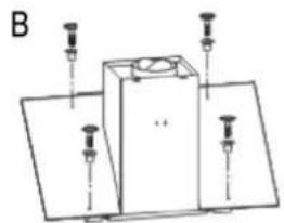
natural_image
Simple line drawing of a mechanical or electrical component with three vertical pins and a central box (no text or symbols)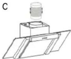
natural_image
Technical line drawing of a mechanical assembly with a cylindrical component mounted on a base plate (no text or symbols)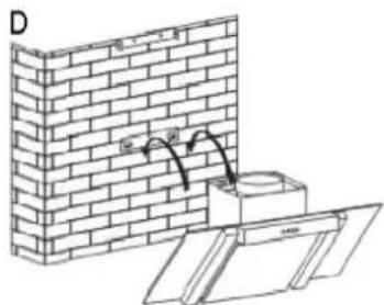
natural_image
Diagram of a brick wall corner with a pipe fitting and support structure, no text or symbols present- Drill ∅ 8 mm mounting holes into the wall for the respective brackets (1+2+3). Insert the dowel pins (5) and fasten the brackets with the screws (6).
-
Attach the suspension rail (1) for the hood body as well as the mounting rail with bracket (2) to the top edge parallel to the rail (1) (Fig. A). Determine the extension length of the duct cover in advance!
• Before suspending the hood: -
the glass capture panel is fastened to the hood body with the screws (7) in the rubber plugs with washers (Fig. B).
- insert the non-return valves (4) onto the extractor duct from above by gently bending them.
For extraction mode: For extraction mode:
- Hereupon a flexible extraction hose (not supplied) with an inner diameter of ∅ 150 mm must be attached (Fig. C) and connected to the outside by the extraction outlet.
- Hook the extractor hood into the suspension rail (1) (Fig. D). Check that it is secure and horizontally level.
natural_image
Simple line drawing of a cabinet or enclosure with no text, numbers, or symbols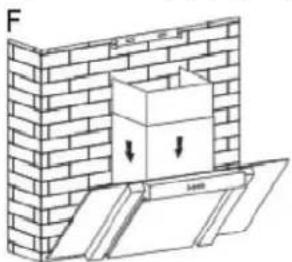
natural_image
Diagram of a brick wall with a box and directional arrows indicating movement or force (no text or symbols)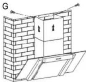
natural_image
Architectural diagram of a brick wall with an open door and ventilation duct (no text or symbols)- Remove the protective plastic from the telescopic duct.
-
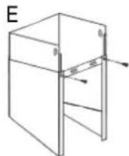
Fix the outer (lower) duct with the mounting rail without the bracket (3). The rail is fastened to the holes provided from the inside of the duct. Screw in two plate screws (8) from the back (Fig. E).
-
Place the outer duct with the fixed rail (3) onto the extractor hood (Fig. F). Fasten the rail (3) to the wall parallel to the other rails (1 + 2) .
- Slide the inner (upper) duct along the slide fixture into the outer (lower) duct. Make sure that the inner duct is aligned with the vents at the top. Determine the extension length of the duct cover by pulling up the inner duct or sliding back into the outer duct.
- For extraction mode, correctly position the flexible extraction hose (not supplied).
- Pull the inner duct cover up and fasten the duct unit on the side to the previously mounted rail (2) by screwing in the plate screws (8) (Fig. G).
Installing the activated carbon filling into the activation mode
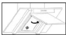
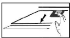
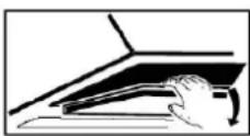
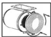
- Open the cover and remove the aluminum grease filter.
- Place the carbon filter onto the air intake of the extraction duct. Make sure that the mounting pins on the extraction duct engage the mounting slots of the carbon filter. Turn the respective filter clockwise until it clicks into place.
- Reinstall the alumin um grease filter and close the cover.
i NOTENOTE
The activated carbon filter absorbs odours and must be replaced at least every six months regardless of use.
Electrical connection Electrical connection
WARNING: WARNING:
- The installation to the mains supply must conform to the local standards and regulations.
- Improper connection may cause to an electric shock!
- Do not modify the appliance plug. If the plug does not fit properly to the outlet, let install a proper outlet by an authorized specialist.
- The accessibility of the power plug must be ensured in order to disconnect the appliance from the power supply in case of an emergency.
- Ensure that your mains power corresponds with the specifications of the appliance. The specifications are printed on the rating label.
- Connect the mains cable to a properly installed and earthed wall outlet.
Startup / Operation
The extractor hood is operated via pushbuttons. The individual fan settings as well as the lighting can be switched on and off with the corresponding buttons.
Lowest fan setting
Highest fan setting
The motor begins to run at low speed. This setting is suitable for cooking on a low flame and for dishes which produce no or little steam, in order to circulate the air around the kitchen.
Powerdecel:Power level:
The motor runs at moderate speed. This setting is suitable for normal cooking.
PowerdecelPower level
The motor runs at high speed. The setting is suitable if large quantities of smoke and steam need to be extracted or filtered (e.g. when frying).
i NOTENOTE
If a lot of vapour is produced, the fan should be left running for a few minutes after cooking. Only leave the fan running if absolutely necessary, since otherwise unnecessary energy is consumed.
Cleaning and Maintenance
The appliance and the operation there of are best maintained by regular cleaning of your extractor hood as well as the filter. The extractor hood and accessories should also be cleaned regularly for hygiene reasons.
WARNING: WARNING:
- Before cleaning or maintenance work, the device should always turn off and disconnect the mains plug or switch off the fuse.
- Allow the unit to cool down be fore cleaning.
- Do not uses steam cleaners for cleaning the device; moisture could enter electrical components. Risk of electric shock! electric shock should damage the plastic parts. The device must be dry before restarting operation.
CAUTION:CAUTION
- Do not use a wire brush or other sharp, abrasive items.
- Do not use any acidic or abrasive cleaners.
- To clean the surface of the housing, use a mild detergent and a soft cloth to prevent scratching.
- The appliance can be used again after everything has dried properly.
- If you use your ex tractor hood in recirculation mode, you must replace the activated carbon filter regularly (see "Replacing the activated carbon filter").
Cleaning the aluminum grease filter cumingrease filter
WARNING: Risk of fire!
Grease residues in the aluminum grease filter may ignite on exposure to high temperatures. It is therefore important that the grease filter is regularly cleaned / replaced.
Grease and vapours collect in the filter and may accumulate if not regularly cleaned. We recommend that you clean the grease filter monthly:
- Remove the aluminum grease filter by sliding back the lock in the handle recess, push the filter down gently and pull out towards the front.
- Rinse the grease filter in a solution of hot water and neutral detergent. Soak the grease filter in the solution.
- Then clean with a soft brush, rinse thoroughly with hot water and leave to dry.
- Alternatively, the grease filter can also be cleaned in the dishwasher (up to 60^ ). Slight discoloration may occur in the dishwasher. This does not affect the function of the grease filter.
Replacing the activated carbon filterReplacing the activated carbon filter
The activated carbon filter absorbs odours and must be replaced at least every six months, depending on use. Order the carbon filter from your dealer or in our online accessories shop, www.bomann.de. To order, use the reference number found under “Technical Data”.
- See "Installing the activated carbon filter for recirculation mode".
- Remove the old carbon filter by turning the filter anti-clockwise.
Replacing the lightingReplacing the lighting
WARNING: WARNING:
Allow the lamps to cool before replacing the lighting. Risk of burns!Risk of burns!
CAUTION:CAUTION:
Use only self shielded lamps in order to prevent excessive heating, fire hazards and exposure to UV radiation.
- Use the correct lighting: 22x00552W DED
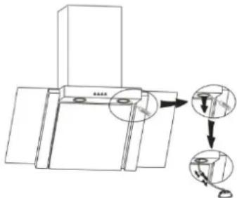
- Carefully remove the lamp with a suitable tool.
- Pull out the lamp carefully and disconnect the lamp from the connecting cable.
- Change the lamp.
- Connect the connecting cable to the lamp. Replace the lamp until it audibly clicks into the lamp socket.
RepairsRepairs
A wrong or improperly performed repair brings danger to the user.
Repairs to electrical appliances must only be carried out by an authorized specialist. A damaged power cord must be changed only by a qualified electrician.
TroubleshootingTroubleshooting
Before you contact an authorized specialist
The following problems can be solved by you by checking for the possible cause.
| ProblemPossible | Possible causePossible cause | SolutionSolution |
| The appliance is not working or does not work properly | - Is the unit not connected to mains power?- Have you set the power level? | - Insert the plug properly in the contact socket. Check the fuse.- Check the setting. |
| The appliance does not run efficiently | - Have you set the correct power level?- Is the grease filter dirty?- Are the carbon filter needed for recirculation (correctly) installed?- Is the air outlet required for extraction mode clear? | - Check the setting. The kitchen is not properly ventilated.- Clean the grease filter (see “Cleaning the aluminum grease filter”).- Check the carbon filter (see “Replacing the activated carbon filter”).- Check the air outlet. |
| The lighting does not work | The lighting is faulty, was incorrectly installed, lamp not secure in the fitting. | Check the lighting (see “Replacing the lighting”). |
| Oil dripping from the appliance | The grease filter is dirty. | Clean the grease filter. |
i NOTE:NOTE:
If a problem still persists after following the steps above, contact your trader or an authorized technician.
Technical Data Technical Data
| ModelModel | DU 667 GDU 667 G | DU 668 GDU 668 G |
| Wall flue | Glass capture panel 90 cm wide | Glass capture panel 60 cm wide |
| Power supply | 230 V~, 50 Hz | 230 V~, 50 Hz |
| Lighting, LED | 2 x 0.5 W | 2 x 0.5 W |
| Power rating | 191 W | 191 W |
| Protection class | I | I |
| Appliance dimensions H x W x D | 39.0 x 90.0 x 40.5 cm | 39.0 x 60.0 x 40.5 cm |
| Duct dimensions H x W x D | 71.0 – 95.0 x 30.2 x 26.7 cm | 71.0 – 95.0 x 30.2 x 26.7 cm |
| Net weight | approx. 20.5 kg | approx. 19.0 kg |
Overview of dimensions, figures in mm 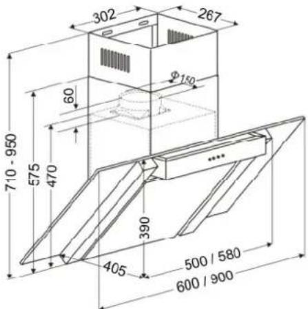 | |
| Activated carbon filter for recirculation mode (not supplied) | KF 561 (Part no. 256 100) Set: 2 units |
The right to make technical and design modifications in the course of continuous product development remains reserved.
Product data sheet for household sales head, according to regulation (EUI) Non 65/2014 65/2014
| BrandBrand | BomannBomann | |
| ModelModel | DU 667 G/ DU 668 G | |
| Annual Energy Consumption (AEC _hood ) | kWh/a | 89.6 |
| Energy Efficiency class1) | C | |
| Fluid Dynamic Efficiency (FDE _hood ) | 15.9 | |
| Fluid Dynamic Efficiency class2) | D | |
| Lighting Efficiency (LE _hood ) | lux/W | 41 / 43 |
| Lighting Efficiency class3) | A | |
| Grease Filtering Efficiency | % | 45.8 |
| Grease Filtering Efficiency class4) | F | |
| Air flow at minimum speed in normal use | m3/h | 380.2 |
| Air flow at maximum speed in normal use | m3/h | 585.7 |
| Air flow in use at intensive or boost setting | m3/h | - |
| A-weighted sound power emission in normal use | ||
| - at minimum speed | dB | 63 |
| - at maximum speed | dB | 69 |
| A-weighted sound power emission in use at intensive or boost setting | dB | - |
| Power consumption in off mode (Po) | W | - |
| Power consumption in standby mode (Ps) | W | 0.53 |
| 1) A+ (highest efficiency) to F (lowest efficiency) 3) A (highest efficiency) to G (lowest efficiency)2) A (highest efficiency) to G (lowest efficiency) 4) A (highest efficiency) to G (lowest efficiency) | ||
This appliance has been tested according to all relevant current CE guidelines, such as electromagnetic compatibility and low voltage directives, and has been constructed in accordance with the latest safety regulations.
Disposal Disposal
Meaning of the "Dustbin" SymbolMeaning of the "Dustbin" Symbol
Protect our environment; do not dispose of electrical equipment in the domestic waste.
Please return any electrical equipment that you will no longer use to the collection points provided for their disposal.
This helps avoid the potential effects of incorrect disposal on the environment and human health.
This will contribute to the recycling and other forms of reutilization of electrical and electronic equipment.
Information concerning where the equipment can be disposed of can be obtained from your local authority.

WARNING: WARNING:
Remove or disable any existing snap and bolt locks, if you take the appliance out of operation or dispose it.
BOMANN®


- WARNING
- CAUTION:CAUTION
- General Notes General Notes
- WARNING: WARNING:
- Special safety Information for this Uspecial safety Information fo
- Unpacking the Appliance Unpacking the Appliance
- i NOTENOTE
- Overview of the Appliance Overview of the Appliance
- Supplied parts Supplied parts
- Installation
- AssemblyAssembly
- CAUTIONCAUTION
- i NOTENRecommendeds for preparation work
- Installing the activated carbon filling into the activation mode
- Electrical connection Electrical connection
- Startup / Operation
- Cleaning and Maintenance
- WARNING: Risk of fire!
- CAUTION:CAUTION:
- RepairsRepairs
- TroubleshootingTroubleshooting
- Before you contact an authorized specialist
- i NOTE:NOTE:
- BOMANN®
Brand : BOMANN
Model : DU 668 G
Category : Range hood