
JDS3130B - Range hood JUNO - Free user manual and instructions
Find the device manual for free JDS3130B JUNO in PDF.


| Product Type | Built-in Cooker Hood |
| Model | JDS3130B |
| Brand | Juno |
| Installation Type | Under-cupboard or Wall-mounted with front panel |
| Exhaust Type | External (120 mm pipe) or Internal recirculation with charcoal filter |
| Motor Speed Settings | 3 speeds (0-1-2-3) with continuous adjustment |
| Lighting | Olive-shaped max 40W, E14 bulbs |
| Controls | Top switch for motor speed, bottom switch for light; front panel opens/closes to start/stop |
| Filter Type (Grease) | Washable metal grease filter |
| Optional Filter (Charcoal) | Replaceable circular charcoal filter (replace every 4 months) |
| Recommended Distance above Electric Cooktop | ≥65 cm |
| Recommended Distance above Gas Cooktop | ≥75 cm |
| Pipe Diameter | 120 mm |
| Power Supply | Standard household voltage (220-240V, 50Hz) via plug or permanent connection with 2-pole switch |
| Grease Filter Maintenance | Clean at least once a month by hand or dishwasher (60°C) with suitable detergents |
| Charcoal Filter Maintenance | Replace every 4 months; cannot be washed or regenerated |
| Exterior Cleaning | Use cloth moistened with denatured alcohol or neutral liquid detergents; avoid abrasives |
| Safety Feature | Auto shut-off when front panel is closed; must have flap mounted to switch on |
| Included Accessories | Mounting hooks, screws, wall plugs, angle frame, deflector for recirculation, installation schemes |
| Bulb Replacement | Disconnect power, remove inlet grid, replace with max 40W E14 olive-shaped bulb |
Frequently Asked Questions - JDS3130B JUNO
User questions about JDS3130B JUNO
0 question about this device. Answer the ones you know or ask your own.
Ask a new question about this device
Download the instructions for your Range hood in PDF format for free! Find your manual JDS3130B - JUNO and take your electronic device back in hand. On this page are published all the documents necessary for the use of your device. JDS3130B by JUNO.
USER MANUAL JDS3130B JUNO
Instructions on mounting and use of the cooker hood
JDS 3130
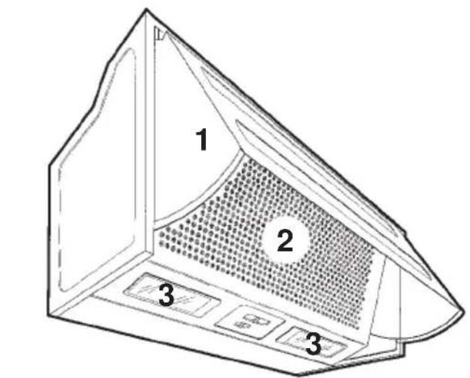
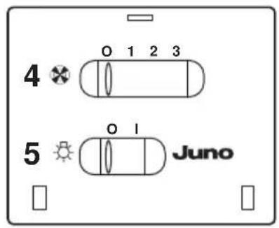
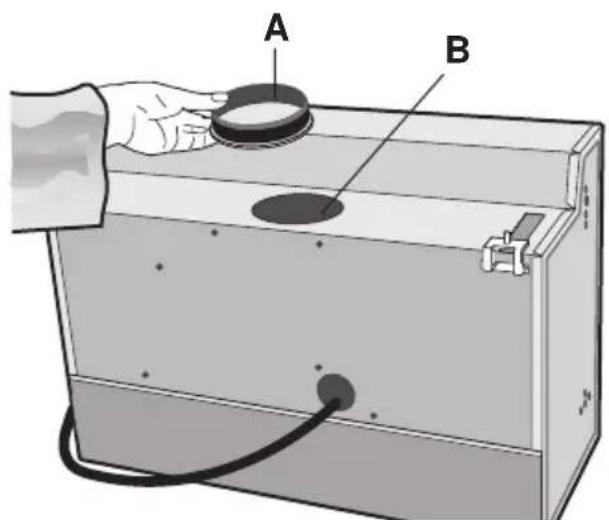
Fig. 1
natural_image
Technical line drawing of a mechanical device with cylindrical components and wiring (no text or symbols)Fig. 2
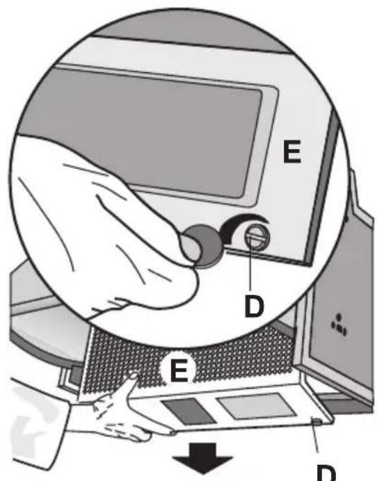
Fig. 3
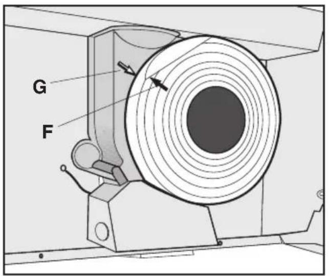
Fig. 4
natural_image
Line drawing of a battery pack with open lid and wire, no text or symbols presentFig. 5
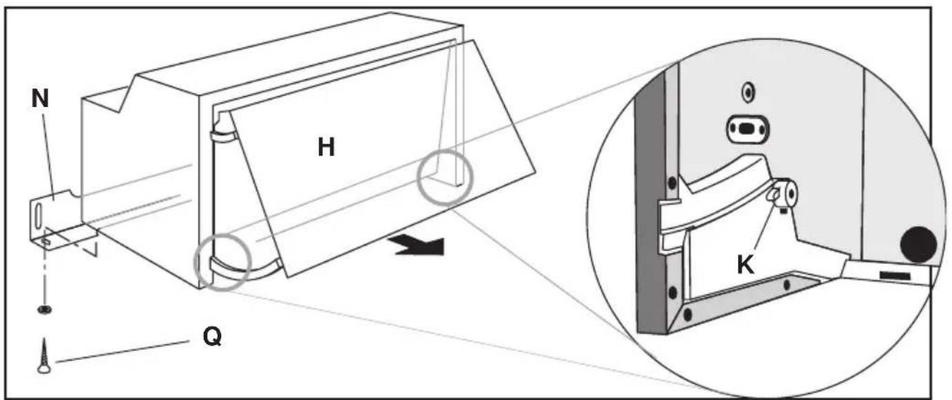
Fig. 6
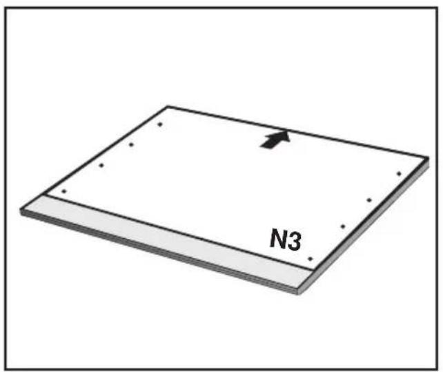
Fig. 7
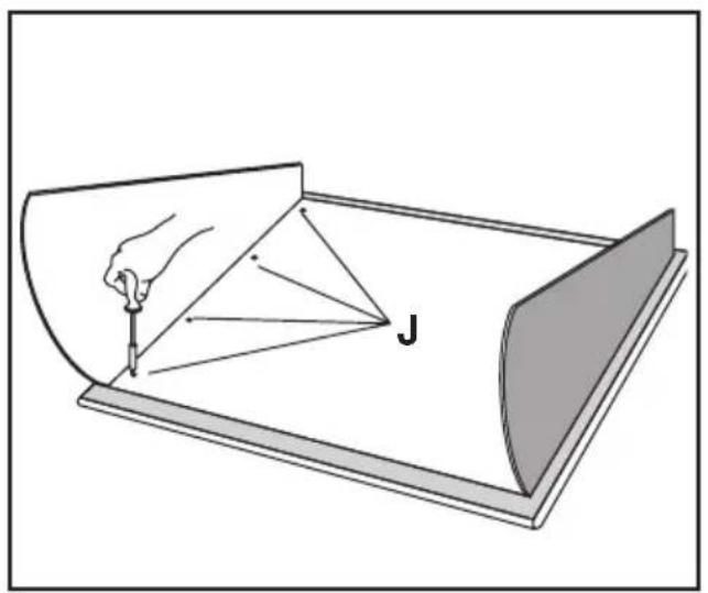
Fig. 8
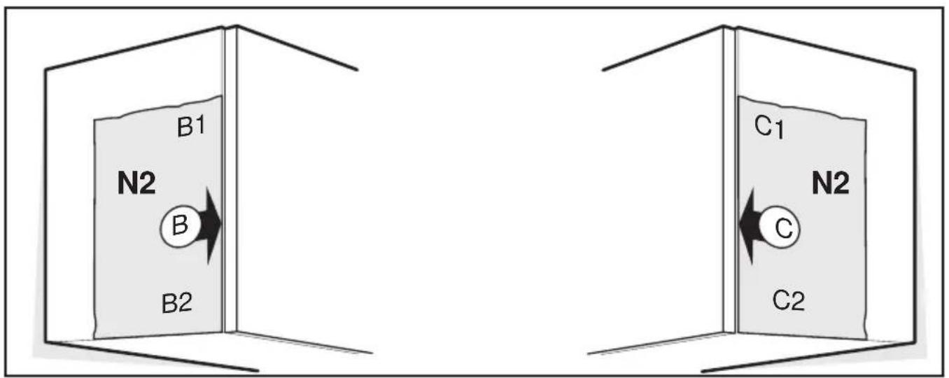
Fig. 9
Fig. 10

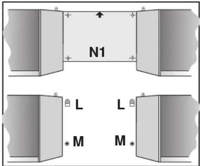
Fig. 12
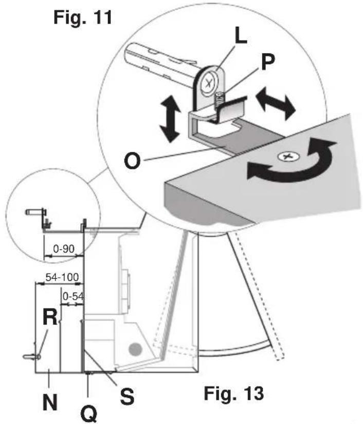
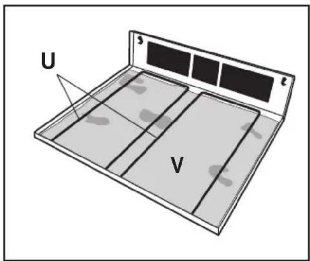
Fig. 14

Geräteansicht
1) Flap
2) Grease filter supporting grid
3) Cooking surface lighting
4) Motor speed selector
5) Light switch
Use
Two systems are available:
External exhausting system
In this case the fumes are conveyed outside by means of a special pipe connected with the coupling flange A, placed in the hole B (Fig. 1).
Choosing the exhausting pipe
The coupling flange A has a diameter of 120mm.
We suggest to use ∅ 120 mm exhausting pipe.
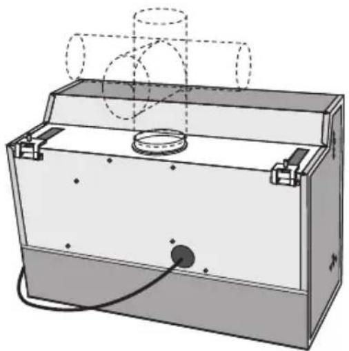
According to your installation the pipe can be directed either towards the ceiling or towards the walls (Fig. 2).
Internal recycle system
— The air is purified through an active carbon filter and returned to the room.
— The use of an active carbon filter is necessary when an exhaust pipe to the exterior is not available, or when it is not possible to install this type of pipe.
In the case of the internal recycle version proceed as follows:
a. Request an active carbon filter suitable for this model from your supplier.
b. Remove the inlet grid E turning the locks D and pull it out downwards (Fig. 3).
c. Position the activated charcoal filter over the protective grate for the exhaust fan so that the reference points G and F coincide (Fig. 4). Then turn it in the clockwise direction until the filter is locked in place.
d. Refit the inlet grid.
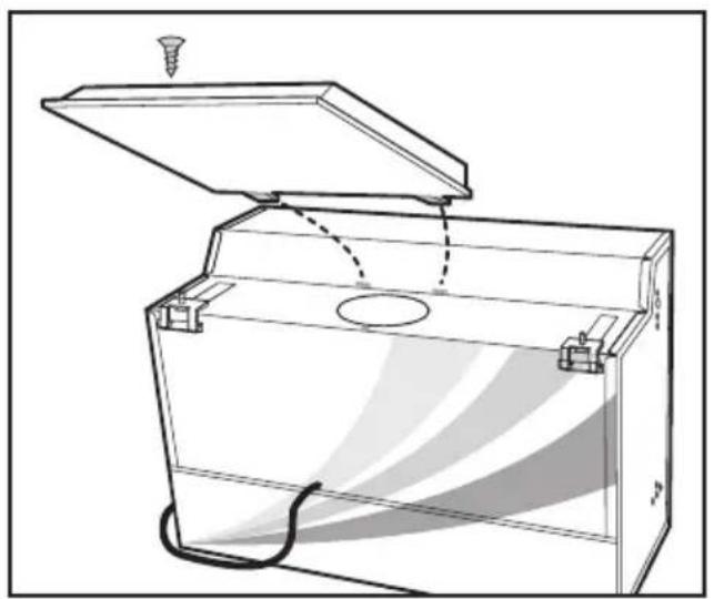
e. The deflector (Fig. 5) must be fitted on the hole B (Fig. 1) fixing it with the screw provided.
The deflector conveys the air frontwards avoiding to dirty the rear wall.
Attention
When installed, the hood must be not less than 65 cm. above electric burners or 75 cm. above gas or mixed-fuel burners.
Warning!
— The hood cannot be connected to flues of other appliances that run on energy sources other than electricity.
— When the hood is used at the same time of other appliances that run on energy sources other than electricity, provision must be made for an adequate supply of air.
— No food must be cooked flambé underneath the hood.
The use of an unprotected flame is dangerous for the filters and could cause fires.
Therefore, never use an open flame under the hood. When frying foods, never leave the pan alone because the cooking oil could flare up.
— Please, keep to the provisions of official directives regarding the question of fume discharge.
— The manufacturers refuse to accept any responsibility for damage to the hood or its catching on fire because of failure to observe the above instructions.
Suggestions for the installation and use of the hood
— The horizontal sections of the pipe must be slanted slightly upwards (about 10%) to ensure an easy flow of the air outwards.
— The best performance of the unit is obtained in the external exhaust model (suction), therefore in the limits of the possibilities it is advised to use the external exhaust (suction) type.
— The best performances are obtained with short pipes (max. 4 m) and with few curves.
Electric connection
Before completing any connection, make sure the house voltage corresponds with the voltage indicated on the label affixed inside the hood.
The hood is supplied with a standard plug; connect it to a correspondingly standard socket.
In the case is intended to connect the appliance permanently to the mains after having removed the plug supplied, must be fitted a two-pole switch conforming to regulations with an opening distance between contacts of not less than 3mm.
The manufacturers are not liable for any problems caused by the user's failure to observe the above instructions.
Fixing the hood
Mounting the hood on the wall
Make use of the scheme N1 provided, applying it on the wall.
Drill where indicated (fig. 12).
Place the hooks L provided with screws and blocks in the upper holes.
Place the expansion plugs M supplied with the hood in the lower holes (fig. 12).
Fix the angle frame N (using either the long or the short arm, depending on the depth of the side cupboards) to the wall at the right height.
Adjust the position of the upper brackets O, fix the hood to the hooks L, check that the hood is at the right height (to eventually adjust the height work on the screws P, fig. 13).
Fix the hood to the lower angle frame by means of the screws Q.
For a further adjustment act on the screws R through the holes S (fig. 13).
Fixing the front panel
Take off the door H (fig. 6) turning the rear locking knobs K.
Apply the scheme N3 on the rear side of the front panel, considering that the arrow indicates the upper side (fig. 7), drill where indicated by the scheme.
Then fix the door to the front panel by means of the screws J (fig. 8).
Fixing the hood to the cupboards
Apply the scheme N2 on the side of the right cupboard, so that the side B matches the front part of the cupboard (disregard the thickness of the flap) and drill two holes 2,5 mm diameter in the points B1 and B2 (fig. 9).
Then apply the same scheme on the side of the left cupboard, matching the side C with the front part of the cupboard (disregard the thickness of the flap).
Drill two holes 2,5 mm diameter in the points C1 and C2 (fig. 10).
Fix the hood to the cupboards by means of the screws T (fig. 11).
Replace the door, inserting it first in the upper then in the lower slides, turn the rear locking knobs and then mount the grill, following in reverse, the operations described under paragraph "Internal Recycle version".
Adjust the angle frame tightly to the wall, making use of the apposite screws Q (fig. 13).
Using the hood
The hood JDS 3130 is supplied with a three speed motor.
To get best efficiency, we suggest to use slow speeds in normal conditions and the highest in particular cases of strong smell and vapour concentration.
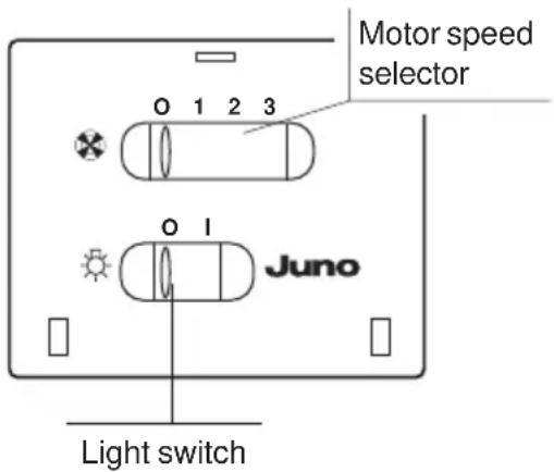
The switching plate is fitted with two switches one for continuous adjustment of the ventilator (top switch) and one for illuminating the work surface (bottom switch).
Note: Simply close the front panel to switch off the hood (light and motor).
When you pull up the front panel, the hood (light and extraction motor) switches on again as previously set.
It is advisable to switch on the extractor hood a few minutes before starting cooking and then to leave it running for approximately 15 minutes afterwards to ensure that all odours are extracted.
Attention!
The hood doesn't switch-ON if the flap is not mounted.
Maintenance
Before performing any maintenance operation, disconnect the hood from the electricity.
Grease filter
The hood has a metal grease filter.
To clean the filter, proceed as follows:
a. Open the grid by turning locks D (Fig. 3).
b. Extract the filter V after removing the clamps U (Fig. 14).
The metal grease filter lasts forever and must be washed at least once a month either by hand or in the dishwasher (60°C) with suitable detergents.
Attention! When washed in a dishwasher, the metal grease filter may discolour.
Let the filter dry without damaging it before putting it back into place.
Every time you clean the metal grease filter also clean the grid with suitable detergents without abrasive.
Charcoal filter
This hood can be equipped with a circular charcoal filter.
The charcoal filter cannot be regenerated or washed.
The charcoal filter must be replaced every 4 months.
To remove the charcoal filter, turn it in the counter clockwise direction until it comes free.
Attention
Failure to observe the rules for cleaning the appliance and changing and cleaning the filters may cause fires. Therefore, we recommend observing these instructions.
Changing the bulbs
a. Disconnect the hood from the electricity.
b. Remove the inlet grid.
c. Always replace burnout bulbs with olive-shaped max 40 Watt (E14) bulbs.
d. Refit the inlet grid.
— Before calling for Repair service because the hood fails to light up, make sure the bulbs are screwed in tightly.
Cleaning
To clean the outside of the hood use a cloth moistened with denatured alcohol or neutral liquid detergents.
Never use products containing abrasive.
Wipe brushed stainless steel in the same direction as the brushing to avoid scratching.
- Geräteansicht
- Use
- External exhausting system
- Choosing the exhausting pipe
- Internal recycle system
- Attention
- Warning!
- Suggestions for the installation and use of the hood
- Electric connection
- Fixing the hood
- Mounting the hood on the wall
- Fixing the front panel
- Fixing the hood to the cupboards
- Using the hood
- Attention!
- Maintenance
- Grease filter
- Attention! When washed in a dishwasher, the metal grease filter may discolour.
- Charcoal filter
- The charcoal filter must be replaced every 4 months.
- Changing the bulbs
- Cleaning
Brand : JUNO
Model : JDS3130B
Category : Range hood