
FS 413 - Concrete saw HUSQVARNA - Free user manual and instructions
Find the device manual for free FS 413 HUSQVARNA in PDF.
| Product type | Thermal concrete saw |
| Brand | HUSQVARNA |
| Model | FS 413 |
| Engine | Gasoline, 4-stroke, Honda GX390 (13 hp / 9.7 kW) |
| Compatible blade diameter | 250 mm to 500 mm (10" to 20") |
| Maximum cutting depth | 192 mm with 500 mm blade |
| Spindle speed | 2600 rpm |
| Rated engine speed | 3600 rpm |
| Nominal weight | 124 kg |
| Maximum weight (with accessories) | 158 kg |
| Water tank capacity | 25 liters |
| Starting type | Pull cord (manual starter) |
| Water supply | Integrated water faucet + optional tank |
| Parking brake | Yes (on EU models) |
| Emergency stop | Emergency stop switch on handlebar |
| Adjustable cutting depth | Yes, with depth stop and indicator |
| Adjustable blade guard | Can be mounted on right or left |
| Adjustable handlebar | Yes, multiple positions |
| Sound level (acoustic power) | 102.6 dB(A) |
| Sound level (acoustic pressure) | 86.1 dB(A) |
| Routine maintenance | Check engine oil, air filter, belt tension, lubricate depth control |
| Included accessories | 13 mm and 27 mm wrenches, front pointer, blade guard |
Frequently Asked Questions - FS 413 HUSQVARNA
User questions about FS 413 HUSQVARNA
0 question about this device. Answer the ones you know or ask your own.
Ask a new question about this device
Download the instructions for your Concrete saw in PDF format for free! Find your manual FS 413 - HUSQVARNA and take your electronic device back in hand. On this page are published all the documents necessary for the use of your device. FS 413 by HUSQVARNA.
USER MANUAL FS 413 HUSQVARNA
Operator's manual (Page 3 - 35)
Read these instructions carefully and make sure you understand them before using the machine.

CONTENTS and INTRODUCTION
Contents
Section
Contents & Introduction 3
Symbols and Decals. 4-8
Safety Instructions. 9-13
Parts Identification (What Is What) 14-15
Assembly. 16-20
Operation 21-25
Maintenance & Lubrication 27-28
Trouble Shooting Guide 29
Wiring diagram. 30
Technical Data. 31-32
Accessories 33
Conformity Certificates 34
Contact Information. 35
Introduction
Thank you for purchasing your new machine from Husqvarna Construction Products. We have provided important safety messages in this manual and on the machine. Please read these messages carefully. A safety message alerts you to potential hazards that could hurt you or others. Each safety message is preceded by a symbol or the safety alert symbol (A) and one of two words, WARNING, or CAUTION.
These signal words mean:
WARNING: Indicates a hazardous situation which, if not avoided COULD result in death or serious injury.
CAUTION: Indicates a hazardous situation, which, if not avoided, COULD result in minor or moderate injury. It may also be used to alert against unsafe practices.
Each message tells you what the hazard is, what can happen, and what you can do to avoid or reduce injury. Other important messages are preceded by the word NOTICE.
NOTICE means:
NOTICE: Indicates a hazardous situation which, if not avoided, could result in property damage. Your machine or other property can be damaged if you don't follow this instruction.
The safety labels should be periodically inspected and cleaned by the user to maintain good legibility at a safe viewing distance. If the label is worn, damaged, or is illegible, it should be replaced.

WARNING!

Before operating machine, read and understand this entire operation manual & engine operation manual supplied with engine.
Be familiar with machine before operation!
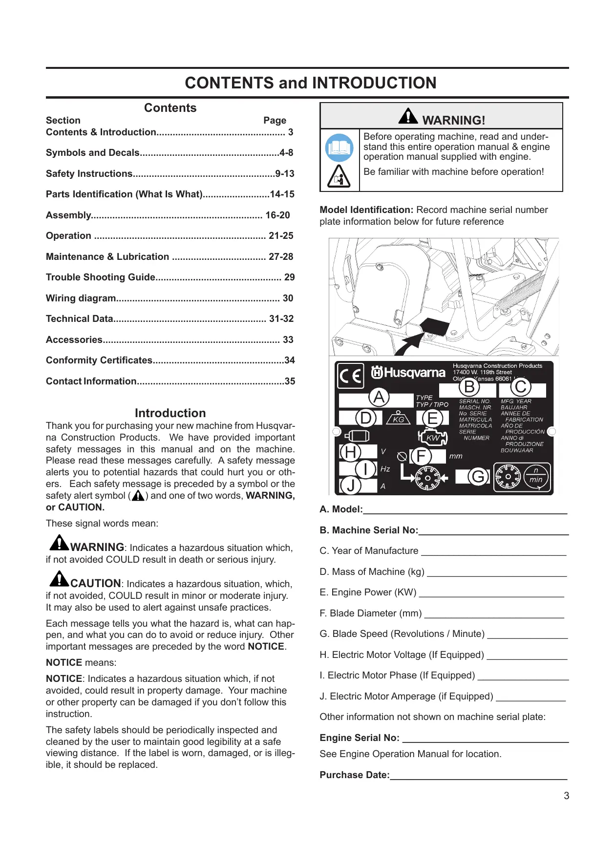
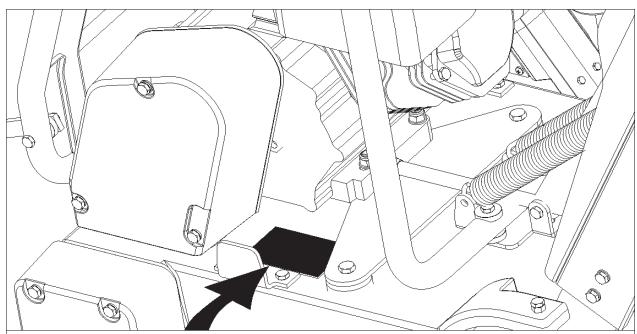
Model Identification: Record machine serial number plate information below for future reference
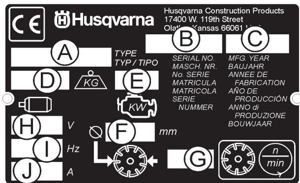
A. Model:
B. Machine Serial No:
C. Year of Manufacture
D. Mass of Machine (kg)
E. Engine Power (KW)
F.Blade Diameter (mm)
G. Blade Speed (Revolutions / Minute)
H. Electric Motor Voltage (If Equipped)
I. Electric Motor Phase (If Equipped)
J. Electric Motor Amperage (if Equipped)
Other information not shown on machine serial plate:
Engine Serial No:
See Engine Operation Manual for location.
Purchase Date:
SYMBOLS and DECALS


Please read the instructions for use prior to operating the machine for the first time.
This symbol indicates that the machine is in conformance with the applicable European directive.

Emergency Shutdown, Transmission Stop
Use In Well Ventilated Area
Do Not Use In Flammable Areas

Mandatory

Indication

Prohibition

Warning Triangle

Wear Eye Protection

Wear Breathing Protection

The use of hearing protection is mandatory

Wear Head Protection

Wear Safety Shoes

Wear Appropriate Clothing
Remove the blade prior to Hoisting, Loading, Unloading and Transporting the Machine.

Machinery Hazard, Keep hands and Feet Clear.
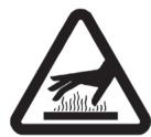
Muffler Hot. May Cause Burns and / or Ignition of Material. Avoid Contact.

Danger, Poison Exhaust Gas

No Non-working Personnel In Area
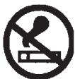
No Smoking
Do Not Operate Without Blade Guard in Place

Always Keep All Guards In Place

Water Supply On

Water Supply Off

Water Supply
SYMBOLS and DECALS

Blade Water Safety Switch

Engine Coolant Temperature

Keep Work Area Clean/Well Lit, Remove All Safety Hazards
Dangerously High Noise Level

Pay Extreme Attention to The Care And Protection Of The Machine Before Starting Up
Remove Tools From Area and Machine
Engine Oil Pressure
Oil Required

Dipstick, Maintain Proper Oil Level
Lubrication Point

High Speed

Low Speed

Electrical Switch-Off

Electrical Switch-On

Electrical Switch-Start
Repairs Are To Be Done By An Authorized Dealer Only

Headlight
Diamond Blade
Blade Diameter

Blade Engagement
Pulley diameter

Number of Revolutions Per Minute, Rotational Speed
Blade Flange Diameter

Blade Depth Stop
Cutting Depth Indicator - Depth of Cut

Parking Brake

Parking Brake Applied

Parking Brake Released
SYMBOLS and DECALS

Machine Mass (Kilograms)
Positive Battery Terminal
Blade Depth Indicator - Zero
Electric Motor
Engine

Engine Speed Revolutions/Minute

Engine Start

Unleaded Fuel Only

Husqvarna
P/N 542 19 07-33
Location: Front of Cowl
FS 413
P/N 542 19 07-112
Location: Left and Right Side of Frame
(FS 413 Only)
| For local service, please contact your local Husqvarna Construction Products representative. |
| Para efectuar un servicei local,pongase encontacto con su representante local deHusqvarna Construction Products. |
| Pour toute réparation, contacter le représentantlocal de Husqvarna Construction Products. |
| Für Service vor Ort wenden Sie sichitte anihren örtlichen Vertreter vonHusqvarna Construction Products. |
| Neem voorplaatsijke service contact op met uwplaatsijke vertegenwoordiger van deconstructieproducten van Husqvarna. |
| Per assistenza, rivolgersi al rappresentante dizone della Husqvarna Construction Products. |
| Für service pa platsen,kontakta din lokalarepresentant für Husqvarna Construction Products. |
| Para obter servicei techniquei local,contactar o representante duHusqvarna Construction Products local. |
| Europa / Europe:HusqvarnaConstruction ProductsSE-433 81 Partille,SwedenTel: +46 31 94 90 00Fax: +46 31 94 90 50 |
| Asia Pacific:HusqvarnaConstruction Products,Australia Pty Ltd25-31 Kinkaid Avenue,North plympton,Adelaide,South Australia 5037Tel:+61 (0)8 8375 1000Fax:+61 (0)8 8371 0990 |
| The Americas:Husqvarna Construction Products,North America17400 West 119th Street,Olathe, Kansas 66061 USAToll-Free Telephone:800-288-5040,Telephone:913-928-1300Fax:913-438-7938 |
P/N 542 19 06-46 Local Service Location: Side of Frame
WARNING


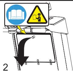
Read And Understand Entire Operation Manual Before Operating Machine! Understand AllWarnings, Instructions & Controls Before Operating Machine! Operation Manual Located Within Machine As Shown Below.
P/N 542 19 05-93
Location: Rear of Cowl
WARNING

Fill Tank Only with Water!

DO NOT Fill Tank With Gasoline Or Flammable Liquids! Injury Or Death Could Occur!
P/N 542 19 06-17
Location: Water Tank (If Equipped)
WARNING

Muffler Is HOT!
May Cause Burns And / Or Ignition Of Material.
Avoid Contact!
P/N 542 16 90-65 Location: Engine Fuel Tank, Near Muffler

P/N 542 19 06-37
Location: Top of Cowl
WARNING AVERTISSEMENT ADVERTENCIA VARNING WARNING AVERTENZA ATENCAO WAARSCHUWING
Read manual.
Veuillez tire le
IF YOU DO NOT HAVE AN OPERATING CELL FERRY 1-800-288-5046
DO NOT operate No written debt
manuel. NO dinalst denl
TATOR'S MANUAL (USA & Canada)
near combustible materials (dust, lung inflammations)
a er urilal inainable.
Machining Hazard - Maquina en funccion
- Use only in well ventilated locations. Utilizing an up-lung
Aims: Open all wounds in skin
Always keep an guard in place. Miento-Los capotes deben es
tilated areas.
muh bien ventilated.
10
。
Always wear it to utilize silicone proct.
Approved equipment.
Fecaciones homologadas.
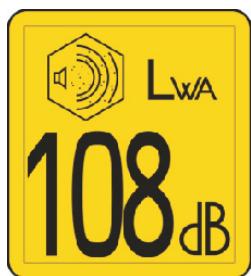
P/N 543 04 57-88 SOUND LEVEL - 108dBA
Location: Blade Guard
P/N 542 19 06-38
Location: Rear of Cowl
SAFETY INSTRUCTIONS
General use

WARNING!


Before operating machine, read and understand this entire operation manual & engine operation manual supplied with engine.
Be familiar with machine before operation!


Operator must wear personal protective equipment & clothing appropriate to the work he is doing.


Personal protective equipment, such as hearing & eye protection, is mandatory.

The working area must be completely clear, well lit and all safety hazards removed.

Any persons not involved in the work, should leave the area.

WARNING! Do not contact the tool when machine is in operation.
Fuel Safety:

WARNING! Take care when handling fuel. Bear in mind the risk of fire, explosion and inhaling fumes.
- Only store fuel in containers approved for the purpose.
- Only refuel machine with engine OFF. Never remove fuel cap and fill the fuel tank while the engine is running.
- Always refuel in a well ventilated area.
- Never fill a fuel tank indoors.
- Allow engine to cool before refueling.

Never fuel machine in vicinity of sparks or flames. Do not use machine in flammable area.
Do not smoke while fueling or using the machine.
- Move machine 10 feet (3 meters) from refueling point before starting engine.
- Never start the machine:
1) If fuel has been spilled on the machine. Wipe off spillage and allow remaining fuel to evaporate.
2) If you have spilled fuel on yourself or your clothes. Use soap and water to wash any part of your body that has come in contact with fuel.
3) If the machine is leaking fuel. Check regularly for leaks from the fuel cap and fuel lines.
- Store and transport machine and fuel so that there is no risk of any leakage or fumes coming into contact with sparks or flames, for example, electrical machinery or electric motors, electrical relays / switches, or boilers.

DUST WARNING
Cutting, especially when DRY cutting, generates dust that comes from the material being cut, which frequently contains silica. Silica is a basic component of sand, quartz, brick clay, granite and numerous other minerals and rocks. Exposure to excessive amount of such dust can cause:
Respiratory diseases (affecting your ability to breath), including chronic bronchitis, silicosis and pulmonary fibrosis from exposure to silica. These diseases may be fatal;
Skin irritation and rash; and
Cancer according to NTP and IARC
- National Toxicology Program, International Agency for Research on Cancer
Take precautionary steps
- Avoid inhalation of and skin contact with dust, mist and fumes;
- Wet cut when feasible, to minimize dust;
- Wear and ensure that all bystanders wear appropriate respiratory protection such as dust masks designed to filter out microscopic particles. (See OSHA 29 CFR Part 1910.1200)
California Prop 65 Warning:
Use of this product can cause exposure to materials known to the State of California to cause cancer and/or birth defects or other reproductive harm.

WARNING POISON EXHAUST GAS
THIS SAW IS SHIPPED FROM THE FACTORY WITHOUT A CATALYTIC CONVERTER.
THE ENGINE PRODUCES CARBON MONOXIDE EXHAUST EMISSIONS AND IS NOT SAFE FOR USE IN ENCLOSED AREAS. USE OF A CATALYTIC CONVERTER REDUCES THE CARBON MONOXIDE EXHAUST EMISSIONS, BUT STILL IS NOT SAFE FOR USE IN ENCLOSED AREAS.
USE ONLY IN WELL-VENTILATED AREAS. WORKSITE AIR QUALITY MUST COMPLY WITH OSHA 29 CFR 1910.1000 PER TABLE Z-1, LIMITS FOR AIR CONTAMINANTS.
MONITOR WORKSPACE AIR QUALITY TO INSURE COMPLIANCE. FAILURE TO COMPLY WILL RESULT IN DANGER TO LIFE AND CAUSE PERMANENT INJURY OR DEATH.
General Information
Carbon monoxide (CO) has the distinction of being one of the few commonly encountered industrial gasses that is both highly toxic (poison) and odorless. When inhaled, CO acts as a chemical asphyxiant by preferentially combining with hemoglobin in the blood stream. As a result, the hemoglobin is not able to transport its normal amount of oxygen, which results in under-oxygenation of tissues. Symptoms of low-level CO exposure include headaches, dizziness, confusion, and nausea. However, loss of consciousness, permanent injury and death may result from continued or more intense exposure. Because of the health hazards associated with CO inhalation, the Occupational Safety and Health Administration (OSHA) have imposed personal exposure limits. The OSHA exposure limits, which are specified in the 29 CFR 1910.1000 (1998 Revision), allow for a 200 PPM Ceiling Limit and a TWA of 35 PPM per 8-hour shift/40-hr workweek. It is strongly recommended that the OSHA 29 CFR 1910.1000 (Code of Federal Regulations) be consulted for more information on exposure limits for various hazardous materials. If CO Poisoning is suspected immediately remove the victim to fresh air and obtain emergency medical attention.
Proper Ventilation:
THIS SAW IS SHIPPED FROM THE FACTORY WITHOUT A CATALYTIC CONVERTER. It is important to be aware that saws with catalytic converters reduce CO and hydrocarbon (HC) emissions. The exhaust still contains CO. If the workspace is too confined or under-ventilated, CO may accumulate until it eventually exceeds OSHA limits. When this happens, action must be taken to remove workers from areas of high concentration. Operators and work area supervisors should take precautions to insure adequate ventilation of the workspace at all times. Carbon monoxide detection monitors should be used to determine that adequate ventilation exists.

WARNING HEARING HAZARD
DURING NORMAL USE OF THIS MACHINE, OPERATOR MAY BE EXPOSED TO A NOISE LEVEL EQUAL TO 85 dB (A) OR GREATER. TEMPORARY AND/OR PERMANENT DAMAGE TO HEARING MAY RESULT. HEARING PROTECTION REQUIRED.
SAFETY INSTRUCTIONS
SAFETY FIRST!
WARNING
DO'S AND DO NOT'S

WARNING: FAILURE TO COMPLY WITH THESE WARNINGS AND OPERATING INSTRUCTIONS COULD RESULT IN DEATH OR SERIOUS BODILY INJURY.
DO
DO Read this entire operator's manual before operating this machine. Read and understand all warnings, instructions, controls, and symbol definitions contained in this manual, and on the machine.
DO always give a copy of this manual to the equipment user. If you need extra copies, call TOLL FREE 1-800-288-5040 in USA, or +1-913-928-1300 for International, or see "contact information" section of this manual.
DO keep all guards in place and in good condition.
DO wear safety approved hearing, eye, head and respiratory protection.
DO read and understand all warnings and instructions on the machine.
DO keep all parts of your body away from the blade and all other moving parts.
DO know how to stop the machine quickly in case of emergency.
DO shut off the engine and allow it to cool before refueling or doing maintenance.
DO inspect the blade, flanges and shafts for damage before installing the blade.
DO use the blade flange size shown for each blade size.
DO use only steel center diamond blades manufactured for use on concrete saws.
DO use only the blade flanges supplied with the saw. Never use damaged or worn blade flanges.
DO use only blades marked with a maximum operating speed greater than the blade shaft speed. Verify speed by checking blade shaft rpm and pulley diameters and blade flange diameters.
DO verify saw drive configuration by checking blade shaft RPM, pulley diameters, and blade flange diameter.
DO read all safety materials and instructions that accompany any blade used with this machine.
DO inspect each blade carefully before using it. If there are any signs of damage or unusual wear, DO NOT USE THE BLADE.
DO mount the blade solidly and firmly, Wrench tighten the arbor nut.
DO make sure the blade and flanges are clean and free of dirt and debris before mounting the blade on the saw.
DO use the correct blade for the type of work being done. Check with blade manufacturer if you do not know if blade is correct.
DO use caution and follow the instructions when loading and unloading the machine.
DO operate this machine only in well ventilated areas. Breathing Poison Exhaust Gas could result in death.
DO instruct bystanders on where to stand while the machine is in operation.
DO establish a training program for all operators of this machine.
DO clear the work area of unnecessary people. Never allow anyone to stand in front of or behind the blade while the engine is running.
DO make sure the blade is not contacting anything before starting the engine.
DO use caution when lifting and transporting this machine.
DO always tie down the machine when transporting.
DO use caution and follow instructions when setting up or transporting the machine.
DO have all service performed by competent service personnel
DO verify the blade arbor hole matches the machine spindle before mounting the blade.
DO always check for buried hazards, such as electrical or gas lines before sawing. Always contact local utilities before operation in unknown areas.
DO move the machine at least 10 feet (3 meters) from the fueling point before starting the engine and make sure the fuel cap is on the machine and properly tightened.
DO lift machine only from specified lifting point.
DO clean the machine after each day's use.
DO use the proper blade flange size for each blade size. Never use damaged or worn blade flanges.
DO use caution when handling fuel.
DO only cut in a straight line, and only saw as deep as the job specifications require.
SAFETY FIRST!

WARNING DO'S AND DO NOT'S

WARNING: FAILURE TO COMPLY WITH THESE WARNINGS AND OPERATING INSTRUCTIONS COULD RESULT IN DEATH OR SERIOUS BODILY INJURY.
DO NOT
DO NOT operate this machine unless you have read and understood this operator's manual.
DO NOT operate this machine without the blade guard, or other protective guards in place.
DO NOT stand behind or in front of the blade path while the engine is running.
DO NOT leave this machine unattended while the engine is running.
DO NOT work on this machine while the engine is running.
DO NOT operate this machine when you are tired, fatigued or under the influence of drugs or alcohol.
DO NOT use a wet blade without adequate water supply to the blade.
DO NOT exceed maximum blade speed shown for each blade size. Excessive speed could result in blade breakage.
DO NOT operate the machine if you are uncertain of how to run the machine.
DO NOT use damaged equipment or blades.
DO NOT touch or try to stop a moving blade with your hand.
DO NOT cock, jam, wedge or twist the blade in a cut.
DO NOT transport a cutting machine with the blade mounted on the machine.
DO NOT use a blade that has been dropped or damaged.
DO NOT use carbide tipped blades.
DO NOT touch a dry cutting diamond blade immediately after use. These blades require several minutes to cool after each cut.
DO NOT use damaged or worn blade flanges.
DO NOT allow other persons to be near the machine when starting, refueling, or when the machine is in operation.
DO NOT operate this machine in an enclosed area. Breathing Poison Exhaust Gas could result in death.
DO NOT operate this machine in the vicinity of anything that is flammable. Sparks could cause a fire or an explosion.
DO NOT allow blade exposure from the guard to be more than 180 degrees.
DO NOT operate this machine with the belt guards or blade guard removed.
DO NOT operate this machine unless you are specifically trained for its operation.
DO NOT use a blade that has been over heated (Core has a bluish color).
DO NOT jam material into the blade.
DO NOT grind on the side of the blade.
DO NOT tow this machine behind a vehicle.
DO NOT operate this machine with the any guards or shields removed.
DO NOT cut deeper than 1" per pass with a dry blade. Step cut to achieve deeper cuts.
DO NOT operate this machine while under the influence of drugs or alcohol.
***************
This saw was designed for certain applications only. DO NOT modify this saw or use for any application other than for which it was designed. If you have any questions relative to its application, DO NOT use the saw until you have written Husqvarna Construction Products and we have advised you.
Husqvarna Construction Products North America
17400 West 119th Street, Olathe, Kansas 66061 USA
NOTES
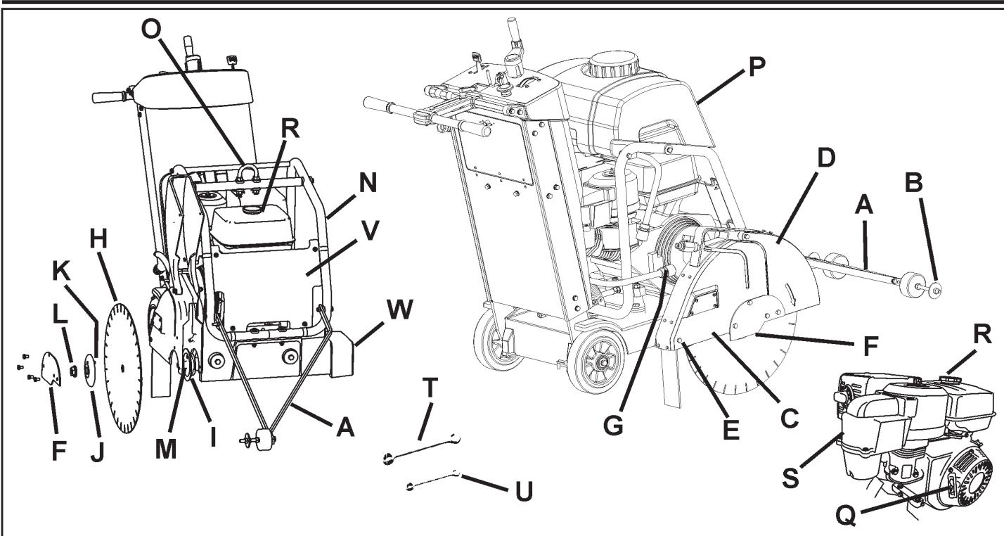
PARTS IDENTIFICATION (WHAT IS WHAT)
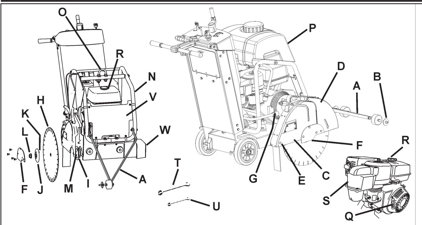
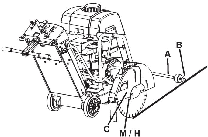
A. Front Pointer: Use to Guide machine in a straight line.
B. Guide Wheel: On Front Pointer (A). Align to cutting line and Blade (H) to produce straight cuts.
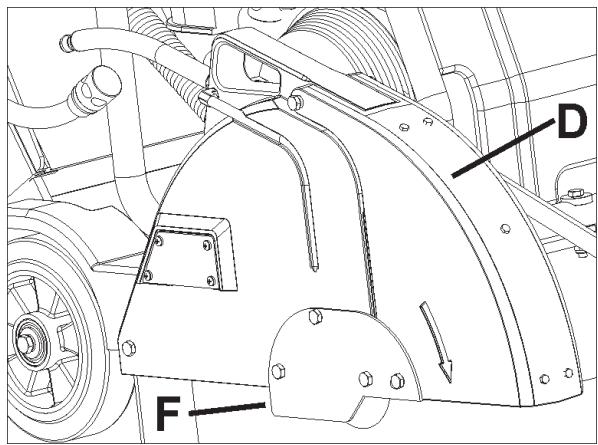
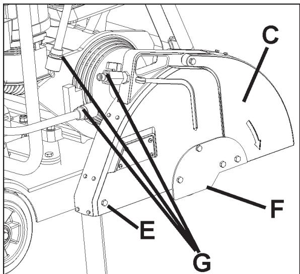
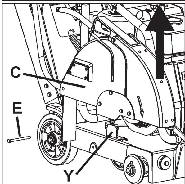
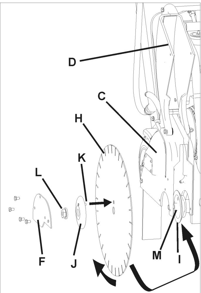
C. Blade Guard: Covers Blade (H). Must always be in place when operating machine! Note tool direction as marked on guard with an arrow.
D. Blade Guard Front: Part of Blade Guard. Can be raised to install Blade (H).
E. Blade Guard Rear Bolt: Holds Blade Guard (C) in position. Must be removed and relocated if Blade Guard (C) is moved.
F. Blade Guard Latch Plate: Covers Outer Flange (J).
G. Water Hose Disconnect (G): Connects Blade Guard (C) to Water Control Valve (KK) or Water Tank (P). Can be used when Blade Guard (C) is mounted to left or right side of machine
H. Blade: Tool that cuts asphalt or concrete material – not included with machine.
I. Inner Flange: Arbor on which the Blade (H) is mounted. Replace if Damaged or worn.
J. Outer Flange: Used to hold Blade (H) in position. Contains Locking Pin (K) that must go through Blade (H). Replace if damaged or worn.
K. Locking Pin: Holds Blade (H) in position. Replace if Damaged or worn.
L. Blade Shaft Nut (L1 / L2): Holds Outer Flange (J) to machine. Nut (L1) on right side of machine has Left Hand threads. Nut (L2)(not shown) on left side of machine has Right Hand threads.
M. Blade Arbor: Blade (H) mounts on this surface.
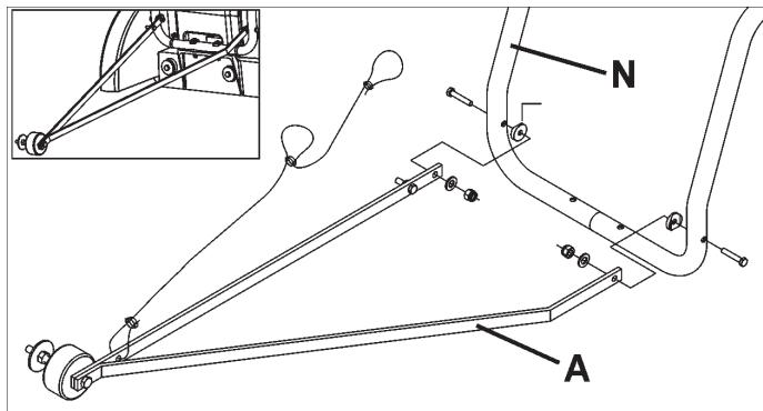
N. Water Tank / Lifting Point Support: Holds Water Tank (P). Supports Lifting Point (O).
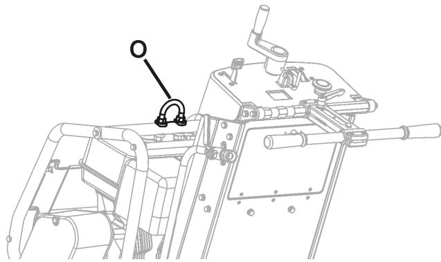
O. Lifting Point: Lift machine only from this point!
P. Water Tank (If Equipped): 25 Liter (6.6 U.S. Gallon) water capacity. Fill only with water! Do not fill with gasoline or other flammable substances! Use only for dust suppression when cutting dry. Use only with laser welded (dry) Diamond Blades (H).
Q. Engine Starting Rope: Use to start engine. See engine operation manual.
R. Engine Fuel Tank: Fuel fill point. See engine operation manual.
S. Engine Air Cleaner: Check daily. Clean every four (4) hours if cutting in dusty conditions. See engine operation manual.
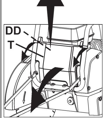
T. Blade Shaft Wrench (27mm): Use for installing and removing Blade (H). Store in Tool Compartment (BB).
U. Wrench (13mm): Use for many maintenance items on machine. Store in Tool Compartment (BB).
V. Front Cover: Clips to Water Tank Support (N). Open to turn Engine Start Switch (DD) ON (1) or OFF (0).
W. Shaft Guard: Protects Inner Flange (I). Always installed on opposite side of frame to Blade Guard (C).
X. Depth Control Grease Fitting: Not Shown. See Maintenance section of this document.
Y. Blade Guard Mounting Spade: Holds Blade Guard (C) in position.
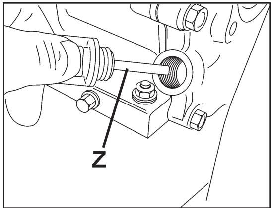
Z. Engine Oil Dipstick: Use to check engine oil level (Not Shown - See Operation Section of this document).
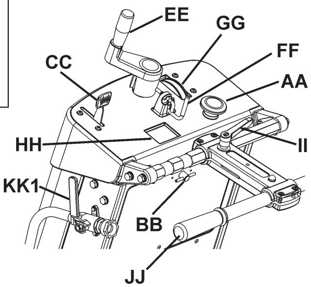
AA. Emergency Stop Switch: Depress Switch to STOP engine in emergencies. Reset by pulling outward (pull up) to allow re-starting of machine.
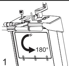
BB. Tool Compartment: Contains Operation Manual, Parts List, & two wrenches (T & U) (13mm & 27mm). Open by turning knob 180 degrees. Always return Operation Manual to this area for future reference.
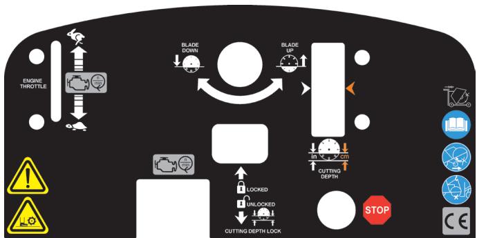
CC. Engine Throttle: Controls Engine speed (RPM). Push forward to increase engine speed. Pull backwards to decrease engine speed. All sawing is done at maximum engine speed.
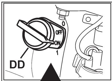
DD. Engine Start Switch: Located on engine, behind Front Cover (V). Must be ON (1) to start engine. Use to turn engine OFF ("0") in non-emergency situations.
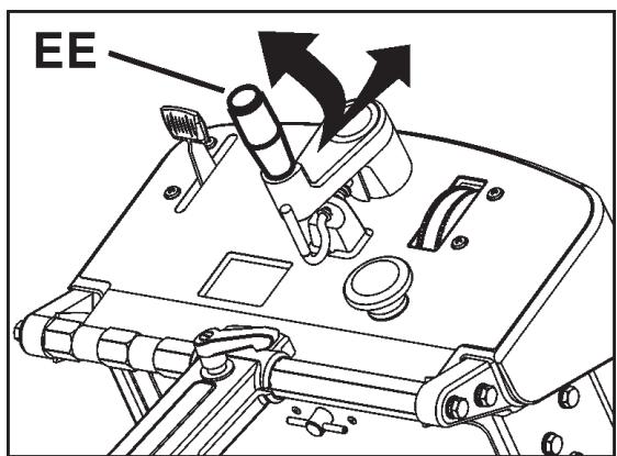
EE. Blade Depth Control: Turn Counter-Clockwise to raise Diamond Blade (H) and Clockwise to lower Diamond Blade (H).
FF. Blade Depth Stop: To Lock Blade Depth Control (EE) in position. Pull Blade Depth Stop toward rear of machine and turn 90 degrees to lock in open position.
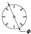
GG. Blade Depth Indicator: Shows cutting depth of Diamond Blade (H) in centimeters (orange color) and inches (white color). Operation: With engine OFF ("0"), lower Diamond Blade (H) until in contacts the cutting surface. Rotate Blade Depth Indicator to align "0" with arrows. Raise Saw. When saw is lowered into cut, current cutting depth is shown.
HH. Engine Tachometer (RPM): Shows engine speed in revolutions per minute if engine is running. Shows total operation time when engine is OFF ("0"). Total operation time shown in minutes from 0-59 minutes, and hours for 60+ minutes.
II. ---
JJ. Rear Handle: Operator position is behind machine with both hands on Rear Handle. Handle is adjustable to several positions.
KK1. Water Control Valve: Controls water flow to blade. Located on Left side of machine, near Rear Handle (RR). Not used with the water tank (if equipped).
KK2. Blade Guard Water Control Valve: Controls the water flow to the blade. Located on blade guard. Used with water tank (if equipped).
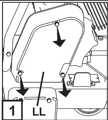
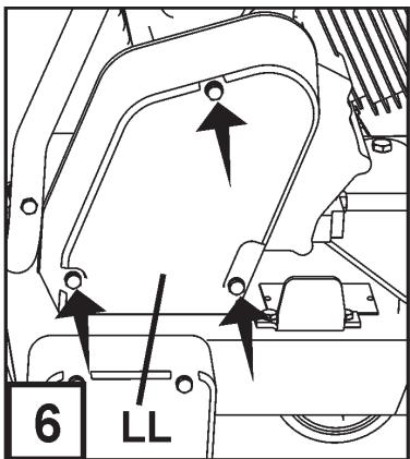
LL. Belt Guard (Not Shown): Covers engine drive belt.
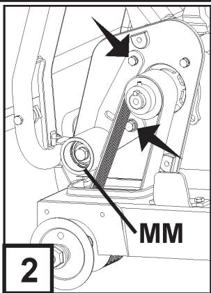
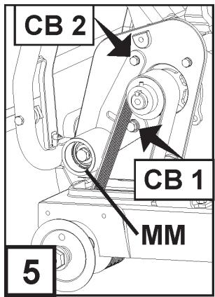
MM. Belt Drive Idler: Used to hold tension on Blade Shaft Drive Belt.
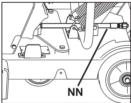
NN. Oil Drain Hose: Use to remove oil from engine.
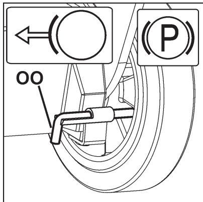
OO. Parking Brake (EU units only): Use to hold machine in parked position. Located at Right Rear Wheel, at rear of machine. Operation: To engage, rotate lever upward, so rod is allowed to move inward. To dis-engage, pull rod inward and rotate downward so rod is fixed in the inward position.
Assemble the following items before operating machine for the first time.
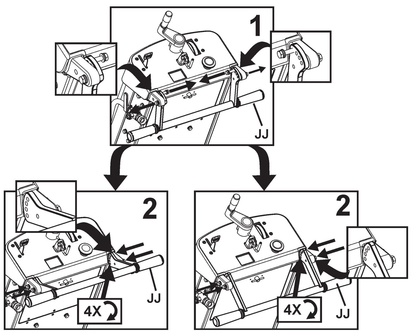
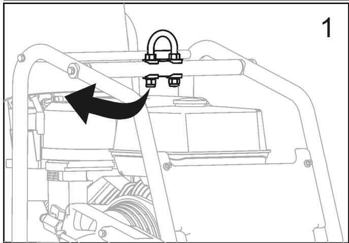
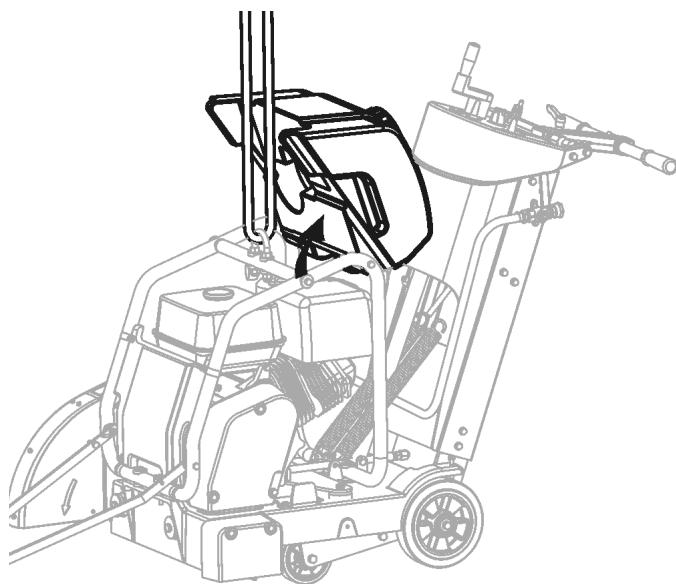
Re-Position Rear Handle (JJ): Rear Handle (JJ) is shipped in storage position shown. It must be repositioned to use the machine.
Install Front Pointer (A):
- Using screws, washers and nuts installed in the Front Pointer (A), install onto tube frame of Water Tank Support (N). Adjust locking nuts to allow Pointer (A) to pivot freely.
- Route pointer rope to avoid hot surfaces. Two loops in rope allow attachment to Rear Handle (JJ).
Note: "Single Pointer" (A) shown. Some regions have "Dual Pointer" as standard equipment. For all regions, Dual Pointer is available as an accessory. See "accessories" section of this document, or spare parts list for more information.
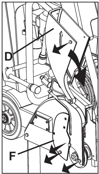
Blade Guard Front (D):
-
Using 13mm Wrench (U) provided, remove two (2) M8 screws located in front of and below Blade Guard Latch Plate (F), and the M8 screw in Blade Guard Front (D) [as indicated by arrows]. Lossen, but do not remove, remaining screw Blade Guard Latch Plate (F). Rotate Blade Guard Latch Plate (F), and Blade Guard Front (D) downward.
-
Reinstall three (3) M8 screws in Blade Guard Latch Plate (F) as shown in the diagram at the right. Use the 13mm Wrench (U) (supplied) to securely tighten the four (4) M8 bolts that hold the Blade Guard Latch Plate (F) in position.
Re-Position Blade Depth Control Handle (EE):
Pull outward on Blade Depth Control Handle (EE) and rotate 90 degrees until is snaps in position shown.

WARNING!
Blade Guard Latch Plate (F) Must Be Installed before operation. Failure to Install before operating machine could create a Hazardous situation!
Always keep all guards in place when operating machine!
ASSEMBLY
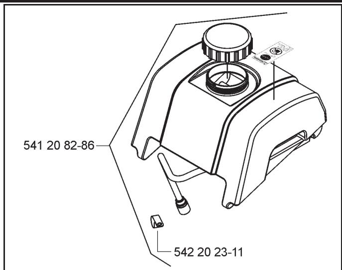
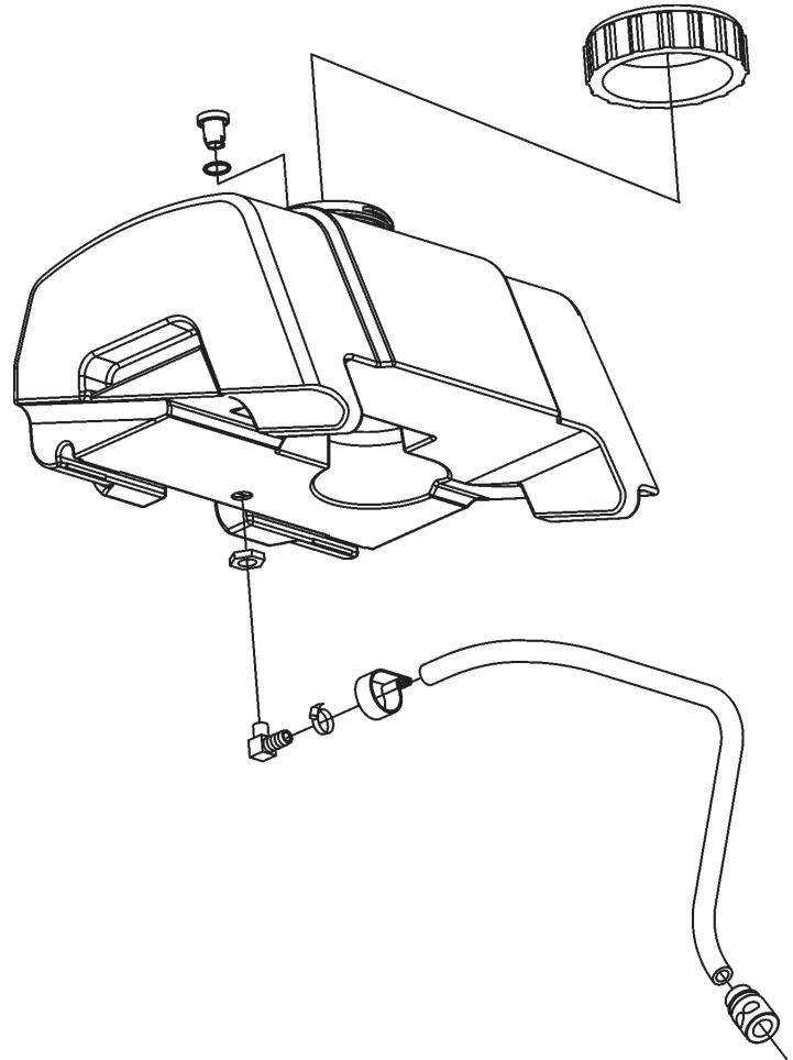
Install Water Tank (P) (if equipped):
- A factory installed water tank is available in some regions. An optional water tank kit is available for all regions.
- If water tank was previously installed on machine, read these instructions to verify that installation is correct. Follow all WARNINGs for installation and use of the Water Tank.
-
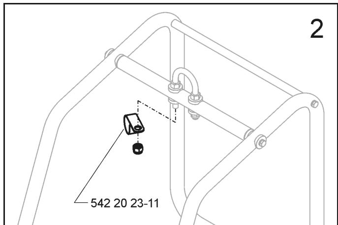
Verify the contents of the Water Tank Kit See Diagram at right.
-
Temporarily remove the right hand (same side of machine as engine starter rope) NUT from Lifting Eye (O). See diagram at right.
- Install CLAMP supplied in Water Tank Kit (P), and then reinstall the NUT. See diagram at right.
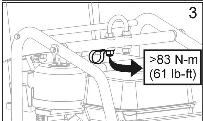
- Torque as specified below, and diagram at right.
| NOTICE |
| Torque Lifting Eye NUT to 83 N-m (61 lb-ft) mini- mum. |
| WARNING! |
| Torque NUT as specified, else failure of LIFTING EYE (O) could occur. Injury or death could occur if LIFT-ING EYE fails while lifting machine. |
ASSEMBLY
- Position Water Tank, and route Water Tank Hose as shown in Diagram at right.
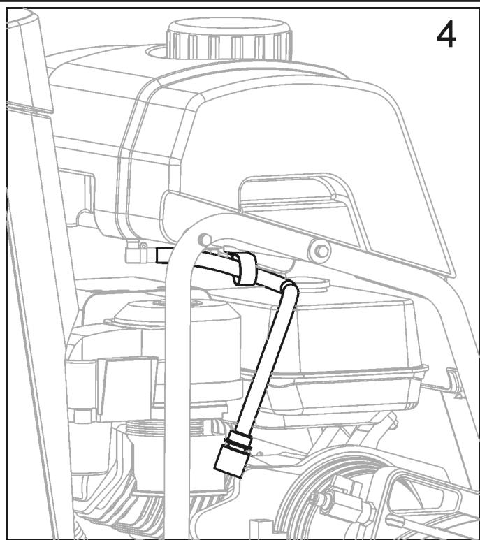
-
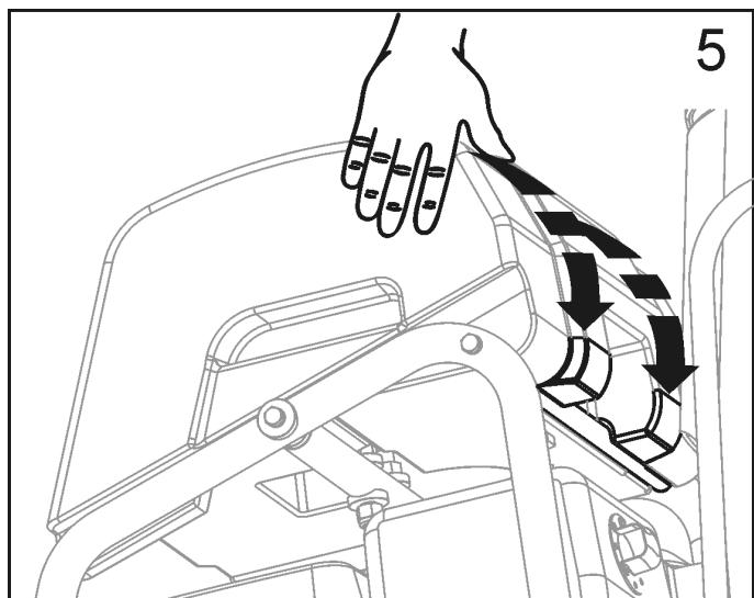
Align rear bar and recessed area at rear of water tank.
-
Press down firmly on water tank so it snaps in position onto rear bar.
- When properly installed, water tank should pivot freely on rear bar.
- Disconnect existing water hose from blade guard. This is the water hose from water control valve mounted on saw.
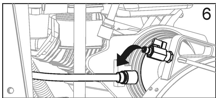
-
Connect Water tank hose to blade guard water valve.
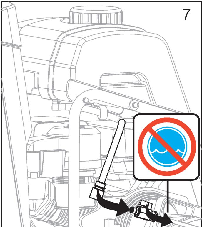
-
Verify that blade guard water valve is in the OFF position.
- The water tank hose is now assembled to the saw.
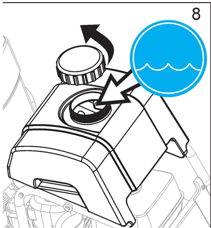
Filling Water Tank:
-
Remove the cap by turning counter clockwise. See diagram at right.
-
Fill water tank only with water. Read all WARNINGS before using water tank.
- Re-install the cap by turning clockwise.
- Water tank is designed only to suppress airborne concrete dust, and should only be used with "dry" cutting diamond blades.

WARNING!
DO NOT use conventional (wet) diamond blades with water tank as water source. Water flow is not sufficient to properly cool blade!
Fill Water Tank Only With Water!
Never fill Water Tank (P) with flammable liquids or gasoline, else injury or death could occur!
Before Operation:
Use: This machine is used only for wet or dry sawing of old and new concrete and asphalt.

WARNING!
DO NOT use for dry cutting in European Union (EU) regions. Machine is not equipped with a dust port.
Tools: Use machine only with the following tools (H): Water Cooled Diamond Blades. Reinforced Abrasive Blades or Dry Cutting Diamond blades should NOT be used within European Union (EU) regions because this machine, as supplied, does not include a dust collector port.
Diameter: 300mm (12") - 500 mm (20").
Bore: 25.4mm (1.00").

WARNING!
DO NOT use carbide, wood saw, or circular saw blades on this machine, else injury or death could occur.
Re-Locating the Blade Guard (C) - If Required:
Blade Guard (C) is factory installed on right hand side of machine, but can be relocated to left side. This may allow cutting closer to obstacles, if approaching them from the opposite direction is not possible.
- Use 13mm Wrench (U) to remove Blade Guard Rear Bolt (E) from Blade Guard (C).
- Push back collar to separate Water Hose Disconnect (G). Male half remains with Blade Guard (C). Female half remains with Water Tank (P) or Water Control Valve (KK).
- Lift Blade Guard (C) upward, and off of Blade Guard Mounting Spade (Y).
- Use 13mm Wrench (U) to remove four (4) screws that attach Blade Guard Latch Plate (F). Re-attach the Blade Guard Latch Plate (F) to the left hand side of Blade Guard (C).
- Remove and relocate Shaft Guard (W) from left hand side of machine to right hand side.
- Lower Blade Guard (C) onto Blade Guard Mounting Spade (Y) on left hand side of machine.
- Re-Install Rear Bolt (E) in Blade Guard (C).
- Re-Attach Water Hose Disconnect (G) from Blade Guard (C) to Water Tank (P) or Water Valve (KK). Take care that relocated hose will not contact muffler.
- Relocate and realign Front Pointer (A) so Guide Wheel (B) is on left side of machine.

WARNING!


Before operating machine, read and understand this entire operation manual & engine operation manual supplied with engine.
Be familiar with machine before operation!


Operator must wear personal protective equipment & clothing appropriate to the work he is doing.
Personal protective equipment, such as hearing & eye protection, is mandatory.
OPERATION
Transporting & Lifting Machine:
- Lift machine only from Lifting Point (O).
- Always remove Blade (H) before lifting, loading, or transporting.
- Use a proper lifting strap rated for at least the maximum mass of the machine. The nominal and maximum mass of the machine are shown in the TECHNICAL DATA section of this document.

Remove Blade (H) before lifting, loading, or transporting machine.
Lifting machine equipped with Water Tank:
-
Before lifting a machine equipped with a water tank:
-
Empty water from tank.
- Remove Blade.
- Lower machine until frame is parallel to ground.
- Pivot front of water tank upward until it rests against aluminum cowl top. Do not rest water tank cap against plastic cowl front - damage during lifting could occur.
- Attach proper lifting strap to Lifting Point (O).
- Test Lift machine at a low level (just a few centimeters) to verify tank remains secured to machine, and will not be damaged or cause damage.
- If water tank equipped machine can not be lifted without damage to the machine or tank, remove water tank before lifting.
NOTICE
Water tank or saw could be damaged if saw is not lifted properly. Closely monitor for damage while lifting machine.
Parking Machine:
- Machines used in some regions are equipped with a Parking Brake.
- Parking brake is designed to hold machine in position on a slope of 10 degrees or less, with rear of machine on downhill side of slope (maximum weight on braked wheel).

Parking Brake - Engage (See Diagram): Move parking brake lever (OO) from the dis-engaged position:
- Pull lever (OO) toward center of machine.
- Rotate lever (OO) upward 180 degrees.
- A spring allows lever (OO) to move toward outside of machine, to engage against wheel hub.
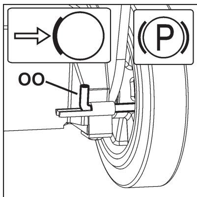

Parking Brake - Dis-engage (See Diagram): Parking brake must be dis-engaged to operate machine.
- Pull lever (OO) toward center of machine.
- Rotate lever (OO) downward 180 degrees and release to lock in position.
Gasoline Engine Models:
Refer to the engine operating manual for proper engine operation.
FUEL: Unleaded gasoline is recommended. See engine operation manual for more information.
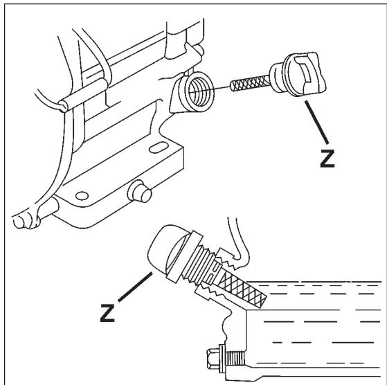
OIL: Check that engine oil level is correct using the Engine Oil Dipstick (Z). When checking the engine oil level, the Engine Oil Dipstick (Z) should not be screw into the port. Because the engine often operates at an angle, check oil level with engine horizontal. Check frequently to ensure that oil level never falls below lower mark on dipstick. 10W30 oil is recommended. See engine operation manual for more information.
NOTICE
If engine is equipped with a low oil shutdown system, engine will not start if oil level is low. Also, engine may stop if maximum angle of operation is exceeded. See engine operation manual.
All Models:
Front Pointer (A) must be checked for alignment with blade. Lay a straight edge along Inner Flange (I). Align Front Pointer (A) to straight edge. If required, adjust Front Pointer (A) by loosening nuts that hold Guide Wheel (B) in place. Align Guide Wheel (B) to straight edge and retighten nuts.
Check that water tubing in the Blade Guard (C) is open and that each side of blade has an adequate supply of water.
Test the water supply for pressure and quantity (flow) before starting the saw.
Saw only as deep as the job specifications require. Sawing deeper than required will add excessive wear the blade and machine.
Cut in increments of 50mm (2 inches) deep until cutting depth specification is reached. This is known as "step cutting".
Saw only in a straight line. Mark cutting line clearly so saw operator can follow line without difficulty. Saw should NOT be twisted from side to side to force blade back on line.
OPERATION
Fitting the Diamond Blade (H):

Install Diamond Blade (H) at job site. Do not transport the machine with the Diamond Blade (H) installed.
- Open Front Cover (V).
- Set Engine Start Switch (DD) to OFF ("0") position.
- Raise Diamond Blade (H) to highest position by turning Blade Depth Control (EE) Counter-Clockwise.
- Use 13mm Wrench (U) located in Tool Compartment (BB), to loosen and remove four (4) M8 bolts that attach Blade Guard Latch Plate (F). Temporarily remove Blade Guard Latch Plate (F).
- Raise Blade Guard Front (D).
- Using the 27mm Blade Shaft Wrench (T), loosen and remove the Blade Shaft Nut (L) that secures the Outer Flange (J) in position.
NOTICE
Blade Shaft Nut (L1) on right hand side of machine has left hand threads. To loosen, turn clockwise.
Blade Shaft Nut (L2)(not shown) on left hand side of machine has right hand threads. To loosen, turn counter-clockwise.
- Remove Outer Flange (J).
- Check that Blade Shaft Arbor (M), Inner Flange (I), and Outer Flange (J) are clean and free of foreign objects.
- Fit Diamond Blade (H) onto Blade Shaft Arbor (M). Direction of rotation is shown by arrows on Diamond Blade (H) and Blade Guard Front (D). See diagram at right.
- Install Outer Flange (J) onto Blade Shaft Arbor (M). Make sure that Locking Pin (K) passes through Diamond Blade (H) and into Inner Flange (I).
- Rotate Outer Flange (J) and Diamond Blade (H) in opposite direction of blade rotation to remove backlash.
- Install Blade Shaft Nut (L). Tighten using 27mm Blade Shaft Wrench (T).
NOTICE
Blade Shaft Nut (L1) on right hand side of machine has left hand threads. To tighten, turn counter-clockwise. Torque to 45 N·m (33 lb-ft) - minimum.
Blade Shaft Nut (L2)(not shown) on left hand side of machine has right hand threads. To tighten, turn clockwise. Torque to 45 N·m (33 lb-ft) - minimum.
- Lower Blade Guard Front (D).
- Re-install and tighten Blade Guard Latch Plate (F).

WARNING!
USE ONLY Blades (H) marked with a maximum operating speed greater than blade shaft speed of machine.
DO NOT operate machine without proper guard over Diamond Blade (H)!
DO NOT operate machine with Front Blade Guard (D) raised!
Blade (H) exposure MUST NOT exceed 180 degrees when operating machine!
Contact Surfaces of Blade Shaft Arbor (M), Inner Flange (I), and Outer Flange (J) MUST BE clean and free of foreign objects.
DO NOT not transport machine with Blade (H) installed.
DO NOT use conventional (wet) Diamond Blades (H) without water.
READ operation instructions supplied with Blade (H).
DO NOT install Blade (H) unless power source is in OFF (0) position, and dis-connected from power supply.
OPERATION
Starting and cutting with machine:
- Using the Depth Control (EE), raise Diamond Blade (H) as high as possible so it will not strike pavement when maneuvering. Pull out on Blade Depth Stop (FF) if required.
- Dis-engage parking brake (if equipped).
- Maneuver machine into position near line to be cut.
- Lower Front Pointer (A) onto cutting surface.
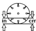
- Set Depth Indicator (GG) (use if desired):
1) Lower machine until diamond blade contacts cutting surface.
2) Set Depth Indicator (GG) dial to align indicator arrows with zero (0). Orange color indicates cutting depth in centimeters. White color indicates inches.
3) Raise saw to maximum height. Now as Diamond Blade (H) is lowered, Depth Indicator (GG) will show cutting depth.
4) Return Diamond Blade (H) to fully raised position.
- Verify that both Emergency Stop Switch (AA) AND Engine Start Switch (DD) are in "ON" position. Emergency Stop Switch (AA) should be in outer position (pulled outward from cowl). Engine Start Switch (DD) must be turned to "1" (ON) position.
- Start Engine. See engine manual for more information.
- Visually verify that tool rotation matches directional arrow on blade guard.
- Open Water Control Valve (KK) FULL open. Verify full water flow, and then adjust for proper amount of water on the blade BEFORE you lower the Blade.
- Make final adjustments to align saw with cutting line. Verify that Guide Wheel (B), and Diamond Blade (H) are both on the cutting line.
If water supply is interrupted, stop cutting immediately. Damage to Diamond Blade (H) could occur.
- Lower Diamond Blade (H) into the cut by slowly turning Blade Depth Control (EE) COUNTER-CLOCKWISE.
- When desired depth of cut is reached, push Blade Depth Stop (FF) down to lock it to Blade Depth Control (EE) (if desired).
- Gently push Rear Handle (JJ) to propel machine forward. Watch Diamond Blade (H) and Guide Wheel (B) carefully to assure that machine stays on cutting line.
- When cut is complete, dis-engage Blade Depth Stop (FF).
- Raise Diamond Blade (H) out of cut by slowly turning Blade Depth Control (EE) CLOCKWISE.
- Close Water Control Valve (KK).
- Turn engine to "0" (OFF) position using the Engine Start Switch (DD).
NOTICE
If an urgent situation arises during cutting operations STOP machine immediately using Emergency Stop Switch (AA).
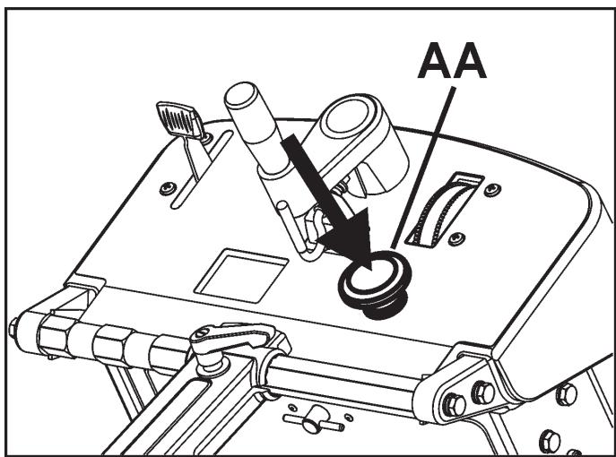

For EMERGENCY STOP of machine, press down EMERGENCY STOP SWITCH (AA).
Before performing any maintenance, ALWAYS park the machine on a level surface with the engine "OFF" and the engine switch set in the "OFF" position. Let the machine cool down! Other maintenance and repairs should only be carried out by a qualified technician.
SERVICE DAILY:
- Check engine oil level.
- Check blade guard for damage.
- Check engine air filter, replace if dirty. Service sooner if used in dusty conditions.
- Clean machine daily.
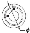
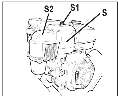
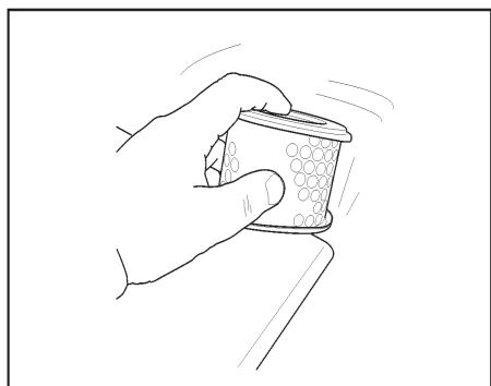
Replacing Engine Air Filter (S):
If the engine seems weak, produces black smoke or runs unevenly, the air filter may be clogged. For this reason, it is important to clean and replace the air filter regularly. Check engine manual for detailed instructions.
Cleaning/replacement of the air filter is carried out as follows:
- Undo the wing nut (S1) and lift off the cyclone air filter cowling (S2).
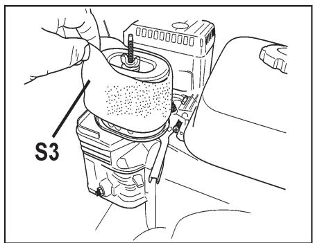
2.Remove the foam rubber pre-filter (S3) and clean using a mild detergent. Squeeze it dry with a clean cloth. Soak it with new engine oil. Squeeze out excess oil.
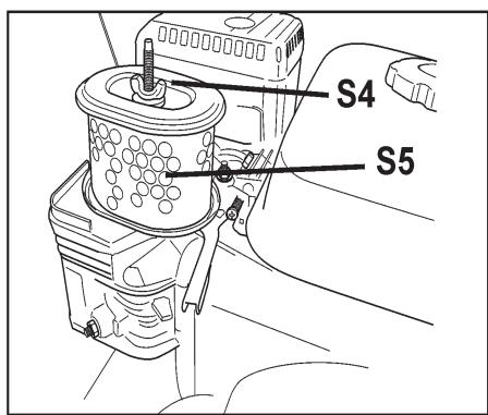
3.Remove the wing nut (S4) in the air filter and remove the paper filter (S5). Tap the paper filter against a fixed surface to remove dust. If the paper filter is still dirty or damaged, it MUST be replaced.
NOTICE
DO NOT use compressed air over 2 bar / 30 PSI to clean the paper filter.
DO NOT wash paper filter.
DO NOT oil paper filter.
- Refit the air filter as follows:
Mount the paper filter in the air filter housing and tighten the wing nut.
5.Refit foam rubber pre-filter (S3) on the paper filter (S5).
6.Refit with the air filter cowling (S2).
SERVICE EVERY 50 HOURS:
- Replace engine oil and filter.
- Clean engine/motor air fins.
- Lubricate Depth Control Grease Fitting (X).
- Check wheels for wear or damage.
- Check blade drive belt tension.
LUBRICATION:
Depth Control Grease Fitting (X): A grease fitting allows lubrication of Blade Depth Control (EE) screw. To access this grease fitting:
- Raise the Diamond Blade (H) to maximum height. Open Tool Compartment (BB), temporarily remove operation manual bag.
- Grease fitting (X) is located near top of Blade Depth Control (EE) Tube.
- Add Grease to the fitting. Raise and lower the machine a few times to circulate the grease through the tube.
- Replace Operation Manual Bag, close Tool Compartment (BB) door.
Engine Oil:
Checking Engine Oil:
Check that engine oil level is correct.
Engine Oil Dipstick (Z) is located on front of engine. Refill engine oil in dipstick hole. When checking oil level, Engine Oil Dipstick (Z) should not be screwed in.
Because engine often operates at an angle, check oil level with engine horizontal. Check frequently to ensure that oil level never falls below lower mark on dipstick. 10W30 oil is recommended.
See engine operation manual for more information.
Changing Engine Oil:
- Turn machine Start Switch (DD) to OFF (0) position. Let engine cool. Use Depth Control (EE) to tilt machine slightly backwards.
- Reposition Oil Drain Hose (NN) to side of machine. Set a suitable container, large enough to hold engine oil capacity, beside machine to catch oil.
- Open end of Oil Drain Hose (NN), and let oil drain into container. After oil is drained, replace Oil Drain Hose (NN) end, tighten securely, return hose to original position.
- Fill engine with recommended quantity of oil - see engine manual for details.
- Dispose of used oil in an environmentally safe manner.

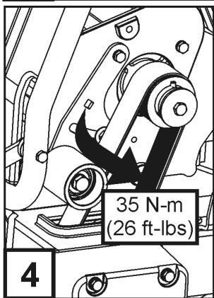
Blade Shaft Drive Belt Tension: Drive Belt should be re-tensioned after first few hours of operation. Belt Drive Idler (MM) holds tension on Drive Belt.
Tools Required:
- 13mm Wrench (Included with machine).
- 3/8" (9.53mm) Drive Torque Wrench (Not Included)
-
14mm Wrench (Not included with machine).
-
Use 13mm Wrench (U), to remove three (3) M8 bolts that attach Belt Guard (LL). Remove Guard (LL).
- Use the 13mm & 14mm wrenches to slightly loosen the two (2) bolts that secure the Belt Drive Idler (MM) [bolts indicated by (2) arrows].
- Attach Torque Wrench to square hole in Belt Drive Idlen (MM).
- Apply a torque to Drive Idler (MM) so that Drive Idler (MM) is forced against the V-Belt. Torque to the value shown in diagram 4.
- Tighten center bolt (CB1) to hold Drive Idler (MM) in position, then tighten remaining bolt (CB2).
- Reinstall Belt Guard (LL). Use 13mm Wrench (U), to tighten three (3) M8 bolts that attach Belt Guard (LL).
Governor Speed
It is critical that Governor and throttle on all internal combustion engines be adjusted properly. Engine speed is preset at factory for proper sawing speed. It is NOT normally necessary to change this setting. It should be periodically verified after machine is placed into service. To change the Governor setting, refer to the engine manual.

WARNING!
Overspeeding Diamond Blade (H) can result in blade breakage and/or personal injury to operator and bystanders! To assure proper Governor adjustment, determine correct blade shaft speed (RPM) from the adjacent chart. Follow engine manufacturer's instruction procedure for Governor and throttle setting.

| Blade Shaft & Engine Speed | ||
| Model | Blade Shaft RPM | Engine RPM |
| FS 413 | 2600 | 3600 |
TROUBLE SHOOTING GUIDE
| Engine Will Not Start: | |
| Cause | Action |
| Electrical switches not in correct position. | Check that BOTH Emergency Stop Switch (AA) and Engine Start Switch (DD) are in “ON” position. Emergency Stop Switch (AA) should be pulled outward from cowl, and Engine Start Switch (DD) turned to “1” (ON) position. |
| Fuel valve closed. | Open the fuel valve. |
| Choke valve open. | Close the choke with cold engine. |
| Fuel tank empty. | Fill with fuel. |
| Contamination, or water ice in fuel system. | Clean tank, fuel lines and carburetor. Fill tank with fresh fuel. |
| Buildup on spark plug electrodes. | Check electrode gap and clean. |
| Engine has no power or runs unevenly. Air filter Clogged. | Clean or replace the air filter. |
| Diamond Blade Trouble Shooting: | |
| Problem | Cause & Action |
| Loss of Tension in Diamond Blade | Blade being used on misaligned saw. Check for proper saw alignment. Blade is excessively "hard" for material being cut, creating stress on steel blade center. Check that blade is correct for material being cut. Different diameter or undersize blade flanges creates uneven pressure on blade center. Use proper size flange on each side of blade. Never use worn or damaged flanges. Blade operated at improper speed (R.P.M.). Make certain blade shaft is turning at the proper speed (R.P.M.) for blade size. Check R.P.M. using a tachometer. Blade improperly mounted on arbor. Could become bent when flanges are tight-ened. |
| Segment Loss | Blade is too "hard" for material being cut. Use "softer" blade specification. Overheated blade, detected as "blue" color on steel center. Check that water supply is adequate and not blocked. Saw is twisted while cutting. Saw only in a straight line. Blade Bore is worn to an eccentric shape (ovalized). Replace worn blade and worn spindle. Segment knocked off during mounting our transport. Avoid rough handling of diamond blade. Never transport the machine with the diamond blade mounted. |
| Cracked Blade Core | Blade is too "hard" for material being cut. Use "softer" blade specification. Overheated blade, detected as "blue" color on steel center. Check that water supply is adequate and not blocked. Saw is twisted while cutting. Saw only in a straight line. |
| WARNING! | |
| DO NOT use damaged diamond blades! Death or injury could occur if machine is operated using damaged diamond blades! | |
| Cracked Blade Segments | Blade is too "hard" for material being cut. Use "softer" blade specification. Blade operated at improper speed (R.P.M.). Make certain blade shaft is turning at the proper speed (R.P.M.) for blade size. Check R.P.M. using a tachometer. |
TECHNICAL DATA
Technical Data - Sound Level, EMC, and HAV
| Sound Level | ||
| MODEL | POWER LEVEL | PRESSURE LEVEL |
| ----- | Lwa (dB) EN 23744 | Lpa (dB) EN ISO 11201 |
| FS 413 | 102.6 | 86.1 |
| - | - | |
EMC (ElectroMagnetic Compatibility)
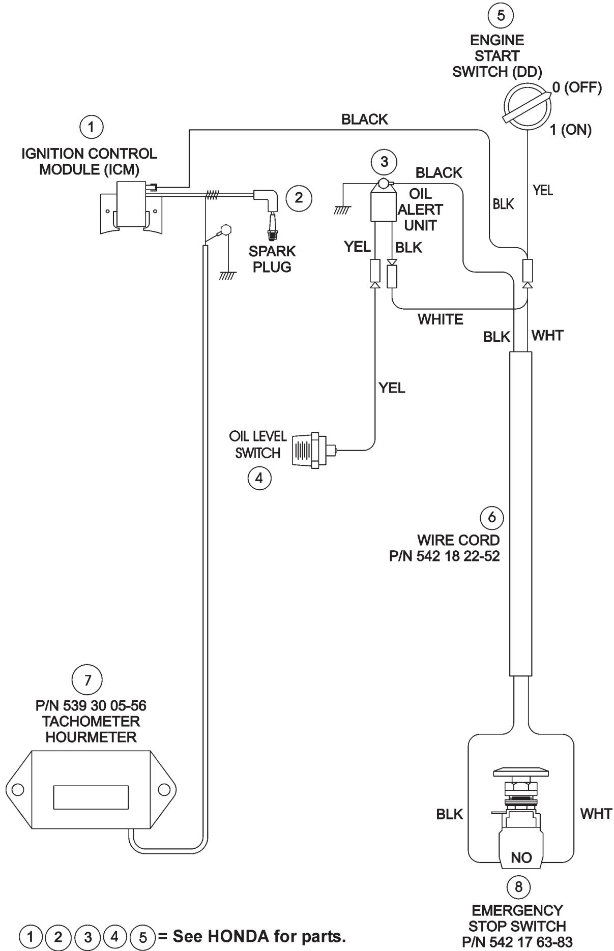
The Honda engine on this equipment has been tested for EMC using the methods outlined in EN 14982:98. The tests found that the engine did not exceed the radiated emission limits. This test report is on file at Husqvarna Construction Products, Olathe, Kansas, USA. Because the engine is the source for a vast majority of Electromagnetic activity of this machine, Husqvarna Construction Products declares the entire machine to be Electromagnetically Compatible.
HAV (Hand-Arm Vibration)
This tool does not exceed the exposure action value of 2.5m / s^2
This equipment has been tested for HAV in accordance with ISO 5349. The results are shown in the following chart.
| Model | Maximum Vibration (Aeq) in m/s2 | Maximum Exposure Time |
| FS413 | 1.64 | +100% |
The Aeq value is the measured continuous vibration at the extended handlebars expressed as acceleration with the units of m / s^2 (meters per second squared). The measured values were taken with a fully warmed engine, running at maximum rated RPM and a 500-mm blade. The measurement point was the grip of the extended handlebars. Instrumentation was a Larson Davis model HVM100 Human Vibration Meter and the SEN021 Triaxial Accelerometer. The accelerometer was secured to a hand adapter, which allows it to sense the same magnitude of vibration as the operator's hand.
The Maximum Exposure Time is a calculated value referenced to an 8-hour workday and the "daily exposure action value" of 2.5m / s^2 as defined in Directive 2002/44/EC of 25 June 2002.
The time weighted daily vibration exposure time can be found with the following formula:
Maximum Exposure Time = (2.5 / Aeq)^2 × 8 hours
Over exposure to vibrations can result in blood vessel or nerve injury to persons suffering with blood circulation problems. Seek medical attention if you experience physical symptoms that can be related to over exposure to vibrations. Examples of symptoms are numbness, lack of feeling, tingling, tickling, pain or a reduction of normal strength, or changes in skin color. These symptoms normally appear in the fingers, hand or wrists.
TECHNICAL DATA
| Machine Mass | ||
| Model | Nominal Mass (kg) | Maximum Mass (kg) |
| FS 413 | 124 | 158 |
| - | - | |
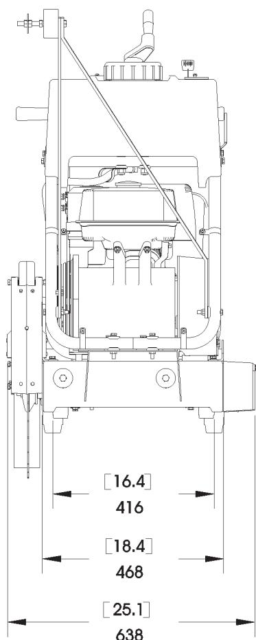
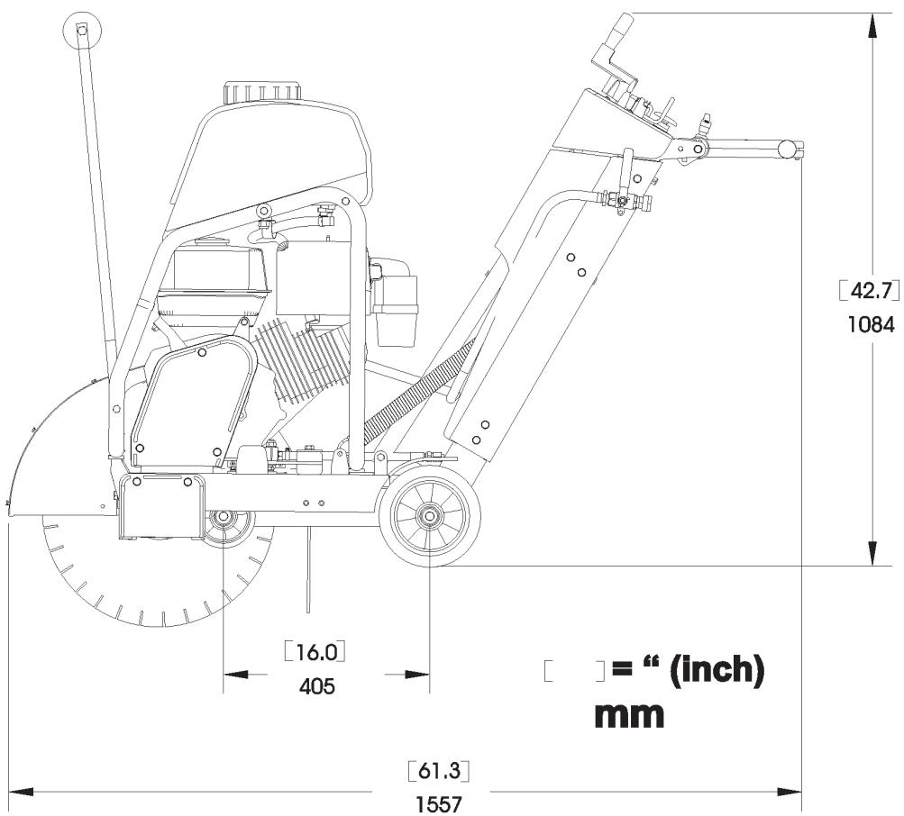
| Cutting Depth | |
| Blade Size | Maximum Blade Cutting Depth |
| 250 mm (10") | 68 mm (2-3/4") |
| 300 mm (12") | 93 mm (3-3/4") |
| 350 mm (14") | 118 mm (4-3/4") |
| 400 mm (16") | 146 mm (5-3/4") |
| 450 mm (18") | 164 mm (6-3/4") |
| 500 mm (20") | 192 mm (7-3/4") |
| Blade Shaft & Engine Speed | ||
| Model | Blade Shaft RPM | Engine RPM |
| FS 413 | 2600 | 3600 |
| Water Tank Capacity |
| 25 Liters (6.6 U.S. Gallons) (5.5 U.K. Gallons) |
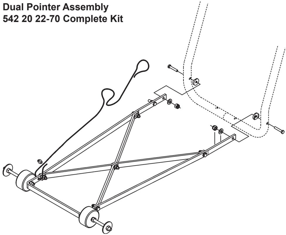
ACCESSORIES
Dual Pointer Assembly 542 20 22-70 Complete Kit
Water Tank Assembly 541 20 82-86 Complete Kit
American National Standards Institute : For units used in the United States, this machine has been designed to comply with American National Standards Institute ANSI B7.1-2000, “Safety Requirements for the Use, Care and Protection of Abrasive Wheels”. This standard can be purchased by contacting the American National Standards Institute at the address shown below:
American National Standards Institute
25 West 43rd Street, 4th floor
New York, NY 10036
Telephone: 212.642.4900
Fax: 212.398.0023
www.ansi.org
CALIFORNIA AIR RESOURCES BOARD (CARB): This machine is considered a preempt Off-Road Application as relating to CARB standards. Under construction equipment, and in particular, as a concrete saw (Saws: concrete, masonry, cutoff), with engine power less than 19KW (25 hp), CARB standards do not apply to this machine.
For more information see the website http://www.arb.ca.gov/msprog/offroad/preempt.htm
EUROPEAN UNION (EU): For units used in countries that are members of the European Union (EU), this machine is designed to meet the EU directives as declared below.

Husqvarna
HUSQVARNA CONSTRUCTION PRODUCTS
DECLARATION OF CONFORMITY WITH THE “SAFETY OF MACHINERY” DIRECTIVE
(Directive 98/37/EC) and the rules governing its transposition
MANUFACTURER
Husqvarna Construction Products North America
17400 West 119th Street, Olathe, Kansas 66061 USA
herewith declares that the machine(s) designed hereunder
FS 413
conforms to the "SAFETY OF MACHINERY" directive (98/37/EC), the "LOW VOLTAGE EQUIPMENT" directive (73/23/EEC), the "ELECTROMAGNETIC COMPATIBILITY" (EMC) directive (89/336/EEC) in accordance with European standards EN 50081/1 and EN 55022, and the "NOISE" directive (2000/14/EEC) in accordance with European standard EN ISO 3744.
Vice President, Operations

26October2006, Olathe, Kansas USA

Husqvarna
Construction Products, North America
Corporate Office
17400 West 119th Street, Olathe, Kansas 66061 USA
Corporate Office: 913-928-1000
Corp. Office Fax: 913-438-7951
www.husqvarna.com
For local service, please contact your local Husqvarna Construction Products representative.
Para efectuar un serviceo local,pongase en contacto con su representante local de Husqvarna Construction Products.
Husqvarna Construction Products
SE-433 81 Partille, Sweden
Tel: +46 31 94 90 00
Fax: +46 31 94 90 50
Asia Pacific:
Husqvarna Construction Products, Australia Pty Ltd
25-31 Kinkaid Avenue,
North Plympton, Adelaide,
South Australia 5037
Tel:+61 (0)8 8375 1000
Fax:+61 (0)8 8371 0990
The Americas:
Husqvarna Construction Products, North America
17400 West 119th Street, Olathe, Kansas 66061 USA
Toll-Free Telephone: 800-288-5040, Telephone: 913-928-1300
Fax: 913-438-7938
CONTENIDO e INTRODUCCION
Contedio
Sección Págrina
Location: Front of Cowl
FS 413
P/N 542 19 07-112
Location: Left and Right Side of Frame
(FS 413 Only)
| For local service, please contact your local Husqvarna Construction Products representative. |
| Para efectuar un servicei local,pongase encontacto con su representante local deHusqvarna Construction Products. |
| Pour toute réparation, contacter le représentantlocal de Husqvarna Construction Products. |
| Für Service vor Ort wenden Sie sichitte anIhren ortlichen Vertreter vonHusqvarna Construction Products. |
| Neem voorplaatselijke service contact op met uwplaatselijke vertegenwoordiger van deconstructionproducten van Husqvarna. |
| Per assistenza, rivolgersi al rappresentante dizone della Husqvarna Construction Products. |
| Für service pa platsen,kontakta din lokalarepresentant für Husqvarna Construction Products. |
| Para obter servicei techniquei local,contactar o representante daHusqvarna Construction Products local. |
| Europa / Europe:HusqvarnaConstruction ProductsSE-433 81 Partille,SwedenTel: +46 31 94 90 00Fax: +46 31 94 90 50 |
| Asia Pacific:HusqvarnaConstruction Products,Australia Pty Ltd25-31 Kinkaid Avenue,North Plymouth,Adelaide,South Australia 5037Tel:+61 (0)8 8375 1000Fax:+61 (0)8 8371 0990 |
| The Americas:Husqvarna Construction Products,North America17400 West 119th Street,Olathe,Kansas 66061 USAToll-Free Telephone:800-288-5040,Telephone:913-928-1300Fax:913-438-7938 |
P/N 542 19 06-46 Local Service Location: Side of Frame
WARNING


Read And Understand Entire Operation Manual Before Operating Machine! Understand AllWarnings, Instructions & Controls Before Operating Machine! Operation Manual Located Within Machine As Shown Below.


P/N 542 19 05-93
Location: Rear of Cowl
WARNING

Fill Tank Only with Water!

DO NOT Fill Tank With Gasoline Or Flammable Liquids! Injury Or Death Could Occur!
P/N 542 19 06-17
Location: Water Tank (If Equipped)
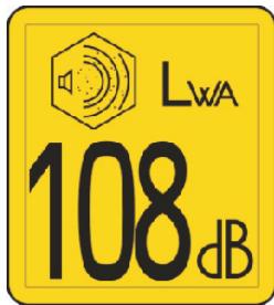
P/N 543 04 57-88 SOUND LEVEL - 108dBA
Location: Blade Guard
WARNING
Muffler Is HOT!
May Cause Burns And / Or Ignition Of Material.
Avoid Contact!
P/N 542 16 90-65 Location: Engine Fuel Tank, Near Muffler

P/N 542 19 06-37
Location: Top of Cowl

P/N 542 19 06-38
Location: Rear of Cowl
Husqvarna Construction Products North America
17400 West 119th Street, Olathe, Kansas 66061 Estados Unidos
NOTAS
IDENTIFICACION DE LAS PIEZAS (QUE ES QUE)
American National Standards Institute
25 West 43rd Street, 4th floor
Fax: 212.398.0023
HUSQVARNA CONSTRUCTION PRODUCTS
Husqvarna Construction Products North America
17400 West 119th Street, Olathe, Kansas 66061 Estados Unidos
Husqvarna Construction Products, North America
Sede Social
17400 West 119th Street, Olathe, Kansas 66061 Estados Unidos
Sede Social: 913-928-1000
Fax de la sede social: 913-438-7951
www.husqvarna.com
Para efectuar un serviceo local,pongase en contacto con su representante local de Husqvarna Construction Products.
Europa / Europe:
Husqvarna Construction Products
SE-433 81 Partille, Sweden
Tel: +46 31 94 90 00
Fax: +46 31 94 90 50
Asia (Pacífico):
Husqvarna Construction Products, Australia Pty Ltd
25-31 Kinkaid Avenue,
North Plympton, Adelaide,
Husqvarna Construction Products, North America
17400 West 119th Street, Olathe, Kansas 66061 Estados Unidos
Location: Front of Cowl
FS 413
P/N 542 19 07-112
Location: Left and Right Side of Frame
(FS 413 Only)
For local service, please contact your local Husqvarna Construction Products representative. Para efectuar un serviceo local,pongase en contacto con su representante local de Husqvarna Construction Products.
contactar o representada duLluvorno Construction Products Local
Husqvarma Construction Products local.
Europa / Europe:
Husqarma
Construction Products
SE-433 81 Partille, Sweden
Tel: +46 31 94 90 00
Fax:+4631949050
Asia Pacific:
Husqvarna
Construction Products,
Australia Pty Ltd
25-31 Kinkaid Avenue
North Plympton, Adelaide
South Australia 5037
Tel: +61 (0)8 8375 1000
Fax:+61(0)883710990
The Americas:
Husqvarna Construction Products,
North America
17400 West 119th Street.
Olathe, Kansas 66061 USA
Toll-Free Telephone: 800-288-5040.
Telephone: 913-928-1300
Fax: 913-438-7938
P/N 542 19 06-46 Local Service Location: Side of Frame

P/N 542 19 05-88
Location: Depth Gauge
WARNING


Read And Understand Entire Operation Manual Before Operating Machine! Understand AllWarnings, Instructions & Controls Before Operating Machine! Operation Manual Located Within Machine As Shown Below.


P/N 542 19 05-93
Location: Rear of Cowl
WARNING

Fill Tank Only with Water!

DO NOT Fill Tank With Gasoline Or Flammable Liquids! Injury Or Death Could Occur!
P/N 542 19 06-17
Location: Water Tank (If Equipped)
WARNING

Muffler Is HOT!
May Cause Burns And / Or Ignition Of Material.
Avoid Contact!
P/N 542 16 90-65 Location: Engine Fuel Tank, Near Muffler
P/N 542 19 06-37
Location: Top of Cowl
WARNING AVERTISSEMENT ADVERTENCIA WARNING WARNING AVERTENZA ATENCAO WAARSCHUWING
Read manua Lea el manu
VouillezireI
IF YOU DO NOT HAVE AN OPE CALL TOLL FREE 1-900-288-50
D. DOD NOT operating No utilization
e manuel. NO dnilar denin
GATOR'S MANUAL 40 (US & Canada)
be near combustible material, such as clear lungs or inflammation.
To be unflgat inimable.
A Machinery Hazard Maquina en funcio
cal. Use only in wet soils. Utilizer epon 1
Always keep all guards in place. Enmiente-Los capotes deben estar
ated areas.
unbenventled
by bin verification
.
.
AEO
40 (USA & Canada).
Vilze 3
empire
protect
1.1.10

LwA
108dB
P/N 543 04 57-88 SOUND LEVEL - 108dBA
Location: Blade Guard
P/N 542 19 06-38
Location: Rear of Cowl
INSTRUCTIONS DE SECURITÉ
Généralités

AVERTISSEMENT!


Alésage: 25,4mm (1,00").

AVERTISSEMENT!
American National Standards Institute
25 West 43rd Street, 4th floor
New York, NY 10036
Telephone: 212.642.4900
Fax: 212.398.0023
www.ansi.org
HUSQVARNA CONSTRUCTION PRODUCTS
Husqvarna Construction Products North America
17400 West 119th Street, Olathe, Kansas 66061 ÉTATS-UNIS
Vice President, Operations
James H. McMenemy
Construction Products, North America
Corporate Office
17400 West 119th Street, Olathe, Kansas 66061 USA
Corporate Office: 913-928-1000
Corp. Office Fax: 913-438-7951
www.husqvarna.com
Husqvarna Construction Products
Husqvarna Construction Products, Australia Pty Ltd
25-31 Kinkaid Avenue,
North Plympton, Adelaide,
South Australia 5037
Tél.: +61 (0)8 8375 1000
Fax +61 0883710990
Amérique :
Husqvarna Construction Products, North America
17400 West 119th Street, Olathe, Kansas 66061 USA
Telephone sans frais : 800-288-5040, Telephone : 913-928-1300
Fax:913-438-7938

Husqvarna
www.husqvarnacp.com
542 20 10-77