
CJ12ex4.3B Series - Lens CANON - Free user manual and instructions
Find the device manual for free CJ12ex4.3B Series CANON in PDF.

| Product Type | BCTV zoom lens |
| Model | CJ12ex4.3B Series (IRSE S, IASE S, IRSE-C S, IASE-C S) |
| Compatible Cameras | B4 mount cameras |
| Focal Length | 1.0x: 4.3-52 mm; 2.0x: 8.6-104 mm |
| Zoom Ratio | 12x |
| Maximum Aperture | 1:1.8 (4.3-40 mm) to 1:2.4 (52 mm) |
| Image Format | Diameter 11 mm (9.6 x 5.4 mm) |
| Angular Field of View | Wide (1x): 96.3° x 64.2°; Tele (1x): 10.5° x 5.9° |
| Minimum Object Distance (M.O.D.) | 0.3 m (macro: 10 mm from lens vertex) |
| Weight (approx.) | IRSE S: 2.10 kg; IASE S: 2.18 kg |
| Power Supply | DC 12 V (10-17 V), max 500 mA |
| Zoom Speed (full range) | Max. 0.5 s ± 0.2 s |
| Focus Speed (full range) | 1.3 s ± 0.3 s |
| Mount Type | B4 |
| Operating Temperature | -20°C to +45°C, 5% to 95% RH (no condensation) |
| Built-in Extender | 2x (mechanical lever) |
| Iris Control | Auto/Manual via camera or lens ring |
| Servo/Manual Zoom | Switchable; clutchless option on -C S models |
| Macro Function | Yes, via macro button and ring (M.O.D. 10 mm) |
| Switch Assignments | VTR, RET, AUX, AUX1, AUX2 (user-configurable) |
| Filter Thread | 127 mm P0.75 (hood) or 94/105 mm P1.0 (barrel) |
| Flange Back | 48 mm (in air) |
| Compliance | FCC Part 15, ICES-3(B)/NMB-3(B), CE (EN55032, EN55103-2) |
| Maintenance | Clean with blower/soft brush; avoid solvents; store with caps |
| Safety Warnings | Do not expose to moisture; avoid staring at sun; secure mounting |
Frequently Asked Questions - CJ12ex4.3B Series CANON
User questions about CJ12ex4.3B Series CANON
0 question about this device. Answer the ones you know or ask your own.
Ask a new question about this device
Download the instructions for your Lens in PDF format for free! Find your manual CJ12ex4.3B Series - CANON and take your electronic device back in hand. On this page are published all the documents necessary for the use of your device. CJ12ex4.3B Series by CANON.
USER MANUAL CJ12ex4.3B Series CANON
Read this operation manual before using the product.
Keep the manual in place for future reference.
| CJ12ex4.3B | IRSE S |
| IASE S IASE-C S | |
| IRSE-C S | |
| IASE-C S |
| CJ20ex7.8B | IASE S |
①アイリスゲイン調整トリマー
②アイリス瞬時オートスイッチ
③アイリス動作モード切替えスイッチ
④ ズームシーソースイッチ
⑤RETスイッチ
⑥ MEMOスイッチ
⑦AUXスイッチ
①ディスプレイスイッチ
| スイッチ | デフォルト | 割付け可能な機能 | |||||||||
| Fr1P | Fr1F | Fr2P | Fr2F | Sped | Shl | NON | VTR | RET | |||
| 1 V VTR | ● | ● | ● | ● | ● | ● | ● | ||||
| 2 R RET | ● | ● | ● | ● | ● | ● | ● | ||||
| 3 A Fr1P | ● | ● | ● | ● | ● | ● | ● | ● | |||
| 4 A1 | Shtl | ● | ● | ● | ● | ● | ● | ● | ● | ||
| 5 A2 | Fr1P | ● | ● | ● | ● | ● | ● | ● | ● | ||
The English version is the operation manual for counties other than Japan.
FCC REGULATIONS
This device complies with Part 15 of the FCC Rules. Operation is subject to the following two conditions: (1) This device may not cause harmful interference, and (2) this device must accept any interference received, including interference that may cause undesired operation.
Note: This equipment has been tested and found to comply with the limits for a Class B digital device, pursuant to Part 15 of the FCC Rules. These limits are designed to provide reasonable protection against harmful interference in a residential installation. This equipment generates, uses and can radiate radio frequency energy and, if not installed and used in accordance with the instructions, may cause harmful interference to radio communications. However, there is no guarantee that interference will not occur in a particular installation. If this equipment does cause harmful interference to radio or television reception, which can be determined by turning the equipment off and on, the user is encouraged to try to correct the interference by one or more of the following measures:
-- Reorient or relocate the receiving antenna.
-- Increase the separation between the equipment and receiver.
-- Connect the equipment into an outlet on a circuit different from that to which the receiver is connected.
-- Consult the dealer or an experienced radio/TV technician for help.
Do not make any changes or modifications to the equipment unless otherwise specified in the manual. If such changes or modifications should be made, you could be required to stop operation of the equipment.
Canadian Radio Interference Regulations
CAN ICES-3(B)/NMB-3(B)
CE
We, Canon Inc., in Japan and CANON EUROPE LTD., in U.K., confirm that the BCTV zoom lens is conformity with the essential requirements of EC Directive(s) by applying the following standards:
EN55032 and EN55103-2
Note:
a) Applicable Electromagnetic Environments:
E1 (residential), E2 (commercial and light industrial), E3 (urban outdoors) and E4 (controlled EMC environment, ex. TV studio).
b) Use of shielded cable is required to comply with limits specified by above standards.
Only for European Union and EEA (Norway, Iceland, and Liechtenstein)

This symbol indicates that this product is not to be disposed of with your household waste, according to the WEEE Directive (2012/19/EU) and national legislation. This product should be handed over to a designated collection point, e.g., on an authorized one-for-one basis when you buy a new similar product or to an authorized collection site for recycling waste electrical and electronic equipment (EEE). Improper handling of this type of waste could have a possible negative impact on the environment and human health due to potentially hazardous substances that are generally associated with EEE. At the same time, your cooperation in the correct disposal of this product will contribute to the effective usage of natural resources. For more information
about where you can drop off your waste equipment for recycling, please contact your local city office, waste authority, approved WEEE scheme or your household waste disposal service.
For more information regarding return and recycling of WEEE products, please visit
www.canon-europe.com/weee.
- FOREWORD -
Thank you for purchasing the Canon BCTV zoom lens.
This product comes with the following documents for the models mentioned below:
①Operation Manual "Lens"
②Operation Manual "Information Display CD-ROM"
| CJ12ex4.3B | IRSE S CJ20ex7.8B IASE S | |
| IASE S | ||
| IRSE-C S | ||
| IASE-C S |
The illustrations in this book show CJ12ex4.3B.
Actual forms may vary depending on models and specifications.
STANDARD PRODUCT LIST
Make sure all of the following items are included in the packing box. If you find any item missing, please contact your dealer or Canon Inc.
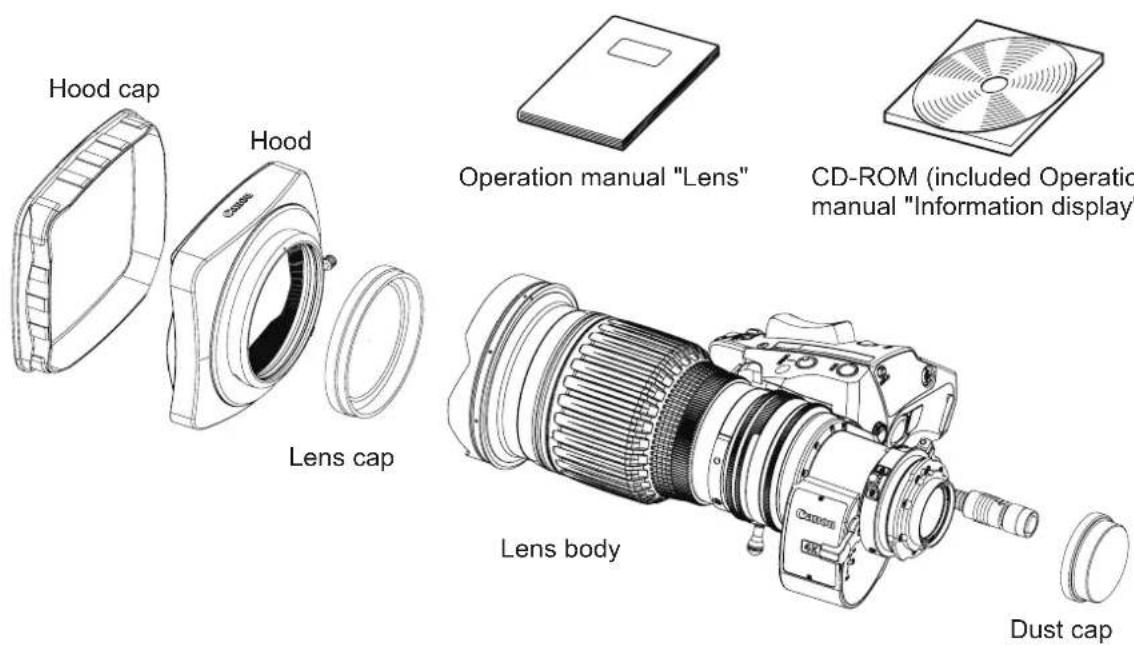
Accessories other than those mentioned above may be required depending on the specifications of your unit. For details, contact your dealer or Canon Inc.

GENERAL SAFETY INFORMATION
The safety warnings and cautions provided on the product or in this operation manual must be observed.
Failure to observe these warnings and cautions may result in injury or accident.
Read this operation manual carefully to familiarize yourself with its contents and ensure that you can operate the product properly.
Also, store this manual in a safe place where it can easily be referenced whenever necessary.
This operation manual uses the following symbols and terms to identify hazards in order to prevent accidents.
| WARNING | This indicates a potentially hazardous situation which, if not heeded, may result in death or serious injury to you or others. Be sure to heed all warning notices to ensure safe operation at all times. |
| CAUTION | This indicates a potentially hazardous situation which, if not heeded, may result in a minor injury to you or others, or damage to property. |
| NOTE | This indicates cautions and recommendations for operation. It contains information which, if not heeded, may result in this product failing to function properly. These notices also contain useful information for operation. |
HANDLING THE PRODUCT

WARNING
- Do not get this product wet or allow liquid inside. If water gets inside, stop using the product immediately. Continuing to use the product under this condition may cause a fire or electric shocks.
- Do not stare at the sun or other bright objects through the lens. It may injure your eyes.
- Be sure to hold the connector when disconnecting the cable. Pulling on the cable may sever or damage it and pose a risk of a fire or electric shocks from a short circuit.

CAUTION
- Be careful not to drop the product when carrying it. Dropping the product may cause injury.
- Ensure that all mountings are securely tightened. If a mounting becomes loose, parts may fall off and cause injury.
- Inspect mountings regularly (about every six months to one year) to ensure they are securely tightened. If a mounting becomes loose, parts may fall off and cause injury.
- When this product is used under a blazing sun, the inside of the unit may be heated to high temperature. When it is expected that the unit is exposed to elevated temperature, take measures against heat as appropriate on the customer's side.
NOTE
- When service is required, contact your dealer or Canon's representative.
- Striking or dropping the lens may cause the malfunction of the product.
- This product is not waterproof. Take measures to avoid direct contact with rain, snow, or moisture. Otherwise it may cause the malfunction of the product.
- In dusty environments, cover the lens mount when using, attaching or removing the lens. If dust enters inside, it may cause the malfunction of the product.
- Take measures to avoid sudden changes in temperature where the lens is used, which may prevent operation temporarily if condensation forms in the lens.
- Before use in particular environments, such as places where chemical products are used, contact your Canon representative.
DEALING WITH ABNORMALITIES

WARNING
Should any of the abnormalities described below occur, immediately dismount the lens from the camera and contact Canon's representative or the dealer listed below.
- Smoke, fumes, or unusual noises
- Entry of foreign objects (such as liquid or metal objects) inside the product
MAINTENANCE AND INSPECTION

WARNING
Be sure to disconnect the cable and remove the lens from the camera before cleaning outside of the lens. Do not use benzene, thinner, or other flammable substances to clean the product. Otherwise it may cause a fire or electric shocks.
NOTE
- Clean off any dust on the lens surface using a lens blower or a soft lens brush. In case of getting fingerprints or stains on the lens, use a clean cotton cloth moistened with commercial lens cleaning fluid, or use lens cleaning paper. Gently wipe in a spiral pattern from the center of the lens. Be careful not to rub dust across the lens, which may scratch the lens surface
- Routine inspection about once a year is recommended, depending on the conditions and environment of use. Request overhaul, if needed.
STORAGE

CAUTION
Always attach the lens cap, hood cap, dust cap or covers before storage. Storing the lens without the caps or covers attached poses a risk of fire if the lens concentrate light in direct sunlight.
NOTE
Immediately wipe off any moisture on the lens from misty or foggy environments, using a dry cloth. Seal the lens in a plastic bag with a desiccant (preferably new) to prevent moisture inside. Otherwise it may cause the mold or the malfunction of the product.
TO THE CUSTOMER
- Canon shall bear no responsibility for damage resulting from improper operation of this product by the customer.
- Canon shall make no guarantees about the product quality, functions, or operation manual and its marketability and suitability for the customer's purpose.
Moreover, Canon shall bear no responsibility for any damage, direct or incidental, that results from usage for the customer's purpose. - Canon shall make no guarantees about the results obtained using this product.
- The product specifications, configuration, and appearance are subject to change without price.
- For further information on repairs, maintenance, or adjustments not mentioned in this operation manual, contact your Canon dealer or your Canon sales representative.
- Note that Canon may be unable to undertake servicing or repair of a product if it is modified without consulting Canon or your Canon sales representative.
CANON INC.
30-2, Shimomaruko 3-chome, Ohta-ku, Tokyo
146-8501, Japan
Canon Europe Ltd
3 The Square, Stockley Park, Uxbridge, Middlesex, UB11 1ET UK
The copyright for this manual is retained by Canon Inc.
Unauthorized copying or reproduction in whole or part is prohibited.
| 1 NOMENCLATURE | E2 | ||
| 2 HOW TO MOUNT | 2-1. MOUNT THE LENS ON THE CAMERA2-2. MOUNT THE HOOD ON THE LENS2-3. TURN IT ON | E3 | |
| 3 ADJUSTMENT | 3-1. BACK FOCUS ADJUSTMENT OF THE LENS3-2. IRIS GAIN ADJUSTMENT | E4 | |
| 4 MODE SETTING | 4-1. OPERATION MODES4-2. SETTING ITEMS IN BASIC MODE4-3. SETTING ITEMS IN FULL MODE4-4. SETTING ITEMS IN ANALOG MODE | E5 | |
| 5 OPERATION | 5-1. ZOOM OPERATION5-2. FOCUS OPERATION5-3. EXTENDER OPERATION5-4. IRIS OPERATION5-5. MACRO OPERATION5-6. SWITCH OPERATIONS | E7 | |
| 6 PRODUCT SPECIFICATIONS | E15 | ||
| APPENDIXES | TECHNICAL INFORMATION INDEX | END |
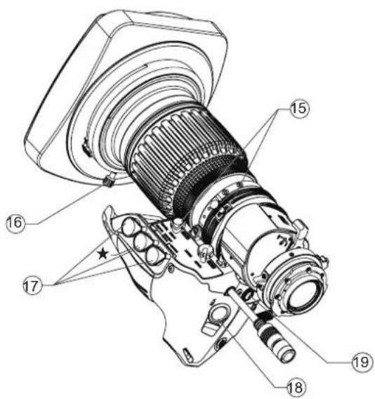
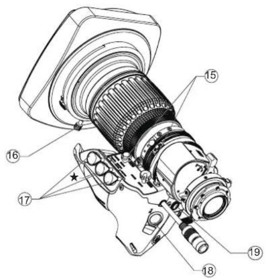
1 NOMENCLATURE
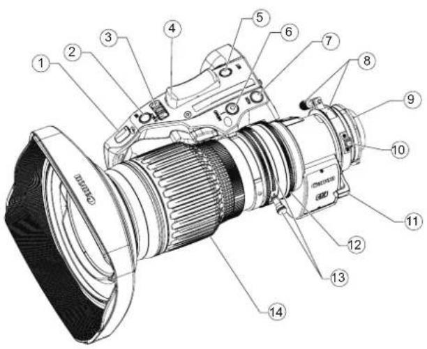
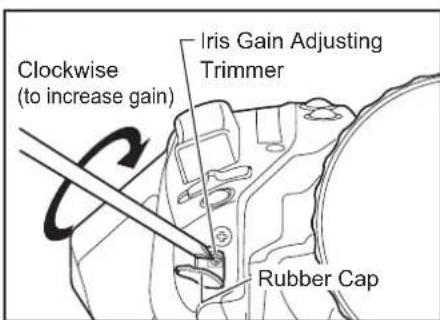
① Iris Gain Adjusting Trimmer
② Instant Auto-Iris Switch
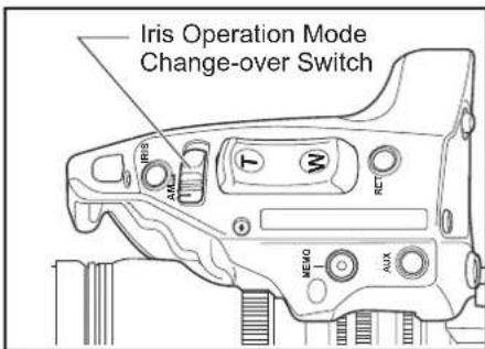
③ Iris Operation Mode Change-over Switch
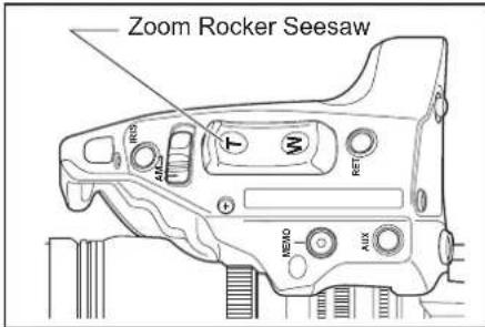
④ Zoom Rocker Seesaw
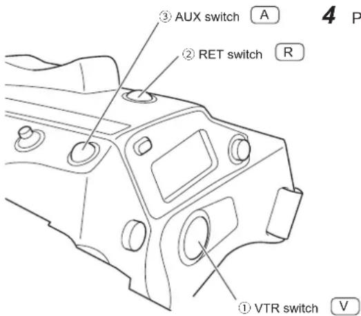
⑤ RET Switch (Video Return Switch)
⑥ Memo Switch (Memory Switch)
⑦ AUX Swich
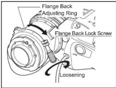
⑧ Flange Back Lock Screw/Flange Back Adjusting Ring
⑨ Locating Pin
⑩ Macro Button/Macro Ring
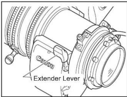
⑪ Extender Lever
⑫ Iris Ring
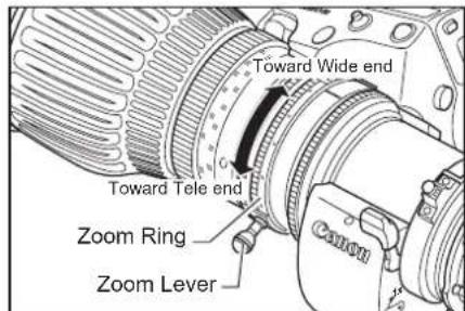
⑬ Zoom Lever/Zoom Ring
⑭ Focus Ring
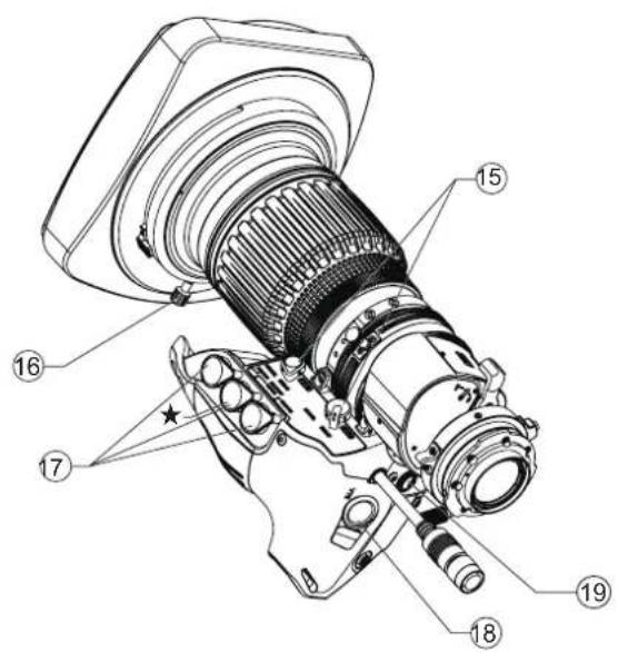
⑮ Zoom/Focus* Operation Change-over Knob
NOTE) *IASE S and IASE-C S type lenses only.
⑯ Hood Lock Knob
⑰ Zoom/Focus Remote Virtual Connectors (20-pin)
NOTE) Virtual output port is Connector ★ only.
Use these connectors to connect the control accessory (equipped with a 20 pin connector) for zooming or focusing. Connector ★ is also used to connect to the interface of such as virtual system. It can output each positioning signal of zoom, focus, and iris.
⑱ VTR Switch
⑲ Max. Zoom Speed Adjusting Volume
Information Display (Digital Drive Unit)
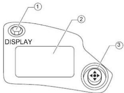
① Display Switch
Used to turn the display ON/OFF.
② Display
It turns off if left for 2 minutes without operation.
③ Control key
Used to move the cursor up/down/left/right. Press the center to confirm.
For the operation of the digital drive unit, refer to the "Information Display Manual" on the CD-ROM.
2 HOW TO MOUNT
2-1. MOUNT THE LENS ON THE CAMERA
Before mounting the lens on the camera, make sure that the camera's power is turned off.
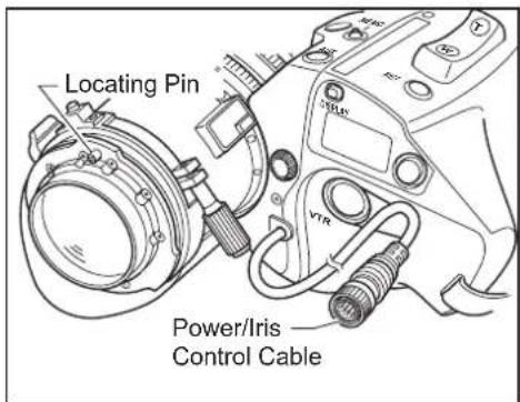
1 Remove the dust cap from the lens.
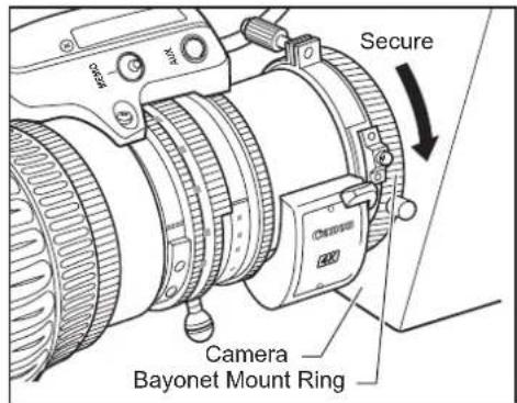
2 Align the lens locating pin to the groove on the camera mount to fit the lens to the camera mount.
3 Turn the bayonet mount ring on the camera to secure the lens.
4 Connect the power/iris control cable of the lens to the camera.
NOTE
- Never hold the lens, drive unit and band portion to support the entire weight of the camera. Excessive force to the mount portion and drive unit of the lens may result in damage to the lens mechanism.
- Rated voltage: 12 VDC Normal operation range: 10 to 17 VDC If a battery or adapter is used, the output voltage may be higher than the rated voltage depending on the manufacturers and therefore the above voltages must be observed strictly. If a voltage outside the normal operation range is used, the drive unit may be damaged. And the lens power input has the positive and negative polarities. Make sure to connect the power cable to the correct polarity when connecting the batteries or the adaptors. Connecting the cable to the incorrect polarity may cause the damage to the product.
2-2. MOUNT THE HOOD ON THE LENS
The lens cap is attached to the lens at the factory. Please remove the lens cap before mounting the hood.
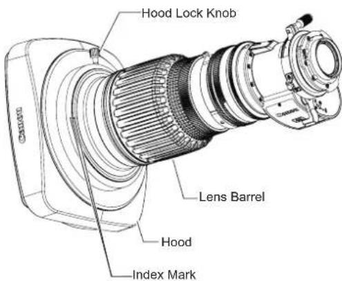
1 Fit the hood on the front of the lens barrel.
2 Align the index marks on the hood and lens barrel.
3 Tighten the hood lock knob.
2-3. TURN IT ON
Turn on the camera, and the power of the lens will be supplied.
3 ADJUSTMENT
3-1. BACK FOCUS ADJUSTMENT
If the relationship between the image plane of the lens and the image plane of the television camera is incorrect, the object goes out of focus when the lens is zoomed. Follow the procedure below to adjust the back focus of the lens.
1 Select an object at an appropriate distance (CJ12ex4.3B : approx. 1 to 3m, CJ20ex7.8B : approx. 2 to 5m recommended). Use any object with sharp contrast to facilitate the adjustment work.
2 Set the extender lever to 1x.
3 Set the iris fully open.
4 Set the lens to the telephoto angle by turning the zoom ring.
5 Bring the object into focus by turning the focus ring.
6 Set the lens to the widest angle by turning the zoom ring.
7 Loosen the flange back lock screw, and turn the flange back adjusting ring to bring the object into focus.
8 Repeat steps 4 to 7 a few times until the object is brought into focus both at the widest end and the telephoto end.
9 Tighten the flange back lock screw.
3-2. IRIS GAIN ADJUSTMENT
An iris gain adjusting trimmer is located on the front of the lens drive unit. The iris gain is set at middle of range at the factory. However, if you wish to change the iris gain, adjust the trimmer using a small screwdriver.
1 Pull up the rubber cap on the iris gain adjusting trimmer.
2 Set the iris operation mode change-over switch to the "A" (Auto) position.
3 Turn the iris gain adjusting trimmer, using a small screwdriver. As you look at the lens iris ring, set it to the position of maximum gain at which no iris hunting occurs.
4 Close the rubber cap after adjustment completes.
This adjustment can be performed on the information display. Refer to the Information Display Manual.
4 MODE SETTING
There are three operation modes below. One of the operation modes can be selected on the display screen of the information display of this lens according to usage and preference.
- Basic mode : Items that can be set and viewed are limited in this mode, and are recommended to users who do not require sophisticated settings. This product is factory-set to basic mode.
- Full mode : All items can be set and viewed in this mode.
-
Analog mode : This mode is selected when the digital functions are not used at all.
-
Switches labeled VTR, RET, IRIS A/M, and IRIS INST control the respective functions. The rocker switch serves as a regular zoom switch.
- AUX and MEMO switches are disabled.
- To set auto iris gain adjustment, use either display or trimmer operations.
- Shuttle shot, frame preset, speed preset, and zoom tracking are not available.
This manual describes only the items that can be set on the Top screen in each mode.
For details on how to set them, refer to the "Information Display Manual" on the supplied CD-ROM.
4-2. SETTING ITEMS IN BASIC MODE
The following eight items can be set on the top screen in Basic Mode.
![Initial Top screen in Basic Mode MENU IG: 50 A Fr1P [Trk] OFF A1 Shtl A2 Fr1P [I-Tq]H [Z.M.]](/content/2026/05/793037/images/a48800a2e3e7e6f5668342030101b6a89b330a5aaf5e7789fccdc69228a8f9a0.jpg)
- Go to MENU screen
- Auto iris gain settings
- AUX switch assignment
- Zoom tracking ON/OFF
- AUX1 switch assignment
- AUX2 switch assignment
- Iris torque settings
- Zoom curve mode settings
For details on how to set each setting item, refer to "Information Display Manual" on the supplied CD-ROM.
4-3. SETTING ITEMS IN FULL MODE
The following 14 items can be set on the top screen in Full Mode.
![Initial Top screen in Full Mode MENU [ Basic ] 1 [ Trk] OFF A Fr1P [ I-Gain ] A 1 Shtl VTR](/content/2026/05/793037/images/e84103b6de315bc4daddef154545af926512a802dfd46595aaa95f72811f5a1e.jpg)
![Items not scrolled MENU [1] 1 A2 Fr1P R RET [ Z.M. ] AM Norm Zoom Items displayed by scrolling](/content/2026/05/793037/images/285c98f64283316a10849d07cbee87ca5069e90bdf6d06fc3587eaa91fff727b.jpg)
- Go to MENU screen
- Switch users
- Switch to Basic Mode
- Zoom tracking ON/OFF
- AUX switch assignment
- Iris gain settings
- AUX1 switch assignment
- VTR switch assignment
- AUX2 switch assignment
- RET switch assignment
- Iris torque settings
- Zoom curve mode settings
- Iris A/M switch setting
- Seasaw switch assignment
4-4. SETTING ITEMS IN ANALOG MODE
The following three items can be set on the top screen in Analog Mode.
![Initial Top screen in Analog Mode MENU → IG: 50 [ Basic ]](/content/2026/05/793037/images/229c774a773c1e24d48d0a44cab683e91866e1065caf1ca268ec8ccbfa0d5461.jpg)
- Go to MENU screen
- Auto iris gain settings
- Switch to Basic Mode
For details on how to set each setting item, refer to "Information Display Manual" on the supplied CD-ROM.
5 OPERATION
5-1. ZOOM OPERATION
5-1-1. Manual Zoom Operation
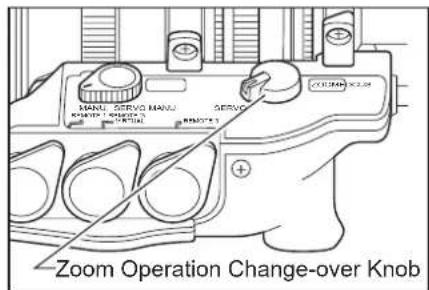
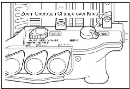
1 Set the zoom operation change-over knob at the bottom of the lens drive unit to MANU. position.
2 Turn the zoom ring (or zoom lever) to perform zoom operation.
NOTE
The zoom operation change-over knob must be set to the "MANU." position before performing manual zoom operations.
The lens may be damaged if manual zoom operations are forcibly performed with the knob at the "SERVO" position.
5-1-2. Servo Zoom Operation
Zoom operation can be performed by driving the built-in motor in the lens.
1 Set the zoom operation change-over knob to SERVO position.
2 Press the zoom rocker seesaw to perform zoom operation. Zoom speed changes by the depth of the switch being pressed. The deeper the switch is pressed the faster the zoom speed.
5-1-3. Maximum Zoom Speed Adjustment
The maximum speed of zoom when the zoom rocker seesaw is pressed can be adjusted with the adjusting volume.
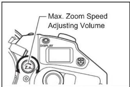
This adjustment can be performed on the information display. Refer to the Information Display Manual.
5-1-4. Zoom Track Function (only for servo zoom)
The zoom control range (zoom track) position can be set as desired to set the virtual zoom limit in the telephoto end and the widest angle end. To use the zoom track function, the function should be enabled in advance.
A : Setting "ON" or "OFF" on the information display (In case of basic mode)
![MENU IG:50 A Fr1P [Trk] OFF A 1 A3htl Fr1P [ H I-Tq ][ Z.M.](/content/2026/05/793037/images/a80bef68e538d85b8c8eb2ace5fbbe065b2e306e4a3c6c630eab0520f8b60536.jpg)
1 Press the DISPLAY switch to turn on the display.
2 Select [Trk] using the control key, and then press the Set key. [Trk] and the previous setting now blink on the display.
3 Press the left or right key to select ON or OFF.
4 Press the Set key. This completes the setting.
For details, refer to the Information Display Operation Manual.
B: Setting "ON" or "OFF" by operating the switches
| Selection method | Operation | How to ascertain the selection | |
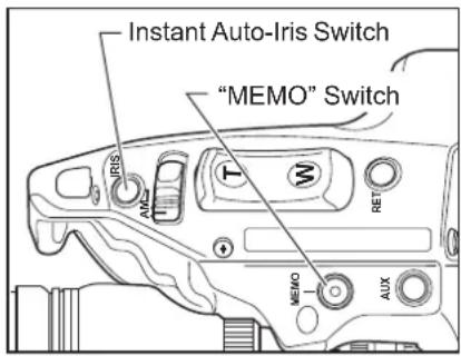
| To set the function to "ON" | Hold down MEMO botton and Instant auto-iris switch simultaneously for at least 3 seconds. | The zoom control range is fixed to the zoom range set last. (If there is no previous setting, it is set to the mechanism end point.) | Automatic zooming from current zoom position to the closer of the two set positions. |
| To set the function to "OFF" | The zoom range is set to the mechanical end. | Automatic zooming from current zoom position to the closer of the two mechanical ends. |
Setting the Zoom Track Positions
Set the zoom track function to ON before setting the zoom track position.
1 Zoom to the zoom track position that you want to set.
2 Keeping this zoom position, press the Instant Auto-Iris switch while holding down the MEMO switch. If the zoom position is at the tele-photo end, the position is stored as the zoom track position for the telephoto limit. If position is at the widest angle end, it is stored as the widest limit.
3 Repeat step 1 and 2 to set both the telephoto and the widest limits. It is possible to set only one end. To change the setting, perform step 1 to 3. (The position set last overwrites the setting in the memory.)
1) If the zoom track position is to be set again, the zoom position cannot move beyond the end point setting toward the mechanical end by performing servo zoom operations. To move the zoom, set the zoom track function to OFF, then take one of the steps below.
- Proceed with the zooming operation at the setting established by operating the zoom rocker seesaw.
- Perform the zooming operation manually.
2) Although up to two zoom track positions (the telephoto end and the widest angle end) can be set, two positions cannot be set that are on the same side of the center position of the zoom range of this lens. (In this case, the latest setting is stored as the zoom track position of this side.)
5-1-5. Shuttle-Shot Function
This function allows you to switch between the current zoom position and the preset zoom position at the maximum speed.

speed
Current zoom position Shuttle memory position Previous zoom position
Before using shuttle-shot function, the shuttle function must be assigned to the VTR, RET, or AUX switch of the drive unit, or the AUX1 or AUX2 switch on the zoom demand. This manual describes the "Shtl" function assigned to the VTR switch. For details, refer to "5-6 SWITCH OPERATIONS".
Setting the shuttle memory position
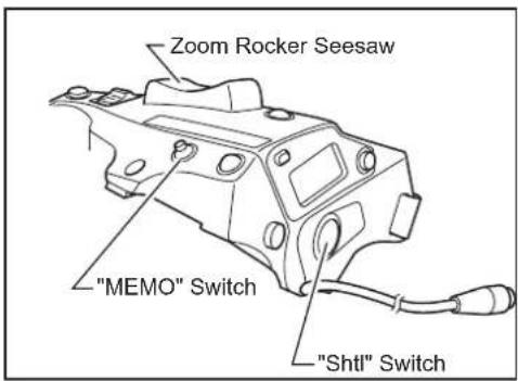
Zoom to the position that you want to store. Keeping this position, press the Shtl switch while holding down the MEMO switch.
The "position" you stored here is different from the one you set in "Framing Preset" mentioned later. The stored position set here is retained even after the power is turned off.
The operation with the Shtl switch is given the priority over that with the zoom rocker seesaw. The operation with the zoom rocker seesaw is disabled while the Shtl switch is pressed.
5-1-6. Speed Preset
This function allows you to call the preset zoom speed any time you zoom. Assign the "Sped" function to the VTR, RET, or AUX switch of the drive unit, or AUX1 or AUX2 switch on the zoom demand. This manual describes the "Sped" function assigned to the VTR switch.
- Storing the zoom speed and direction
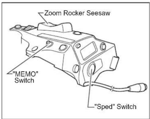
Operate the zoom rocker seesaw to determine the zoom speed and direction (toward the telephoto angle or the widest angle) which you want to store, and press the MEMO switch while holding this position.
The stored zoom speed is applied to the "Framing Preset".
2. How to operate the speed preset function
When the "Sped" switch is pressed, the zoom starts to move at the preset speed and to the determined direction (toward the telephoto angle or the widest angle) stored in section 1 and stops at the zoom end.
3. How to cancel movement in Speed Preset
Movement in Speed Preset can be canceled by any of the following operations.
1) Press the "Sped" switch again.→ Zooming stops.
2) Performing zoom operation with the zoom rocker seasaw / "Shtl" switch / "Fr1P" switch / "Fr2P" switch / "Fr1F" switch / "Fr2F" switch.
5-1-7. Framing Preset
There are three framing preset types based on how the settings are combined.
[Zoom]
This enables a predetermined picture angle and movement speed (zoom speed) to be reproduced easily.
[Focus] "IASE S/IASE-C S" type only
This enables a predetermined focus to be reproduced easily.
[Z+F] "IASE S/IASE-C S" type only
This enables the movement speed (focus speed, zoom speed) to a predetermined focus and picture angle to be reproduced easily.
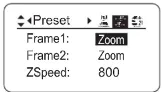
The framing preset setting is changed on the Preset screen on the information display. The "Frame1" setting is changed to "Zoom", "Focus", or "Z+F".
Up to two framing presets, Frame1 and Frame2, can be stored in the memory. Only Frame1 is described in the description given on the following pages. Frame1 is indicated as Fr1P".
How to set the zoom speed to the framing memory position
Movement speed to the framing position is selected by assigning the "Fr1P" or "Fr1F" switch.
"Fr1P"----For the preset speed setting (preset speed) (Assigned to the AUX switch at the factory.)
"Fr1F"----For the maximum speed setting (fast speed)
For details on how to assign the switches, refer to 5-6. SWITCH OPERATIONS.
Setting combinations
| Frame preset control | Control content | Movement speed setting | |
| "Fr1P", "Fr2P"(speed settable) | "Fr1F", "Fr2F"(maximum speed) | ||
| Zoom | Zoom operation control | The zoom moves at the preset speed. | The zoom moves at the maximum speed. |
| Focus | Focus operation control | *1The focus moves at maximum speed. | The focus moves at maximum speed. |
| Z+F | Zoom + focus operation control | *2The zoom and focus move at the preset speeds. | The zoom and focus move at the maximum speed. |
*1 : Focus speed is fixed at maximum speed.
*2: The zoom and focus are controlled in such a way that they start and stop simultaneously.
Framing Preset [Zoom]/[Focus]/[Z+F] Setting
The following figure below is shown as an example. Actual state of the switch may look different if the function is allocated to the different switch.
1) Fr1P function----Assigned to the AUX switch by factory default.
1. Setting the framing memory position
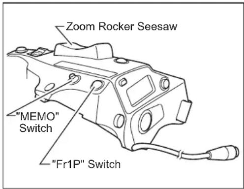
Zoom (and focus) to the position that you want to store, while holding this zoom (and zoom focus) position, press the "Fr1P" switchwhile holding down the MEMO switch.
This framing memory position is different from the shuttle memory position (Refer to "5-1-5. Shuttle-Shot Function"). The stored zoom position remains in the memory, even after the power is turned off.
2. Moving to the framing memory position
Once the "Fr1P" switch is pressed, the zoom starts to move toward the framing memory position at the preset speed and stops at the framing memory position. When the zoom reaches to the framing memory position, it stops and stays there.
3. Canceling the movement to the framing memory position or switching to other zoom operation
During movement to the framing memory position, the movement can be canceled and/or switched to other zoom operation by any of the following operations.
[Zoom Framing Preset]
- Press the "Fr1P" switch again.
- Perform zoom operation with the zoom rocker see-saw.
- Per rf or m zo om o per a ti on w it h th "eSh tl" switch.
[Focus Framing Preset]
[Zoom, Focus Framing Preset]
- Operate a connected focus demand. Movement to the memory position stops, and movement to the operating position of the focus demand takes place.
5-1-8 Clutchless Zoom ('-C S"LENS only)
The "-C S" lens clutchless incorporates a clutchless zoom mechanism.
Owing to the clutchless zoom mechanism, you are no longer required to operate the clutch when switching between the servo zoom and manual zoom. This mechanism allows you to use a slow steady servo zoom technique in the MANUAL mode.
Set the zoom operation change-over knob to the SERVO position to activate the clutchless zoom mechanism.
NOTE
The lens may be damaged if manual zoom operation is performed during the servo zoom operation.
| Zoom operation change-over knob | Clutchless zoom mechanism | Operation |
| SERVO ON | Setting used when both servo and manual operations are needed Without operating a clutch, you can switch between the servo zoom and manual zoom. | |
| MANU. OFF Set to MANU. when using only the manual zoom. | ||
1 When IASE S or IASE-C S type lens is used, set the focus operation change-over knob to MANU. position.
When using the IASE S or IASE-C S type lens, the camera can be damaged if excessive force is used to try to turn the focus ring when the knob is left in the SERVO position.
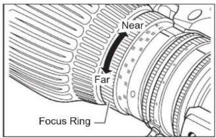
2 Turn the focus ring to bring the near or far object into focus.
5-2-2. Servo Focus Operation
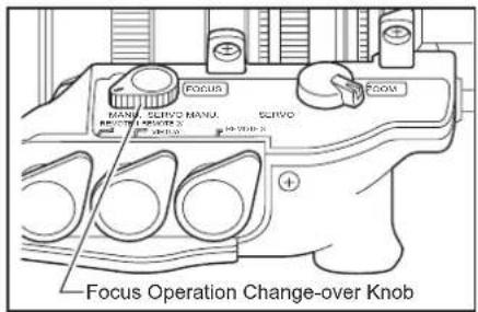
1 When IASE S or IASE-C S type lens is used, set the focus operation change-over knob to SERVO position.
2 Mount the accessory such as focus demand. For the details, refer to the operation manual of accessories.
The lens with built-in extender has the built-in 2x extender.
Use the extender lever to switch between 1x and 2x.
When the extender is used, note that the light quantity may decrease by the zoom ratio depending on the iris correction setting.
5-4. IRIS OPERATION
The iris operation mode can be switched between auto and manual with the iris operation mode change-over switch.
5-4-1. Automatic Iris Operation
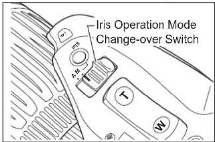
Slide the iris operation mode change-over switch to the "A" position. The iris operation is performed automatically by the instruction from the camera, to keep the video signal level constant.
5-4-2. Manual Iris Operation
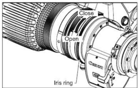
Slide the iris operation mode change-over switch to the "M" position. The iris operation is performed by turning the iris ring on the lens body.
NOTE
The iris operation mode change-over switch must be set to the M position before performing manual iris operations. The lens may be damaged if manual iris operations are forcibly performed with the knob at the A position.
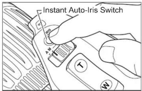
When the instant auto-iris switch is pressed during manual iris operation mode, the iris changes to automatic operation mode while the switch is held down.
This adjustment can be performed on the information display. Refer to the Information Display Manual.
In macro shooting, the object distance becomes shorter than the normal minimum object distance (M.O.D.). The minimum object distance by macro operation for this lens is 10mm at the widest angle.
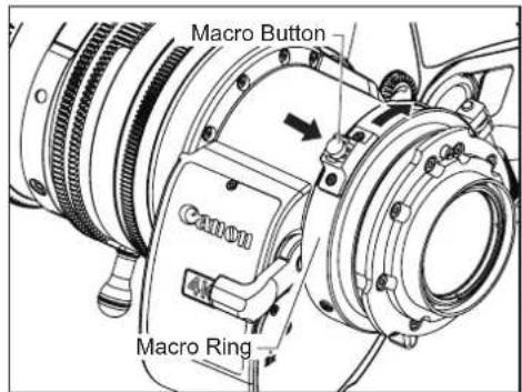
To operate the macro, press the macro button to unlock the macro ring. While holding it down, turn the macro ring at the rear of the lens clockwise as viewed from the camera side to allow macro shooting.
1 Set the lens to the widest angle by manual or servo zoom operation.
2 Bring the object into focus by turning the macro ring.
Macro operation is also possible at any zoom position other than the widest angle, but the object distance increases.
Multi-point Focus Shooting
In macro shooting, when zooming to change the focal length, the focal point varies.
The multi-point focus shooting technique uses this characteristic. The focal point is shifted by the zoom operation. Follow the steps bellow :
1 Zoom in to a far object, and bring it into focus by normal focus operation.
2 Zoom out to a near object and bring into focus by macro operation.
3 Zoom in to the far object again while not touching the macro button set by above step 2, and bring into focus again by normal focus operation.
5-6. SWITCH OPERATIONS
Functions can be assigned to the five switches: the VTR, RET, AUX switches, or AUX1 and AUX2 switches on the information display. "VTR", "RET", "Shtl", and "Fr1P" functions are assigned respectively by default.
The following steps explain how to assign the functions to the switches in basic mode. For further details, refer to the Information Display Operation Manual.
![MENU A Fr1P (A 1) Shtl [I-Tq]H IG:50 [Trk] OFF A2 Fr1P [Z.M.]](/content/2026/05/793037/images/ecda557001f1869379198a370b53a62c61c62dbbe7d9e96cc50d7b914905659a.jpg)
1 Press the DISPLAY switch to turn on the display.
2 After using the control key to select the name of the switch key to which the function is to be allocated, press the Set key. The name of the switch and the default or the previous setting now blink on the display.
3 Press the left or right key until the function to be changed to appears on the display.
4 Press the Set key. This completes the setting.
| Switch | Default value | Functions | ||||||||||
| Fr1P | Fr1F | Fr2 | P Fr2F | Sped | Shtl | NON | VTR | RET | ||||
| 1 V VTR | ● | ● | ● | ● | ● | ● | ● | |||||
| 2 R RET | ● | ● | ● | ● | ● | ● | ● | |||||
| 3 A Fr1P | ● | ● | ● | ● | ● | ● | ● | ● | ||||
| 4 A1 | Shtl | ● | ● | ● | ● | ● | ● | ● | ● | |||
| 5 A2 | Fr1P | ● | ● | ● | ● | ● | ● | ● | ● | |||
"●" indicates a combination of an assignable function and a switch.
(4) and (5) are AUX1 and AUX2 switches on the zoom demand.
| Switch name | Description |
| VTR | Starts/stops VTR operation. |
| RET | Hold down to view the main-line video on the view finder. |
| Fr1P, Fr2P | Press to move to the stored zoom/focus position.One position can be stored/called for Fr1P and Fr1F, and another for Fr2P and Fr2F. |
| Fr1F, Fr2F | |
| Sped | Press to move in the stored zoom direction (toward the telephoto end or the widest angle end) at the stored zoom speed. |
| Shtl | Press to move to the stored zoom position at the maximum speed. Release to return to the previous zoom position at the maximum speed. |
| NON | No function |
6 PRODUCT SPECIFICATIONS
| Model name | CJ12ex4.3B CJ20ex7.8B | |||
| Focal Length | 1.0x 4.3-52mm 7.8-156mm | |||
| 2.0x 8.6-104mm 15.6-312mm | ||||
| Zoom Ratio | 12 × 20 × | |||
| Maximum Relative Aperture | 1.0x | 1:1.8 (at 4.3-40.0mm)1:2.4 (at 52mm) | 1:1.8 (at 7.8-108mm)1:2.6 (at 156mm) | |
| 2.0x | 1:3.6 (at 8.6-80.0mm)1:4.8 (at 104mm) | 1:3.6 (at 15.6-216mm)1:5.2 (at 312mm) | ||
| Image Format Dia. 11mm | (9.6 x 5.4 mm) Dia. 11mm (9.6 x 5.4 mm) | |||
| Angular Field of View | Wide | 1.0x 96.3°×64.2° 63.2°×38.2° | ||
| 2.0x 58.3°×34.9° 34.2°×19.6° | ||||
| Tele | 1.0x 10.5°×5.9° 3.5°×2.0° | |||
| 2.0x 5.3° ×3.0° 1.8° ×1.0° | ||||
| Minimum Object distance (M.O.D)(Macro: 10mm from the lens vertex) | 0.3m | 0.8m | ||
| Object Dimensions at M.O.D | Wide | 1.0x | 76.4 × 43.0cm | 91.7 × 51.6cm |
| 2.0x | 38.2 × 21.5cm | 45.9 × 25.8cm | ||
| Tele | 1.0x 6.0 × 3.4cm | 4.8 × 2.7cm | ||
| 2.0x 3.0 × 1.7cm | 2.4 × 1.4cm | |||
| Flange back | 48mm (in air) | |||
| Thread for filters | 127mm P0.75(Hood Unit Thread Size) | 94mm P1.0 (Lens Barrel Thread Size)or 105mm P1.0 (Hood Unit Thread Size) | ||
| Zoom speed for full range | Max. 0.5s ± 0.2s | |||
| Focus speed for full range | 1.3s ± 0.3s | 1.5s ± 0.3s | ||
| Iris | Control from camera | |||
| Mount | B4 | |||
| Power source | DC12V (DC10 ~ 17V) | |||
| Current consumption | R type | Max 300mA | - | |
| A type | Max 500mA | |||
| Operating temperature | Temperature: -20°C ~ +45°CHumidity: 5% to 95%RH (no condensation) | |||
| Mass without hood | IRSE S | Approx. 2.10kg | - | |
| IASE S | Approx. 2.18kg | Approx. 2.18kg | ||
Memo
中文版
中文版为中华人民共和国用使用说明书。
| CJ12ex4.3B | IRSE S CJ20ex7.8B IASE S | |
| IASE S | ||
| IRSE-C S | ||
| IASE-C S |
① 光圈增益微调器
② 光圈瞬态自动开关
③ 光圈操作模式切换开关
④ 变焦翘板开关
⑤ RET开关(录像回放开关)
⑥ MEMO开关(内存开关)
⑦ AUX开关
⑧ 后焦锁定螺钉/后焦调节环
⑨ 定位销
⑩ 趋近拍摄按钮/微距光环
⑪ 扩展器切换杆
⑫ 光圈环
⑬ 变焦杆/变焦环
⑭ 聚焦环
⑮ 变焦·聚焦伺服/手动切换旋钮注)*仅限于IASE S, IASE-C S型镜头
⑯ 遮光罩锁定螺钉
① 显示屏开关
| 开关 默认值 | 可分配功能 | ||||||||||
| Fr1P | Fr1F | Fr2P | Fr2F | Sped | Sh | U1 | NON | VTR | RET | ||
| 1 V VTR | ● | ● | ● | ● | ● | ● | ● | ||||
| 2 R RET | ● | ● | ● | ● | ● | ● | ● | ||||
| 3 A | Fr1P | ● | ● | ● | ● | ● | ● | ● | |||
| 4 A1 | Sht1 | ● | ● | ● | ● | ● | ● | ● | |||
| 5 A2 | Fr1P | ● | ● | ● | ● | ● | ● | ● | |||
●表示可分配的功能与开关的组合。
| CJ12ex4.3B | IRSE S |
| IASE S | |
| IRSE-C S | |
| IASE-C S |
| CJ20ex7.8B | IASE S |
| CJ12ex4.3B | IRSE S CJ20ex7.8B IASE S | |
| IASE S | ||
| IRSE-C S | ||
| IASE-C S |
30-2, Shimomaruko 3-chome, Ohta-ku, Tokyo 146-8501, Japan
Canon Ru LLC
There are some differences in the external appearance of the drive unit for the IRSE S type and clutchless type.
Canada ____ Canon Canada, Inc.
Broadcast and Communications Div. 6390 Dixie Road, Mississauga, Ontario, L5T 1P7, Canada
Tel:+1(905)795-2012 Fax:+1(905)795-2087
Mexico ____ Canon Mexicana, S. de R.L. de C.V.
Call Center Div. Blvd. Manuel Avila Camacho No,138,
Col. Lomas de Chapultepec, Mexico, D.F. Tel:+52 55 5249 4905
North & South America ____ Canon U.S.A., Inc.
ITCG METC 65 Challenger Road, Ridgefield Park, NJ, 07660 Tel:+1(800) 423-5367 (Toll Free) Fax:+1(201) 807-3344
ASIA
Asia & Hong Kong, S.A.R. ____ Canon Hongkong Company Ltd.
ICP Marketing Div. 19/F, The Metropolis Tower, 10 Metropolis Drive, Hunghom, Kowloon, Hong Kong
Tel:+852-3191-2333
South & Southeast Asia ____ Canon Singapore Pte. Ltd.
REG ICP Sales & Marketing Div. 1 Fusionopolis Place, #15-10, Galaxis, Singapore 138522
Tel:+65-6799-8888
Broadcast Products Div. 3 The Square, Stockley Park, Uxbridge, Middlesex, UB11 1ET UK
Tel:+44(0)20-8588-8140 Fax:+44(0)20-8588-8929
Canon Europa N.V. Bovenkerkerweg 59, 1185 XB Amstelveen, The Netherlands
OCEANIA
Oceania ____ Canon Australia Pty. Ltd.
CCI Division Building A, The Park Estate, 5 Talavera Road, Macquarie Park, NSW 2113, Australia Tel:+61(0)2-9805-2000
Canon
キャノン株式会社
30-2, Shimomaruko 3-chome, Ohta-ku, Tokyo, 146-8501, Japan
Subject to change without notice.
进口商:佳能(中国)有限公司
Pub No. B-IM-20243-3
© 2016.08 CANON INC.
原产地:日本
- FCC REGULATIONS
- Canadian Radio Interference Regulations
- CE
- - FOREWORD -
- STANDARD PRODUCT LIST
- GENERAL SAFETY INFORMATION
- HANDLING THE PRODUCT
- WARNING
- CAUTION
- NOTE
- DEALING WITH ABNORMALITIES
- MAINTENANCE AND INSPECTION
- STORAGE
- TO THE CUSTOMER
- CANON INC.
- NOMENCLATURE
- HOW TO MOUNT
- 2-1. MOUNT THE LENS ON THE CAMERA
- 2-2. MOUNT THE HOOD ON THE LENS
- 2-3. TURN IT ON
- ADJUSTMENT
- 3-1. BACK FOCUS ADJUSTMENT
- 3-2. IRIS GAIN ADJUSTMENT
- MODE SETTING
- 4-2. SETTING ITEMS IN BASIC MODE
- 4-3. SETTING ITEMS IN FULL MODE
- 4-4. SETTING ITEMS IN ANALOG MODE
- OPERATION
- 5-1. ZOOM OPERATION
- 5-1-1. Manual Zoom Operation
- 5-1-2. Servo Zoom Operation
- 5-1-3. Maximum Zoom Speed Adjustment
- 5-1-4. Zoom Track Function (only for servo zoom)
- Setting the Zoom Track Positions
- 5-1-5. Shuttle-Shot Function
- 5-1-6. Speed Preset
- How to operate the speed preset function
- How to cancel movement in Speed Preset
- 5-1-7. Framing Preset
- Framing Preset [Zoom]/[Focus]/[Z+F] Setting
- Setting the framing memory position
- Moving to the framing memory position
- Canceling the movement to the framing memory position or switching to other zoom operation
- [Zoom Framing Preset]
- [Focus Framing Preset]
- [Zoom, Focus Framing Preset]
- 5-1-8 Clutchless Zoom ('-C S"LENS only)
- 5-2-2. Servo Focus Operation
- 5-4. IRIS OPERATION
- 5-4-1. Automatic Iris Operation
- 5-4-2. Manual Iris Operation
- Multi-point Focus Shooting
- 5-6. SWITCH OPERATIONS
- PRODUCT SPECIFICATIONS
- 中文版
- ASIA
- OCEANIA
- Canon
Brand : CANON
Model : CJ12ex4.3B Series
Category : Lens