CT-6000 - Exercise bike Joy Sport - Free user manual and instructions
Find the device manual for free CT-6000 Joy Sport in PDF.


| Product Type | Exercise bike (stationary) |
| Brand | Joy Sport |
| Model | CT-6000 |
| Dimensions (approx.) | 100 cm (L) x 50 cm (W) x 120 cm (H) |
| Weight (approx.) | 35 kg |
| Power Supply | 2 x AA batteries (for computer) |
| Computer Display | LCD screen showing Time, Speed, Distance, Calorie, Pulse, Body Fat, BMI, BMR |
| Functions | Scan, Count up/down, Pulse Recovery, Body Fat Measurement, Target Heart Rate |
| Resistance System | Manual adjustment knob |
| Heart Rate Monitoring | Hand pulse sensors (optional chest belt) |
| Pedals | Adjustable with toe straps |
| Transport Wheels | Yes, 2 on front stabilizer |
| Frame Material | Steel |
| Maintenance | Clean with mild soap and water; periodically retighten bolts |
| Safety Precautions | Keep children/pets away; assemble on flat floor; do not use abrasive cleaners |
| Spare Parts Availability | Refer to parts list; contact Joy Sport for replacements |
| Warranty | 12 months on manufacturing defects |
Frequently Asked Questions - CT-6000 Joy Sport
User questions about CT-6000 Joy Sport
0 question about this device. Answer the ones you know or ask your own.
Ask a new question about this device
Download the instructions for your Exercise bike in PDF format for free! Find your manual CT-6000 - Joy Sport and take your electronic device back in hand. On this page are published all the documents necessary for the use of your device. CT-6000 by Joy Sport.
USER MANUAL CT-6000 Joy Sport
natural_image
Line drawing of a stationary exercise machine with levers and wheels (no text or symbols)5813 AP Ysselsteyn (LB)
info@joysport.nl
www.joysport.nl
Geachte klant,
5813 AP Ysselsteyn (LB)
info@joysport.nl
www.joysport.nl
OVERZI CHT VAN DE CT-6000

1. VERPAKKI NG RECYCLI NG:
Borgmoer, 4 Stuks; (26) M10*40 Bout, 4 Stuks; (29) M*45 Inbus bout, 4 Stuks;
Multifunctionele sleutel, 1 Stuk; Inbus sleutel, 1 Stuk.
ONDERDELEN OVERZICHT.

- MONTAGE.
Dan is dit 220 minus 40 is 180 MAXIMALE HARTSLAG.
180 X 60% is 108 en 180 X 70% is 126.
natural_image
Line drawing of a stationary exercise machine with levers and wheels (no text or symbols)5813 AP Ysselsteyn (LB)
info@joysport.nl
www.joysport.nl
Geehrter Kunde
5813 AP Ysselsteyn (LB)
info@joysport.nl
www.joysport.nl
Übersicht CT-6000

ZUSAMMENBAU
Teilliste:
| Nr. | Name und S | pezifikation | Men | ge | Nr. Name | und S | pezifikation | Men | ge |
| 1 | Hauptrahmen | 1 | ppe | crack | 2 | 49 | |||
| 2 | Hinterer Stabilisator 1 50 Linke Abdeckka | ppe | 1 | ||||||
| 3 | Front Stabilisator 1 | 51 | Crank | (L/R) | 2 | ||||
| 4 | Anzeigepfosten | 1 | 52 | ppe | Rechte Ac | ||||
| 5 | Pedalarm(L/R) | 2 | 53 | Lager R12 | 2 | ||||
| 6 | Unterer Schwankar(HR) | 2 | 54 | Crank Welle | 1 | ||||
| 7 | Oberer Schwankar(HR) | 2 | 55 | Feder | |||||
| 8 | Handgriff | 1 56 | Riemen | Antrieb | 1 | ||||
| 9 | Komputer | 1 57 | Justierun | g Rad montage | 1 | ||||
| 10 | Fusspedall (L/R) | 2 | 58 | Justierrolle (Riemen) | 1 | ||||
| 11 | M10 Bogenring | 4 | 59 | Buchse Justierrolle | 1 | ||||
| 12 | Pedalarm Halter | 2 | 60 | M10* 6.35T Mutter | 1 | ||||
| 13 | M8* 70 Inbus Bolzen | 2 61 $ | pannfeder | 1 | |||||
| 14 | Schwankarm Kappe | 2 | 62 | Ring | 1 | ||||
| 15 | Schwankarm Kappe | 2 | 63 | Ring | 1 | ||||
| 16 | M10* 92 Bolzen | 4 | 64 | Feder | 2 | ||||
| 17 | M8 Bogenring | 10 | 65 Ma | gnet | 1 | ||||
| 18 | M10 Mutter | 7 | 66 Ma | gnet Feder | 1 | ||||
| 19 | M8* 20 Inbus Bolzen | 7 | 67 | M5* 30 Bolzen | 1 | ||||
| 20 | M4* 20 Parker | 7 | 68 | M5 Mutter | 2 | ||||
| 21 | M4* 10 Bolzen | 8 | 69 | M8* 20 Inbus Bolzen | 1 | ||||
| 22 | Ring | 2 | 70 | ||||||
| 23 | M8 Federring | 10 | 71 | Handgriff Impulsaufnehmer | 2 | ||||
| 24 | Ring | 2 | 72 | Handgriffstab Schaumgummi | 2 | ||||
| 25 | Buchse | 2 | 73 | Handgriffstab-Endstöpsel | 2 | ||||
| 26 | M10* 40 Bolzen | 4 | 74 | Unterer Schwankarm Welle | 2 | ||||
| 27 | M6* 20 Bolzen | 2 | 75 Pedalkno pf | 4 | |||||
| 28 | M6* 12 Bolzen | 2 | 76 Widerstandkno pf | 1 | |||||
| 29 | M8* 45 Inbus Bolzen | 4 77 | Handgriffstab Schaumgummi | 1 | |||||
| 30 | M5* 12 Bolzen (Am Komputer) | 4 78 | M10* 48 Inbus Bolzen | 2 | |||||
| 31 | M10 Ring | 6 | 79 | Transporträder | 2 | ||||
| 32 | M8 Mutter | 10 | 80 | 6001 Lager | 2 | ||||
| 33 | Riemen | 1 81 | Ring | 4 | |||||
| 34 | Stabilisator Kappe | 4 | g 82 | Rin | 2 | ||||
| 35 | Stellbolzen | 2 83 | Ring | 6 | |||||
| 36 | M8* 52 Inbus Bolzen | 2 84 | Ring | 2 | |||||
| 37 | Fusspedal Kappe | 2 | g 85 | Rin | 2 | ||||
| 38 | Fusspedal Kappe | 2 | 86 | M4* 20 Bolze | |||||
| 39 | Schwungrad Achse | 1 87 | M6 Federrin | g | 4 | ||||
| 40 | Schwungrad | 1 | 88 | M6* | |||||
| 41 | Untere Schwankarm Buchse | 4 | 89 | Unterer Winderstandkabel | 1 | ||||
| 42 | M8* 25 Inbus Buchse | 2 | 90 | Unterer Sensorkabel | 1 | ||||
| 43 | M6 Ring | 4 | 91 | Oberer Schwankarm Welle | 4 | ||||
| 44 | M6 Mutter | 4 | 92 | Pedalarm Halter Buchse | 4 | ||||
| 45 | Abdeckkappe rechts vorne | 1 93 | M4* 16 Bolzen | 2 | |||||
| 46 | Abdeckkappe links vorne | 1 | 94 | Oberer Sensorkabel | 1 | ||||
| 47 | 5/16-18* 25 Bolzen | 4 95 | M5* 45 Bolzen | 1 | |||||
| 48 | M6* 16 Bolzen | 4 96 | M5 Bo | genring | 1 | ||||
odeckka
18 Bol:

ENTER:
natural_image
Line drawing of a stationary exercise machine with visible components and wheels (no text or symbols)PLEASE READ THIS MANUAL BROCHURE BEFORE ASSEMBLING THE PRODUCT. KEEP THIS INSTRUCTION AS FUTURE REFERENCE.
Joy Sport Importer
Fitness-Import
Timmermannsweg 46
5813 AP Ysselsteyn (LB)
info@joysport.nl
www.joysport.nl
Dear customer,
We want to thank you for having chosen a JOY SPORT product, and wish you a lot of fun and success during training with your JOY SPORT exercisers.
Please note and follow the enclosed safety and assembly instructions carefully.
If you have questions please do not hesitate to contact us.
Guarantee,
This guarantee covers all manufacturing and material flaws on JOY SPORT products purchased from an authorized JOY SPORT dealer for a period of 12 months from purchase.
If you wish to make a claim under the guarantee, JOY SPORT shall be entitled to repair or replace the defective unit or part at its discretion.
The owner of the unit must pay for the transport costs and any dealer's workshop costs.
To make a claim under the guarantee, take your guarantee card to your dealer.
The dealer will then take the necessary action.
If this is not possible, contact your national JOY SPORT importer.
The following are not covered by the guarantee : normal wear and tear and the consequences of improper treatment or damage caused by the purchaser or third persons and faults which are due to other circumstances.
Claims may not be made under the guarantee if modifications have been made to the original construction or equipment or if JOY SPORT original parts were not used to repair the unit.
In no event the manufacturer shall be liable for incidental or consequential losses, damages or expenses in connection with exercise products.
Fitness-Import
Timmermannsweg 46
5813 AP Ysselsteyn (LB)
info@joysport.nl
www.joysport.nl
GENERAL OUTLOOK

1. PACKAGE RECYCLING:
Please take care to recycle the parts which can be.

Also dispose of the used parts properly.
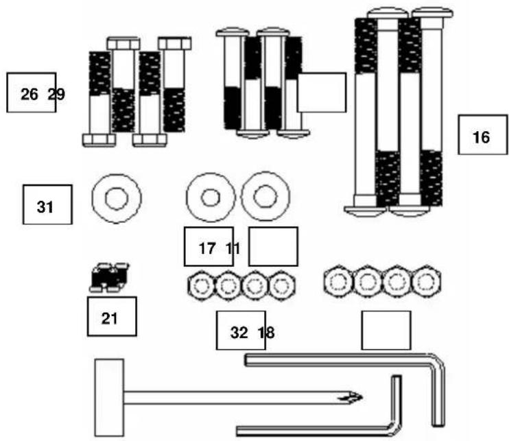
You will see the hardware illustration below indicating the assembling tools. Taking sometime to identify them could be helpful in the process of assembly. All of them will be packed in a PE bag.
(Please refer to the picture below): (16) M10*92 carriage screw ,4pcs ; (11) M10 arc
washer,4pcs;(17)M8 arc wahser, 4pcs;(18)M10 nylon cap,4pcs ; (21) M4*10 round screw,
4pcs;(31) M10 flat wahser, 4pcs; (32) M8 nylon cap, 4pcs; (26) M10*40 outer hexagon screw, 4pcs; (29) M*45 inner hexagon screw, 4pcs; T shape spanner, 1pcs; L shape spanner,1pcs.

GENERAL REVIEW ON THE MAIN PARTS ASSEMBLY.

- ASSEMBLY.
You will receive the item with inner system assembled in advance. What you have to do is just to assemble the external components. A PE bag with assembling tools is available with each carton. Unseal the bag and take the tools out. A flat and even floor is required for the main frame laying. Make sure there is no other object sharp within 1.5m of main frame fron all direction.
2.- Rear stabilizer.
- Insert the M10*92 carriage screw (16) through the rear stabilizer (2) and the bottom bracket of the main frame (1), then use M10 nylon cap (18) and M10 arc washer (11) to lock them up.

3.- Front stabilizer.
- Insert the M10*92 carriage screw (16) the front stabilizer (3) and the bottom bracket of the main frame (1), then use M10 nylon cap (18) and M10 arc washer (11) to lock them firm.

4.- Pedals
- Put the right pedal (10R) on the pedal tube (5R) and insert M10*40 outer hexagon screw (26) through the pedal and pedal tube. Use the M10 flat washer (31) and pedal adjustor (75) to lock them firm.
- Put the left pedal (10L) on the pedal tube (5L) and insert M10*40 outer hexagon screw (26) through the pedal and pedal tube. Use the M10 flat washer (31) and pedal adjustor (75) to lock them firm.

5. - Meter post
- Please make the TCD stay at the lowest level which enables the TCD wire to be longest. It will help when you try to hook the TCD upper segment with the TCD lower segment.
- Remove the tow M8*70 inner hexagon screws (13), two M8 nylon caps (32), six M8 spring washers (23), six M8 arc washers (17) and four M8*20 inner hexagon screws (19).
- Take the meter post (4) close to the lower meter post. Connect the TCD upper segment (76) with the TCD lower segment (89); connect the upper sensor wire (94) with the lower sensor wire (90).
- Finally fix the meter post onto the lower meter post and use the removed screws and washers to lock them up.

6. - Lower swing arm and pedal tubes.
- First please use the L shape spanner to remove the two M6*20 screws (φ9.9*51) (27), two M6*12 hexagon screws (28) and two lower swing arm axles (74) which are pre-assembled between the U bracket at end of the pedal tubes (5L/5R).
- Put the lower swing arm axle (74) into the hole of the left lower swing arm (6).
- Fix the assembled lower swing arm (6L) between the U brackets at end of the pedal tubes. Use the removed the two M6*20 screws (φ9.9*51) (27), two M6*12 hexagon screws (28) and two lower swing arm axles (74) to fix the left-side lower swing arm. And finally use the L shape spanner to screw them tight.
- Use M4*10 round screw (21) to lock the pedal tube cover 1 (37) and pedal tube cover (38).

NOTE: THE CONNECTING WAY OF THE RIGHT SIDE SWING ARM IS SAME AS THE LEFT SIDE.
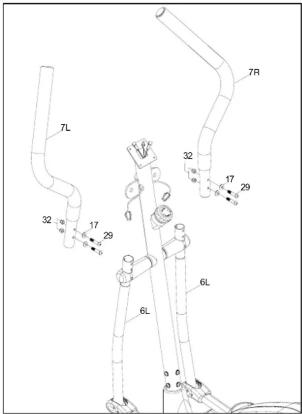
7. - Upper swing arm and lower swing arm.
- Put the left upper swing arm (7L) into the lower swing arm (6L). And use M8*45 inner hexagon screw (29) to insert the M8 arc washer (17), upper swing arm, lower swing arm and the M8 nylon cap. Screw them tight.
- NOTE: THE ASSEMBLING WAY OF THE RIGHT UPPER SWING ARM (7R) IS SAME AS THE LEFT ARM.
8. -Hand bar and meter.
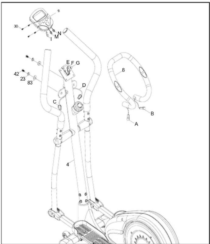
- Remove the two M8*25 inner hexagon screws (42), two M8 spring washers (23) and two OD20*ID8.5*2.0T flat washers (83) which are pre-assembled on the hand bar (8).
- Take the hand bar (8) close to the top of the meter post. Connect the hand pulse wire port C on the meter post with the hand pulse wire port A on the hand bar; connect the wire port D on the meter post with the wire port B on the hand bar.
- Attach the hand bar (8) onto the top of the meter post. Use the removed screws and washers to lock them up.
- Then remove the four M5*12 screws (30) on back of the meter (9). Put two AA size batteries into the slot and cover them.
- Take the meter close to the top of the meter post. Connect the wire port F with wire port I; connect the wire port E with wire port M; connect the wire port G with wire port N. Please refer to the photo.
- Finally attach the meter on the meter post and use the removed screws, spring washers and washers to lock them up.
Maintenance and note:
Due to the high quality of the paint and upholstery used in this unit, the frames and upholstery need only be kept free from grime and dust by occasionally washing with mild soap and water. Never use any abrasive cleaners or strong detergents.
Do not tighten bolts, screws and locknuts until all are in place, except where noted. Periodically go back and retighten all bolts, screws and locknuts.
Exercise equipment contains many moving parts which could cause injury to children and / or pets. Take proper precautions when equipment is not in use.
Be sure to read and follow the instructions carefully while assembling this unit. Use the hardware illustrations to identify the different types of bolts, screws, washers and locknuts.
EXPLODED DIAGRAM

Parts List
| Nr. | Name &pecification | Qty. | Nr. Name & S | pecification | Qty. |
| 1 | main frame 1 | 49 | crank | cover 2 | |
| 2 | rear stabilizer 1 50 left bob | y cover 1 | |||
| 3 | front stabilizer 1 51 crank cross bar | (L/R) | 2 | ||
| 4 | meter post | 1 52 | ri | ght body bar | 1 |
| 5 | pedal tute (L/R) | 2 | 53 | bearing R12 | 2 |
| 6 | lower sqArm(L/R) | 2 | 54 | crank alxe | 1 |
| 7 | upper swing arm(L/R) | 2 | 55 φ19 button for | 1 | |
| 8 | hand bar | 1 | 56 plabet | 1 | |
| 9 | meter | 1 | 57 | just wheel fixer | 1 |
| 10 | pedal (L/R) | 2 | 58 | adjust wheel | 1 |
| 11 | M10 arc washer | 4 59 | ad | just wheel gap | 1 |
| 12 | pedal tube adjustor | 2 | 60 ylon cap M10*6.35T | 1 | |
| 13 | M8*70 inner hexagon screw | 2 61 | ad | just wheel spring | 1 |
| 14 | swing arm cover 1 | 2 62 | gap washer | 1 | |
| 15 | swing arm cover 2 | 2 63 | curve washer | 1 | |
| 16 | M10*92 carriage screw | 4 64 | C sha | pe button withφ12 | 2 |
| 17 | M8 arc washer | 10 | 65 ma | gnet | 1 |
| 18 | M10 nylon cap 7 66 ma | qnet spring | 1 | ||
| 19 | M8*20 inner hexagon screw | 7 67 | M5*30 | screw 1 | |
| 20 | M4*20 cross screw | 7 68 | M5 nut | 2 | |
| 21 | M4*10 round screw | 8 69 | M8*20 | inner hexa gon screw | 1 |
| 22 | OD31.8*ID8.5*3.0T flat washer | 2 70 | swin | q arm gap | 2 |
| 23 | M8 spring washer | 10 | 71 hand pulse | 2 | |
| 24 | OD25.4*ID8.5*3.0T flat washer | 2 | 72 | handle bar foam | 2 |
| 25 | tube washer | 2 | 73 | handle bar inner cap | 2 |
| 26 | M10*40 outer hexagon screw 4 | 74 | lower swin g arm alxe | 2 | |
| 27 | M6*20 screw (φ9.9*51) | 2 | 75 | pedal adjustor | 4 |
| 28 | M6*12 hexgaon screw | 2 | 76 | TCD upper segment | 1 |
| 29 | M8*45 inner hexagon screw | 4 77 | handle bar foma | 1 | |
| 30 | M5*12 screw (on meter) | 4 | 78 M10*48 inner hexa gon screw | 2 | |
| 31 | M10 flat washer | 6 | 79 trans portation wheel | 2 | |
| 32 | M8 nylon cap | 10 | 80 | 6001 bearing | 2 |
| 33 | belt | 1 | 81 | OD32*ID19.5*0.T flat washer | 4 |
| 34 | stabilizer caps | 4 | 82 | OD23*ID19.5*0.5T wave | 2 |
| 35 | rear stabilizer adjustor | 2 | 83 | OD20*ID8.5*2.0T flat washer | 6 |
| 36 | M8*52 inner hexagon screw | 2 | 84 | OD21.7*ID16*0.3T wave | 2 |
| 37 | pedal tube cover 1 | 2 | 85 | OD25.4*ID16.5*2.0T flat | 2 |
| 38 | pedal tube cover 2 | 2 | 86 | M4*20 flat screw | 10 |
| 39 | flywheel axle | 1 | 87 M6 s pring washer | 4 | |
| 40 | flywheel | 1 | 88 M6*18 outer hexa gon screw | 4 | |
| 41 | lower swing arm cushion | 4 | 89 | TCD down segment | 1 |
| 42 | M8*25 inner hexagon screw | 2 | 90 lower sensor wire | 1 | |
| 43 | M6 washer | 4 | 91 | swirarm axle cushion | 4 |
| 44 | M6 nylon cap | 4 | 92 | pedal tube alxe cushion | 4 |
| 45 | right front cover | 1 | 93 | M4*16 screw on hand pulse | 2 |
| 46 | left front cover | 1 | 94 u | pper sensor wire | 1 |
| 47 | 5/16-18*25 screw | 2 | 95 | M5*45 screw on TCD | 1 |
| 48 | M6*16 screw | 8 | 96 | M5 arc washer on TCD | 1 |

COMPUTER MANUAL.
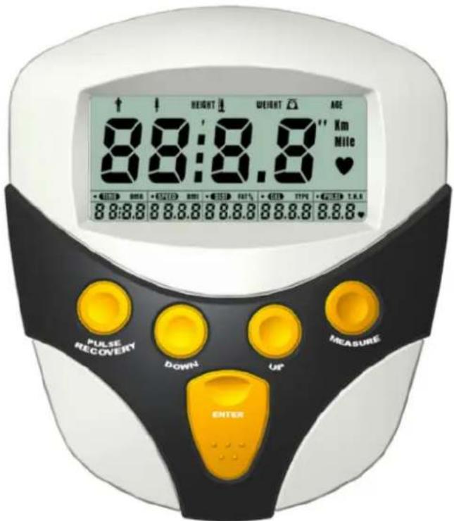
KEY GUIDE
ENTER : 1. Select function to be preset. Gender-Height-Weight-Age-Time-Distance-Calorie-Pulse
2 Press this button to enter setting mode.
3 Press this button to confirm the setting values.
4 Hold two seconds to reset all of the values to zero.
5 Hold over 5 seconds, the display and function will return to preset your personal data for body fat measuring.
PULSE RECOVERY: Press this button going into pulse recovery detecting. MEASURE: Press this button going to measure your body fat detecting. Before operating this function, you have to enter your personal data in monitor.
UP : 1. Increase the setting value of the following functions.
Gender -Height-Weight-Age-Time-Distance-Calorie-Pulse
- Select function and display on the main screen during exercise.
Scan-Time-Speed-Distance -Calorie -Pulse.
DOWN : 1. Decrease the setting value of the following functions.
Gender -Height-Weight-Age-Time-Distance-Calorie-Pulse
- Select function and display on the main screen during exercise.
Scan -Pulse-Calorie-Distance-Speed-Time.
BATTERY REPLACEMENT
1 Please install 2 pieces of AA or UM-3 batteries in the battery case on the back of monitor.
2 Ensure that the batteries are correctly fitted. Battery must be correctly positioned and make sure the battery spring is properly contacted with battery.
3 If the display appears blank or display only partial segment, remove the batteries and wait 15 seconds, then replace.
4 Whenever remove batteries, all the functions values will be reset to zero.
5 The batteries must be removed from the appliance before it is scrapped and that they are disposed of safely.
FUNCTIONS AND OPERATIONS i
AUTO ON/OF
The monitor will wake up automatically if the exercise machine is in motion. If stop exercising for over 4 minutes, monitor will turn off and reset all function values to zero.
SCAN
Press the button of UP or DOWN until the dot of scanning flash on the screen. Monitor will display the following function and each function will keep 5 seconds on the main screen. Time Speed-Distance Calorie Pulse.
TIME
Press the button of UP or DOWN until the dot of TIME display on the screen. Monitor will display the Time function on the main screen. If you want to setup the value, please press the button of ENTER to TIME function and press the UP or DOWN button to enter the value you want.
Count up:
Without setting the time value, the monitor will count up the time from 00:00\~99:59.
Count down:
Setting the exercise time from 1:00\~99:00 minutes, the monitor will count down from your setting values. Once reach setting value, monitor will alarm.
SPEED
Press the button of UP or DOWN until the dot of SPEED display on the screen. Monitor will display the current speed on the main screen. The monitor will display the current speed from 0.00 \~ 999.9 Km or Mile.
DISTANCE
Press the button of UP or DOWN until the dot of DIST display on the screen. Monitor will accumulate the distance trip. If you want to setup the value, please press the button of ENTER to DIST and press the UP or DOWN button to enter the value you want.Count up: Without setting the distance value, the monitor will count up the distance from 0.1\~999.9Km or Mile. Count down:
Setting the exercise distance from 1.0\~999.0 Km or Mile, the monitor will count down from your setting values. Once reach setting value, monitor will alarm.
CALORIE
Press the button of UP or DOWN until the dot of CAL display on the screen. Monitor will accumulate the calorie consumption. If you want to setup the value, please press the button of ENTER to CAL and press the UP or DOWN button to enter the value you want. Count up: Without setting the distance value, the monitor will count up the distance from 0.1\~9999. Count down: Setting the exercise calorie from 1.0\~9999, the monitor will count down from your setting values. Once reach setting value, monitor will alarm.
PULSE (Target Heart Rate)
Press the button of UP or DOWN until the dot of pulse display on the screen. The monitor will display your current heart rate in beats per minute. If you want to setup the value, please press the button of ENTER to T.H.R. and press the UP or DOWN button to enter the value you want. Pulse Limit: Setting the value of pulse limit between 60 to 220, the monitor will measure your heartbeats. Once reach setting value, monitor will flash until your heartbeats under your setting value. If the sensor is contact with hand, before measuring your pulse, place the palms of your hands on the both of the contact pads and the monitor will show up your current heart beat rate in beats per minute (BPM) on the LCD display. If the sensor is contact with ear, before measuring your pulse rate, clip the sensor to earlobe after rubbing earlobe for several times to ensure maximum circulation. And clip cord to collar to reduce excessive sensor vibration.
(Options: Chest Belt for wireless pulse system is optional. If wireless pulse system is adapted, please refer to the leaflet of wireless pulse system. It may not apply to all the models, only if the option is along with the computer.)
NOTE:
- If no pulse signal input within 16 seconds, the display will indicate It is a power savin device. Customer can press the up & down keys to restart Pulse function.
PULSE RECOVERY
It is a function to check the condition of pulse recovery when stop exercising that is scaled from F1.0 to F6.0 while F1.0 means the best and F6.0 means the worst and the increment is 0.1. This function may reflect your heart pulse recovery ability and improve it through exercise. In order to get rated correctly, users must test it right after the workout finished by pressing “ RECOVER ” i± key and then st op exercisi ng. After t he key is pressed, please al s apply the heart rate detector appropriately. The test will last for 1 minute and the result will show in the display. When press again will out of PULSE RECOVERY mode.
BODY FAT MEASUREMENT (Body Mass Index)
When you turn on the monitor or press the ENTER button over 6 seconds, the monitor will go into BODY FAT MEASUREMENT function. Before press MEASURE button to measure your body fat, you have to enter your personal data into monitor. Select the personal data and press UP or Down button to enter your personal data. Then press MEASURE button and place the palms of your hands on the both of contact pads. The monitor will show your body fat ratio on LCD. The default value of personal data is as described as following. The personal data will be not kept in monitor when monitor power off or be reset. GENDER: male, HEIGHT: 175 cm, WEIGHT: 70 kg, AGE: 30 years old.
A. Body Types: There are 9 body types divided according to the FAT% calculated. Type 1 is Ultra-sportsman type. Type 2 is Ideal-sportsman type. Type 3 is Ultra Slim type. Type 4 is Sportsman type. Type 5 is Ideal-healthy Type. Type 6 is Slim type. Type 7 is Too fat. Type 8 is Fat type. Type 9 is Ultra body fat type.
B. BMR: Basal Metabolism Ratio. The monitor will calculate the data of gender, height, weight and age to show your value. The value will show on the screen from 1 \~ 9999 Kcal.
C. BMI: Body Mass Index. The monitor will calculate the data of height and weight to show your value. The value will show on the screen from 1.0 \~ 99.9 on screen.
D. FAT % (BODY FAT RATIO): The monitor will calculate the data of gender, height, weight and age to show your BODY FAT RATIO. The value will show on screen from 5 \~ 50%.
- Geachte klant,
- VERPAKKI NG RECYCLI NG:
- - MONTAGE.
- Geehrter Kunde
- Übersicht CT-6000
- ZUSAMMENBAU
- ENTER:
- Joy Sport Importer
- Dear customer,
- Guarantee,
- PACKAGE RECYCLING:
- - ASSEMBLY.
- 2.- Rear stabilizer.
- 3.- Front stabilizer.
- 4.- Pedals
- - Meter post
- - Lower swing arm and pedal tubes.
- - Upper swing arm and lower swing arm.
- -Hand bar and meter.
- Maintenance and note:
- EXPLODED DIAGRAM
- KEY GUIDE
- BATTERY REPLACEMENT
- FUNCTIONS AND OPERATIONS i
- AUTO ON/OF
- SCAN
- TIME
- SPEED
- DISTANCE
- CALORIE
- PULSE (Target Heart Rate)
- NOTE:
- PULSE RECOVERY
- BODY FAT MEASUREMENT (Body Mass Index)
Brand : Joy Sport
Model : CT-6000
Category : Exercise bike