HT-Golf - Exercise bike Joy Sport - Free user manual and instructions
Find the device manual for free HT-Golf Joy Sport in PDF.


| Product Type | Exercise Bike |
| Brand | Joy Sport |
| Model | HT-Golf |
| Dimensions | 100 x 50 x 130 cm |
| Weight | 25 kg |
| Maximum User Weight | 120 kg |
| Resistance System | Magnetic |
| Resistance Levels | 8 |
| Display | LCD with time, speed, distance, calories, pulse |
| Power Source | 2 AA batteries (not included) |
| Pedals | Adjustable with straps |
| Seat | Adjustable vertically and horizontally |
| Handlebar | Adjustable with pulse sensors |
| Transport Wheels | Yes |
| Foldable | No |
| Maintenance | Clean with damp cloth; lubricate moving parts monthly |
| Safety Features | Stabilizers, emergency brake |
| Spare Parts | Available from manufacturer |
| Warranty | 2 years |
| Intended Use | Home use |
Frequently Asked Questions - HT-Golf Joy Sport
User questions about HT-Golf Joy Sport
0 question about this device. Answer the ones you know or ask your own.
Ask a new question about this device
Download the instructions for your Exercise bike in PDF format for free! Find your manual HT-Golf - Joy Sport and take your electronic device back in hand. On this page are published all the documents necessary for the use of your device. HT-Golf by Joy Sport.
USER MANUAL HT-Golf Joy Sport
natural_image
Line drawing of a stationary exercise bike with adjustable arms and legs (no text or symbols)Joy Sport Importeur
Fitness-Import
Timmermannsweg 46
5813 AP Ysselsteyn (LB)
info@joysport.nl
www.joysport.nl
Geachte klant,
5813 AP Ysselsteyn (LB)
info@joysport.nl
www.joysport.nl
1. Montage:
natural_image
Close-up of a black plastic clamp holding a small mechanical component, with a red arrow indicating rotation (no text or symbols visible)tek3-A

natural_image
Close-up of a hand holding a black plastic object with a red arrow pointing to a feature (no text or symbols visible)tek3-B


natural_image
Close-up of a black plastic device with a red arrow indicating rotation or adjustment (no visible text or symbols)tek3-C

natural_image
Technical line drawing of two mechanical components with no visible text or symbols5. Zadel (zie tek 4)
natural_image
Close-up of a mechanical component with a red arrow and label 'NtM' pointing to a bolted joint (no readable text or symbols beyond the label)tek4-A


tek4-B
natural_image
Line drawing of a stationary exercise bike with adjustable arms and legs (no text or symbols)Onderdeeltekening:

Onderdelen lijst:
natural_image
Line drawing of a stationary exercise bike with adjustable arms and legs (no text or symbols)Joy Sport Importer
Fitness-Import
Timmermannsweg 46
5813 AP Ysselsteyn (LB)
info@joysport.nl
www.joysport.nl
Dear customer,
We want to thank you for having chosen a JOY SPORT product, and wish you a lot of fun and success during training with your JOY SPORT exercisers.
Please note and follow the enclosed safety and assembly instructions carefully.
If you have questions please do not hesitate to contact us.
Guarantee,
This guarantee covers all manufacturing and material flaws on JOY SPORT products purchased from an authorized JOY SPORT dealer for a period of 24 months from purchase.
If you wish to make a claim under the guarantee, JOY SPORT shall be entitled to repair or replace the defective unit or part at its discretion.
The owner of the unit must pay for the transport costs and any dealer's workshop costs.
To make a claim under the guarantee, take your facture to your dealer.
The dealer will then take the necessary action.
If this is not possible, contact your national JOY SPORT importer.
The following are not covered by the guarantee : normal wear and tear and the consequences of improper treatment or damage caused by the purchaser or third persons and faults which are due to other circumstances.
Claims may not be made under the guarantee if modifications have been made to the original construction or equipment or if JOY SPORT original parts were not used to repair the unit.
In no event the manufacturer shall be liable for incidental or
consequential losses, damages or expenses in connection with exercise products.
Fitness-Import
Timmermannsweg 46
5813 AP Ysselsteyn (LB)
info@joysport.nl
www.joysport.nl
Before using, please read all the cautions and instructions of product as well as keep this User Manual for future reference.
Safety instruction to avoid any accident, we ask for your attention:
- This equipment is only for indoor using but not medical treatment.
- This HC class equipment's tension is controlled by electronic motor, so it is not allowed to use without the control by system
- Apart from the place of high temperature, wet and water.
- There is TCD on the computer post. Computer will be stop automatically if you stop use pedal.
- Please read the user manual carfully before using.
- Please put this equipment always on a flat and fixed place.
- Don't seat in the saddle and other parts of product.
- Pay your attention to leave enough room and distance (at least 1.5m) to every direction on your machine.
- Faulty or non-normal exercise would be a scathe to your body.
- To ensure the safety situation, please regularly check the damage and fret, and repair right after finding some parts are out of order. Please don't start to use before assembly finished.
- Screw and nut need regularly check.
- This exercise equipment can not be used as toy or game machine.
- Owner has the responsibility to tell other users about the attention.
- This equipment is use for inner instead of outer.
- Please put a mat under the equipment to protect the ground.
- Please don't transfer this equipment alone.
- Please use the equipmnet according to product instruction.
- Please don't close your eyes when using this equipment.
- Child is not allowed to come near this equipment without the watching of adults.
Notes:
Before using, please consult with your doctor. This is very important, especial for the year beyond 35 or the person who had ever healthy problems.
Packing:
We select the environment protected and reproducible material:
— Outer carton is paper material
— Inner packing are paper material and plastic foam.
— Plastic film and packing bag is PE.
Sealed packing belt is PP.

Clear out the waster
Please clear out the water according to the request of the environment protection.

Before assembling, please refer to the following drawing, for your facility to assemble correctly according to the below marked number.

ASSEMBLING
In order to make your assembling convenient, we have already assembled the important parts for you.
Before assembling the machine, you are advised to read the assembling manual carefully, and then gradually follow the instruction to assemble the product.
-
Please carefully check about the receiving goods in the package (as follow).
-
Please peel off all the packing bags, and put them one by one on the ground.
Please put the main frame on the flat ground, and make sure fix it stably.
Pay your attention to leave enough room and distance (at least 1.5m) to every direction on your machine.
2. Front stabilizer (See Pic1)
Attach the front stabilizer (21) to the front bottom side of the main frame (40), lock it up with screw M8*72(19), M8 spring washer (16) and M8 arc washer.

3. Rear stabilizer (See Pic2)
Attach the rear stabilizer (49) to the rear bottom side of the main frame(40), lock it up with screw M8*20(46), flat washer (18) and M8 nylon cap (47).

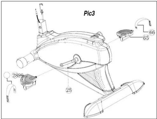
4. Pedal (See Pic3)
- Connect pedal belt (29, 66) to pedal (28, 65). See picture 3-A and 3-D.
- Lock the left pedal (28) to the left crank foot (25).
- Lock the right pedal (65) to the right crank foot.

natural_image
Close-up of a black mechanical clamp with a red arrow indicating rotation (no text or symbols visible)
natural_image
Close-up of a hand holding a black plastic object with a red arrow pointing to a small feature (no text or symbols visible)pic3-B
Pic3-A

natural_image
Close-up of a black plastic device with a red arrow indicating rotation or adjustment (no visible text or symbols)Pic3-C

natural_image
Technical line drawing of two mechanical or electrical components with no visible text or symbols5. Saddle (See pic4)
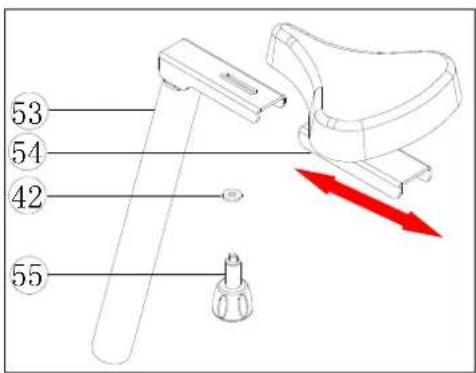
- First release the nut under the saddle (52), see picture 4-A; insert the saddle into the seat post (53), and lock it with the nut.
- Release the pull pin (39) and insert the seat post (53) into the main body, lock it up with the pull pin.
Seat horizontal adjustable
- First release the flat washer (42) and seat adjust knob (55) which are under the saddle (53).
- Adjust the position and lock it up with the removed washer and knob. See picture 4-B.

natural_image
Close-up of a mechanical component with a red annotation pointing to a circular feature, labeled 'Nvt' (no readable text or symbols beyond the label)Pic4-A

Pic4-B
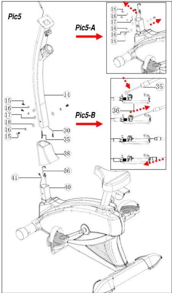
6. Computer post (See pic5)
- First remove the four screw M8*20(15), four M8 spring washer (16), two M8 arc washer (17) and two flat washer (18) which are pre-assembled on the main frame. See picture 5-A
- Rotate the TCD on the meter post (14) to the low Position, become the longest line to facilitate the connection.
- Insert the computer post housing (38) into the computer post.
- Attach the computer post (14) to the main frame (40), connect sensor wire upper (30) and lower (41).
Connect TCD upper part (35) to TCD lower part(36) See picture 5-B.
- Insert the computer post (14) to the main frame (40) Lock them with the removed screw and washer.
- Fix the computer post housing.
7. Computer (See Pic6)
- First remove the screws (2) which is pre-assembled on the computer (1)
- Connect the sensor wire up section (30) with sensor wire in the computer.
- Attach the computer (1) to the computer post (14) and lock it up with the removed screw (2).

8. Handle bar (See Pic7)
-
Fix the handle bar (4)the post, lock the rear handle bar housing (10) to the handle bar with screw M5*16 (12).
-
Lock the front housing (31) to the handle bar with handle bar knob(34), knob bushing (33)M8 spring washer (16) and flat washer (32).
-
Another screw M5*16 (12) to fix the front handle bar housing (31), then lock the front housing and rear housing with screw M4*20.
-
Insert the pulse line (9) into the socket on the computer backside.

9. Finished picture

natural_image
Line drawing of a stationary exercise bike with adjustable arms and legs (no text or symbols)EXPLODED DRAWING:

Parts list:
| No. | Name & specification Qty No. | Name & specification Qty | |||
| 1 | Computer | 1 | 44 | Crank axle bushing | 1 |
| 2 | Computer screw | 4 | 45 | R12 bearing | 2 |
| 3 | Handle bar end cap | 2 | 46 | Screw M8*20 | 2 |
| 4 | Handle bar | 1 | 47 | M8 nylon cap | 2 |
| 5 | Handle bar foam | 2 | 48 | Left rear stabilizer end cap | 1 |
| 6 | Hand pulse | 2 | 49 | Rear stabilizer | 1 |
| 7 | 50 | Left rear stabilizer rubber foot | 1 | ||
| 8 | Hand pulse screw | 4 | 51 | Screw M4*12 | 16 |
| 9 | Pulse lien | 1 | 52 | Saddle | 1 |
| 10 | Rear handle bar housing | 1 | 53 | Seat post | 1 |
| 11 | Screw M4*20 | 17 | 54 | Seat support tube | 1 |
| 12 | Screw M5*16 | 2 | 55 | Seat adjust knob | 1 |
| 13 | 1 | Right chain cover | 1 | ||
| 14 | Computer post | 1 | 57 | Belt plate bushing | 1 |
| 15 | Screw M8*20 | 4 | 58 | M6 nylon cap | 4 |
| 16 | M8 spring washer | 7 | 59 | M6 spring washer | 4 |
| 17 | Arc washer OD20*ID8.5*1.5T | 4 | 60 | Flat washer OD16*ID6.5*1.5T | 4 |
| 18 | Flat washer OD20*ID8.5*1.5T | 6 | 61 | Belt plate | 1 |
| 19 | Screw M8*72 | 2 | 62 | Crank axle set | 1 |
| 20 | Front moving wheel | 2 | 63 | Screw M6*18 | 4 |
| 21 | Front stabilizer | 1 | 64 | Right crank foot | 1 |
| 22 | Screw M3*12 | 2 | 65 | Right pedal | 1 |
| 23 | Left chain cover | 1 | 66 | Right pedal belt | 1 |
| 24 | Crank housing | 2 | 67 | Flat washer OD14*ID10.5*1.5T | 1 |
| 25 | Left crank foot | 1 | 68 | Adjust wheel | 1 |
| 26 | 5/16-18UNC25outer hexagon screw | 2 | 69 | Adjust roller bushing | 1 |
| 27 | Crank foot housing | 2 | 70 | M10 nylon cap | 1 |
| 28 | Left pedal | 1 | 71 | Spring | 1 |
| 29 | Left pedal belt | 1 | 72 | Screw M10*22 | 1 |
| 30 | Sensor wire up section | 1 | 73 | Adjust wheel fixer | 1 |
| 31 | Front handle bar housing | 1 | 74 | Gap washer | 1 |
| 32 | Flat washer OD12*ID8*1.5T | 1 | 75 | Flywheel axle washer | 1 |
| 33 | Handle bar knob bushing | 1 | 76 | Flywheel axle | 1 |
| 34 | Handle bar knob | 1 | 77 | Bearing 6901 | 1 |
| 35 | TCD Upper | part small belt plate 78 | 1 | ||
| 36 TCD Lower part 1 79 | one way bearing bushing | 1 | |||
| 37 | Belt | 1 | 80 | copper washer | 1 |
| 38 | Computer post housing | 1 | 81 | Bearing 6904 | 1 |
| 39 | Pull pin | 1 | 82 | One way bearing | 1 |
| 40 | Main frame | 1 | 83 | Flywheel | 1 |
| 41 | Sensor wire lower section | 1 | 84 | Bearing 6001 | 1 |
| 42 | Flat washer OD20*ID10.5*2.0T | 5 | 85 | Inner magnetic system | 1 |
| 43 | M10*6.35T nylon cap | 3 | 86 | Seat post bushing | 1 |
- Joy Sport Importeur
- Geachte klant,
- Montage:
- Zadel (zie tek 4)
- Joy Sport Importer
- Dear customer,
- Guarantee,
- Safety instruction to avoid any accident, we ask for your attention:
- Notes:
- Packing:
- Clear out the waster
- ASSEMBLING
- Front stabilizer (See Pic1)
- Rear stabilizer (See Pic2)
- Pedal (See Pic3)
- Saddle (See pic4)
- Seat horizontal adjustable
- Computer post (See pic5)
- Computer (See Pic6)
- Handle bar (See Pic7)
- Finished picture
Brand : Joy Sport
Model : HT-Golf
Category : Exercise bike