Experience - Exercise bike Joy Sport - Free user manual and instructions
Find the device manual for free Experience Joy Sport in PDF.


| Product Type | Exercise Bike |
| Brand | Joy Sport |
| Model | Experience |
| Dimensions (L x W x H) | 100 x 50 x 120 cm |
| Weight | 30 kg |
| Max User Weight | 120 kg |
| Resistance Type | Magnetic |
| Resistance Levels | 8 |
| Display | LCD with time, distance, speed, calories, pulse |
| Power Supply | Battery (2x AA) or optional AC adapter |
| Pedals | Adjustable with straps |
| Seat | Adjustable vertically and horizontally |
| Handlebar | Multi-grip with pulse sensors |
| Transport Wheels | Yes, for easy movement |
| Floor Stabilizers | Adjustable |
| Main Features | Silent magnetic system, ergonomic design, pulse monitoring |
| Maintenance | Periodic cleaning, check bolts, lubricate moving parts |
| Safety | Always attach safety clip, keep away from children, use on level surface |
| Spare Parts Available | Yes, contact Joy Sport support |
| Warranty | 2 years |
Frequently Asked Questions - Experience Joy Sport
User questions about Experience Joy Sport
0 question about this device. Answer the ones you know or ask your own.
Ask a new question about this device
Download the instructions for your Exercise bike in PDF format for free! Find your manual Experience - Joy Sport and take your electronic device back in hand. On this page are published all the documents necessary for the use of your device. Experience by Joy Sport.
USER MANUAL Experience Joy Sport
natural_image
Line drawing of a stationary exercise bike with adjustable arms and wheels (no text or symbols)Joy Sport Importeur
Fitness-Import
Timmermannsweg 46
5813 AP Ysselsteyn (LB)
info@joysport.nl
www.joysport.nl
Geachte klant,
5813 AP Ysselsteyn (LB)
info@joysport.nl
www.joysport.nl
Inhoud
- Veiligheidsvoorschriften ....1
- Doelstelling ...... 2
- Samenstellen ....2
Stukslijst :
natural_image
Line drawing of a stationary exercise bike with adjustable arms and wheels (no text or symbols)Opmerking
natural_image
Technical line drawing of a mechanical assembly with no visible text or symbolsnatural_image
Technical line drawing of a mechanical component with circular features and a numbered circle (24), no readable text or symbols present.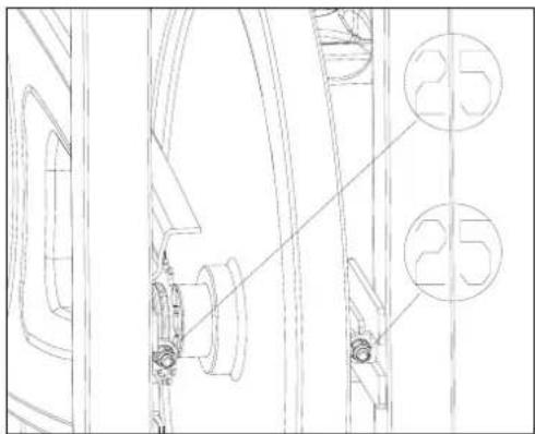
Dan is dit 220 minus 40 is 180 MAXIMALE HARTSLAG.
180 X 60% is 108 en 180 X 70% is 126.
natural_image
Line drawing of a stationary exercise bike with adjustable arms and wheels (no text or symbols)CONTENTS
- Safety Tips....1
- Features....2
- Installation....2
3.1 Dissection View ......2
3.2 List of parts....3
3.3 Assemble Guides....4
- Notice....8
Please read the following instructions before you start exercising with the equipment.
- The working area of the products is L2200*W1500*H2000mm. Keep children and pets away from the equipment when it is in use. No children operate or reach this equipment without adult guidance.
- Only one person should use the machine for one time.
- Wear suitable close, the loser clothes are easy twisted into the equipment, also please wear right shoes. Never use equipment barefooted.
- Equipment must be put in a clean and flat floor before exercise. Keep the machine away from water or don't leave it outside.
- Warm-up your body before exercising. If you experience dizziness, nausea, chest pain or other abnormal symptoms Stop your exercise immediately, and consult your physician. Don't do exercise before or after meal.
- To avoid injuries, never place any part of your body between or near any moving part.
- This equipment is only for home use, and it belongs to Class HB level
- The machine isn't suitable for medical treatment. The security of this equipment has passed EN957 certification
- The total weight of equipment is 45 Kg ± 0.5 Kg , the max loading weight is 120 Kg ± 0.5 Kg
- Stop using this machine and contact the supplier when the machine doesn't work normally.
- Please take off your clothing and footgear after finishing exercise, and clean them.
- Please use the machine following all instructions. Do not operate against instructions.
- Please pay much more attention when you uplift or move the machine so as not to injure your backside. Must move it in the right way or ask someone to help you.
Warning: Consult your physician before any exercise, and make sure you don't have health problem. Please keep this manual in order to check when necessary
Features & Basic information :
This exercise equipment belongs to Aerobic Exercise. This training objective is to increase oxygen inhaled and blood recycling, by long time training (stamina exercise). Active your heart blood cycling and lung breath system, so that all the organs of your body can get plenty
of oxygen and nutrition. Thus the whole body maintains in a good state of fitness.
The equipment is designed according to the drive theory of bicycle; the resistance adopts friction theory. Adjust the resistance by tuning the knob, and brake by using the speediness handle. The equipment is safety during the exercise. It is suitable for use in home, office, inn and clubs.
- Make sure the equipment is stable, before you start to exercise. If the ground isn't plain, you can adjust four adjustable feet (17) to plain state
- By adjusting the height of stand pipe (10), slide the seat support pipe (11) to a proper position, after that please adjust the height of gripe (19) according to your body size.
- Set the right resistance for yourself by adjusting tuning knob (14). You may do exercise three times every week, very time it takes an hour to exercise, the best working effect is that the HBF reaches 110-150 times/min.
- The drive mode equipment is bi-directive drive. Please press speediness handle to brake, when aggressive exercise is performed, it will stop immediately. Never leave the seat pad until all the working parts are completely stopped.
Installation
Step 1: According the drawing and parts list, take out all the parts from carton.

Part List :
| List of parts | ||
| No. | Description | |
| 1 M10 nut cap 4 | ||
| 2 M10 flat mat 6 | ||
| 3 | M10XL45mm screw | |
| 4 | Main support | |
| 5 Back bottom pipe 1 | ||
| 6 Front bottom pipe 1 | ||
| 7 | Water jug | |
| 8 | Pedals | 各1 |
| 9 Water jug support 1 | ||
| 10 Seat stand pipe 1 | ||
| 11 | Seat support pipe | 1 |
| 12 | Seat | 1 |
| 13 | Adjusting screw | 3 |
| 14 | Adjusting | knob |
| 15 | Speedless | handle |
| 16 | Pulley | |
| 17 | Adjusting | |
| 18 | Fixup | pipe |
| 19 | Gripe | |
| 20 M10X22 Hexagonal Screw 2 | ||
| 21 M5X12 Cross-head Screw 2 | ||
| 22 M5 Flat Mat 2 | ||
| 23 | Friction-flake | |
| 24 M12XP1.0 nut cap 2 | ||
| 25 M6 Nylon Nut 2 | ||
| 26 | 13# ~ 15 # open spanner | 1 |
| 27 | 14#~17 # open spanner | 1 |
| 28 | 6mm Hexagonal | |
| 29 | 5” Cross-head Screwdriver | 1 |
feet
Spanner
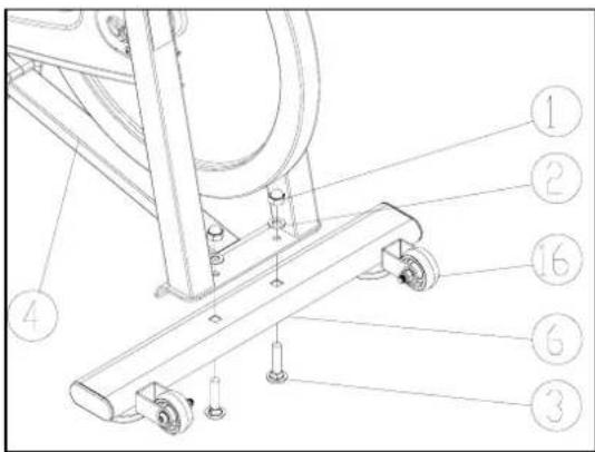
Step 2: According to the following Fig, fix the back bottom pipe (5) to the main support (4) by using M10XL45mm screw (3), flat mat (2) and M10 nut cap (1)

Step 3: Fix the front bottom pipe (6) to the main support (4) by using M10XL45mm screw (3), flat mat (2) and M10 nut cap (1), referring to the following Fig, and then fasten all the screws,
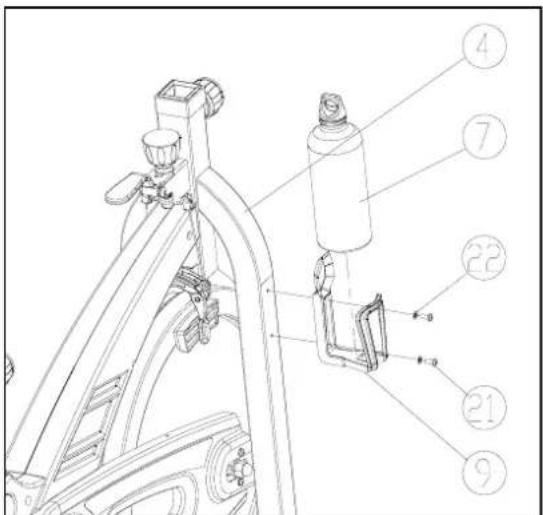
Step 4: Assemble the water jug support (9) to main support (4), and fix by M5 flat mats (22), M5*12 cross-head screws(21), then lay the water jug. As the following Fig
Step 5: Insert the right and left pedals(8) to the crank, then use the 15 # open spanner to fasten. Refer to the following Fig,

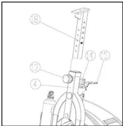
Step 6: Loose the adjusting screw (13), and insert the fixup pipe (18) to the top square pipe of main support (4), then choose the right height and fasten. Refer to the following Fig.
Step 7: Assemble the gripe(19) to fixup pipe by using 6mm Hexagonal Spanner, M10X22 Hexagonal Screw(20) with M10 flat mats(2).As the following Fig.

Step 8: Turn the adjusting screw (13), and insert the seat stand pipe (10) to the main support (4), and screw down the adjusting screw (13). Before adjusting the height, make sure the adjusting screw (13) is loose, and then choose the right height between gripe and seat support pipe, and fix the adjusting screw (13). As per the following Fig.
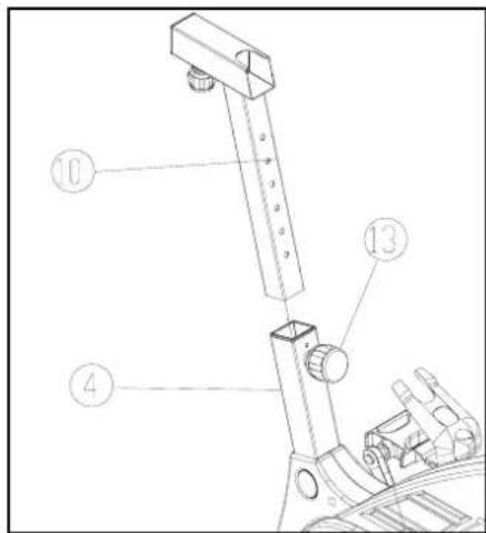
Step 9: Pull the adjusting screw (13), and insert seat support pipe (11) to seat stand pipe (10), then fasten. as per the below Fig, insert seat pad(12) to seat support pipe(11), then use13# open spanner

Step 10: When installation is finished, please carefully check all the screws and nuts fastened or not.

natural_image
Line drawing of a stationary exercise bike with adjustable arms and wheels (no text or symbols)Notice
-
Check all the nuts, nut caps and pedals in securing state regularly. If you find any defective parts, don't do any exercise until you repair well.
-
Pay more attention to easy damage parts, for instance friction-flake (23), if you find it doesn't work or fall off, replace it. As the following Fig

natural_image
Technical line drawing of a mechanical assembly with no visible text or symbols- If you find the chain is loosing, as the following Figs, loose M12*P1.0 nut cap(24), and adjust M6 Nylon nut(25) by using 10mm-sleeve-spanner.When you feel it is ok, fasten M12*P1.0 nut cap(24).

natural_image
Technical line drawing of a mechanical component with circular features and a numbered circle (24), no readable text or symbols present.
Brand : Joy Sport
Model : Experience
Category : Exercise bike