HT-Excellent - Exercise bike Joy Sport - Free user manual and instructions
Find the device manual for free HT-Excellent Joy Sport in PDF.


| Product Type | Exercise Bike |
| Brand | Joy Sport |
| Model | HT-Excellent |
| Maximum User Weight | 100 kg |
| Power Supply | 200-240V ~ 50/60Hz |
| Resistance Levels | 16 |
| Display | LCD with Time, Distance, Speed, RPM, Calories, Pulse, Watt, Recovery, Body Fat |
| Programs | Manual, Program (12 profiles), User (custom), Target Heart Rate |
| Pulse Measurement | Handgrip sensors (conductive) and optional chest strap |
| Seat Adjustment | Horizontal (forward/backward) and vertical via seat post knob |
| Handlebar Adjustment | Tilt adjustment via knob |
| Transport Wheels | Yes (front) |
| Water Bottle Holder | Yes, included with bottle |
| Pedals | Adjustable straps |
| Frame Material | Steel |
| Assembly Required | Yes, with tools included |
| Warranty | 12 months |
| Safety Approvals | TÜV Rheinland Product Safety |
| Space Required (approx.) | 2 x 1 meters |
| Net Weight (approx.) | 35 kg |
| Product Dimensions (L x W x H) (approx.) | 110 x 55 x 130 cm |
Frequently Asked Questions - HT-Excellent Joy Sport
User questions about HT-Excellent Joy Sport
0 question about this device. Answer the ones you know or ask your own.
Ask a new question about this device
Download the instructions for your Exercise bike in PDF format for free! Find your manual HT-Excellent - Joy Sport and take your electronic device back in hand. On this page are published all the documents necessary for the use of your device. HT-Excellent by Joy Sport.
USER MANUAL HT-Excellent Joy Sport
natural_image
Line drawing of a stationary exercise bike with adjustable arm and control panel (no text or symbols)
TÜV Rheinland Product Safety


Joy Sport Importeur
Fitness-Import
Timmermannsweg 46
5813 AP Ysselsteyn (LB)
info@joysport.nl
www.joysport.nl
Geachte klant,
5813 AP Ysselsteyn (LB)
info@joysport.nl
www.joysport.nl
2 Voor stabilisator

natural_image
Close-up of a hand holding a black handheld device with a red arrow indicating rotation (no text or symbols visible)Photo 4-A

natural_image
Close-up of a hand holding a black plastic clip with a red arrow pointing to the clip (no text or symbols visible)Photo 4-B

natural_image
Close-up of a black mechanical device with a red circular arrow indicating rotation (no text or symbols visible)Photo 4-C
natural_image
Technical line drawing of two mechanical components with no visible text or symbols5 Zadel

6 Stuurkolom
natural_image
Close-up of a metallic mechanical component with threaded shaft and bolted end (no visible text or symbols)Photo 8-A

9 Bidonhouder

natural_image
Line drawing of a stationary exercise bike with attached sensor and power plug (no text or symbols)Onderdelenlijst.
| NR. | Naam en Specificatie Aantal. | NR. | Naam en | Specificatie Aantal. | |
| 1 | Computer | 1 42 | Computer kabel 1 | ||
| 2 | Schroefjes M5* 12 | 4 | 43 | Plastic bus | 1 |
| 3 | Afdichtdopje | 2 | 44 | Zadelknop | 1 |
| 4 | Stuur | 1 | 45 | motor | 1 |
| 5 | Foam | 2 | 46 | Kabel | 1 |
| 6 | Handgreepsensoren | 2 | 47 | Hoofdframe | 1 |
| 7 | Foam | 2 | 48 | Kabel | 1 |
| 8 | M3* 10 schroefjes | 6 | 49 | Lager R12 | 2 |
| 9 | Kabel handgreepsensoren | 1 | 50 | Borgveer | 1 |
| 10 | Beschermkapje | 1 | 51 | M10* 6.35T Borgmoer | 2 |
| 11 | M4* 20 schroefjes | 20 52 | M8* 20 Bout | 2 | |
| 12 | M5* 16 bout | 5 | 53 | M8 Borgmoer | 1 |
| 13 | Beschermkapje | 1 | 54 | Achter stabilisator beschermkapje (L) | 1 |
| 14 | Stuurkolom | 1 | 55 | Achter Stabilisator | 1 |
| 15 | M8* 20 inbusbout | 4 | 56 | Rubber beschermkapje (L) | 1 |
| 16 | M8 veerring | 7 | 57 | M4* 12 bout | 16 |
| 17 | OD20* ID8.5* 1.5T gebogen ring | 4 | 58 | Achter stabilisator beschermkapje (R) | 1 |
| 18 | D20* ID8.5* 1.5T ring | 4 | 59 | Rubber beschermkapje (R) | 1 |
| 19 | M8* 72 inbusbout | 2 60 | V-riem geleider busje 1 | ||
| 20 | Transportwieltjes | 2 | 61 | M6 Borgmoer | 4 |
| 21 | Voor stabilisator | 1 | 62 | Veerring | 4 |
| 22 | Afdichtring | 1 | 63 | OD16* ID6.5* 1.5T Ring | 4 |
| 23 | Linker pedaal bandje | 1 | 64 | V-riem geleider met magneet | 1 |
| 24 | Linker pedaal | 1 | 65 | Crank as | 1 |
| 25 | Crank dopje | 1 | 66 | M6* 18 Bout | 4 |
| 26 | 5/16-18UNC25 bout | 2 | 67 | V-riem | 1 |
| 27 | Linker crank | 1 | 68 | Magneet | 1 |
| 28 | Afdichtring (crank) | 2 | 69 | Borgmoer | 1 |
| 29 | Linker beschermkap | 1 | 70 | V-riem geleider met lager 6000 | 1 |
| 30 | Computer kabel | 1 | 71 | Busje | 1 |
| 31 | OD12* ID8* 1.5T Ring | 1 | 72 | Borgveer | 1 |
| 32 | Busje | 1 | 73 | Ring | 1 |
| 33 | Stuurknop | 1 | 74 | Spanner | 1 |
| 34 | Zadel | 1 | 75 | Veer | 1 |
| 35 | Bidonhouder | 1 | 76 | Ring | 1 |
| 36 | Bidon | 1 | 77 | Rechter beschermkap | 1 |
| 37 | Zadelsleede | 1 | 78 | Rechter pedaal met bandje | 1 |
| 38 | OD20* ID10.5* 2.0T Ring | 4 | 79 | Rechter pedaal | 1 |
| 39 | Zadelknop | 1 | 80 | Rechter crank | 1 |
| 40 | Zadelpen | 1 | 81 | Adaptor | 1 |
| 41 | Beschermkapje | 1 | |||
Computer Handleiding
natural_image
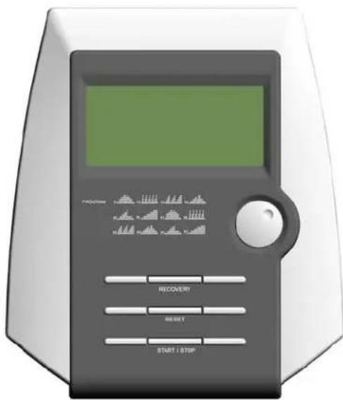
Front view of a portable electronic device with control buttons and a green screen (no visible text or symbols)Werking computer
Inschakelen
Watt 0 - 999 watts 0 - 350 watts
Kalorie 0 - 9999 cal 0 - 9999 cal
Hartslag 30 - 240 bpm 30 - 240 bpm
Recuperatie F1 - F6
Geen
Dan is dit 220 minus 40 is 180 MAXIMALE HARTSLAG.
180 X 60% is 108 en 180 X 70% is 126.
natural_image
Line drawing of a stationary exercise bike with adjustable arms and legs (no text or symbols)
5813 AP Ysselsteyn (LB)
info@joysport.nl
www.joysport.nl
Dear customer,
We want to thank you for having chosen a JOY SPORT product, and wish you a lot of fun and
success during training with your JOY SPORT exercisers.
Please note and follow the enclosed safety and assembly instructions carefully.
If you have questions please do not hesitate to contact us.
Guarantee,
This guarantee covers all manufacturing and material flaws on JOY SPORT products purchased from an authorized JOY SPORT dealer for a period of 12 months from purchase.
If you wish to make a claim under the guarantee, JOY SPORT shall be entitled to repair or replace the defective unit or part at its discretion.
The owner of the unit must pay for the transport costs and any dealer's workshop costs.
To make a claim under the guarantee, take your guarantee card to your dealer.
The dealer will then take the necessary action.
If this is not possible, contact your national JOY SPORT importer.
The following are not covered by the guarantee: normal wear and tear and the consequences of improper treatment or damage caused by the purchaser or third persons and faults which are due to other circumstances.
Claims may not be made under the guarantee if modifications have been made to the original construction or equipment or if JOY SPORT original parts were not used to repair the unit.
In no event the manufacturer shall be liable for incidental or consequential losses, damages or expenses in connection with exercise products.
Fitness-Import
Timmermannsweg 46
5813 AP Ysselsteyn (LB)
info@joysport.nl
www.joysport.nl
General safety instructions
In the design and the production of this fitness equipment, much attention has been paid to safety. Nevertheless, you need at all times to remain conscious of certain safety measures. Make certain that you have carefully read through the whole user manual prior to your use of the equipment. Keep in mind the following points:
- This equipment has not been designed to be used as a toy and must only be used for the purposes described in this manual. Read the instructions below carefully before using this equipment.
- Keep children and animals away from the equipment. Children's enthusiasm may well lead to incorrect use of the equipment. If children are allowed to use the equipment, they should only do so under supervision and after receiving instructions regarding its proper use. Under no circumstances should the equipment be used as a toy.
- Always consult with your physician prior to making use of this equipment or any other fitness equipment.
- Always wear safe and comfortable clothing when you are using fitness equipment. Preferably, wear sports shoes or aerobic footwear.
- In the event you should feel faint or suffer other discomforts, stop using the equipment. You also need to stop when you experience pain in or pressure on your joints.
- Make certain that no more than one user is occupying the equipment at one time. Place the equipment on a level surface; the space required is approximately 2 x 1 meters.
- Make certain that the equipment has been correctly assembled prior to its use. Ensure that all screws, nuts and bolts have been fitted correctly and tightened properly. Use only the parts that are recommended by the importer and that have been delivered with the equipment.
- Do not use the equipment if it is damaged or has broken down.
- Pay attention to how your body reacts after using the equipment. Dizziness is a sign that you worked out too intensely. If you feel dizzy, stretch out on the floor and do not try to get back on your feet until the dizziness has disappeared.
- Always use the equipment on a level and clean surface. Never use the equipment outdoors or in water.
- Avoid that your arms and legs come too close to the moving parts. Do not stuff articles inside the existing openings in the equipment.
- Use this equipment only for the purposes as described in this user manual. Do not use parts that were not recommended by the manufacturer.
- Ascertain that there are no sharp and pointed objects in the immediate vicinity of the equipment.
- We advise physically challenged individuals to use this fitness equipment only under the supervision of qualified instructors.
- The equipment must have come to a complete standstill before stepping down.
Warning
Consult with your physician prior to starting your exercises. A frequent and intensive training programme should first be approved by your family physician. This is especially important for individuals above 35 years of age or for those with physical problems. Carefully read through the entire user manual before you start exercising. We are in no wise responsible for personal injury or physical strains and discomforts that are caused by the use of this equipment and cannot be held liable in case of their occurrence. Carefully save these instructions. Incorrect or extreme use may lead to personal injury.
Note: the maximum permissible weight on this equipment is 100 kg.
Assembly
This user manual has been put together in order to simplify the assembly of the equipment and at the same time to explain its correct use. Please make certain to carefully read through this manual. In order to familiarise yourself with the parts of the equipment, we recommend that you carefully study the general reference drawing prior to starting the assembly and the use of the equipment.
Place all parts needed for the assembly on the floor in an orderly manner and remove all packing material. Check the list of parts to verify what items are present. For the actual assembly we make referral to the following pages.
Thank you for your purchase
we thank you for your purchase of this fitness equipment. This equipment will help you in improving your general conditioning and in developing your muscles in the correct way. In addition, you can now enjoy all of these benefits inside your own home.
Maintenance and use
Consult your physician before starting the exercises. A frequent and strenuous workout program must be approved by your physician first.
- The equipment requires a regular check-up to prevent physical injury. This means that bolts and nuts should be frequently checked for their proper tightening and that the equipment in general should be checked for cracks and sharp edges etc.
- Defective components must be replaced immediately. If this is not feasible, the equipment must be put out of order until the required repairs have been made.
- NB! Do not smoke or use fire near the equipment, as some of the plastic components are flammable.
- Do not use the equipment in front of a burning stove and/or fire place.
- Persons suffering from a plastics allergy should consult their physician before using the equipment.
- Do not touch any cylinders on the equipment as they become extremely hot during use.
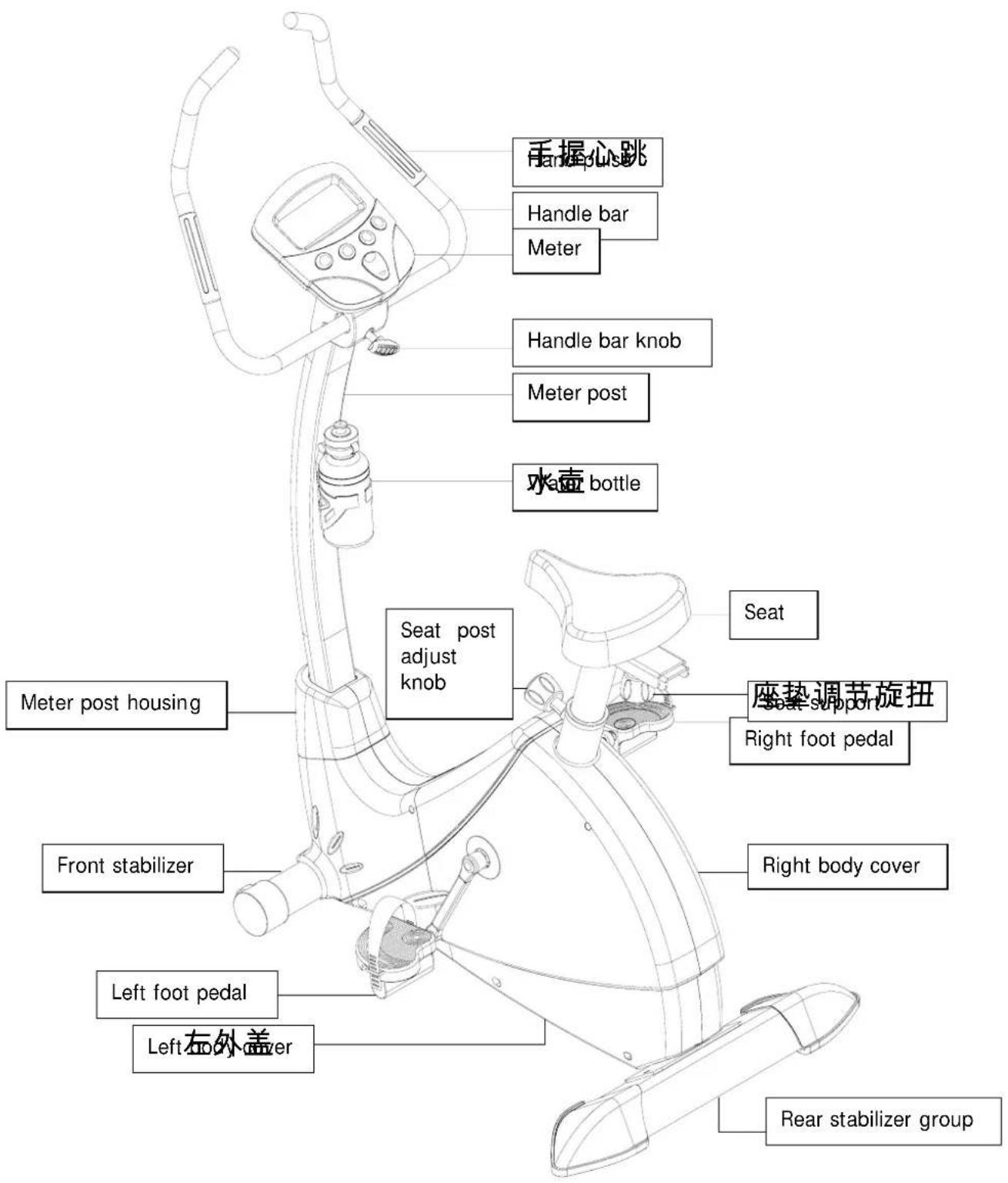
1. Parts & Tools
Please review the following photos to identify the tool you will use for assembly.
| Nr. | Name & Specs Photo Qty | . | Nr. | Name & Specs Photo Qty | . | ||
| 11 | M4* 20 cross screw |  | 1 | 32 | handle bar knob tube bushing |  | 1 |
| 12 | M5* 16 round cross screw |  | 4 | 33 | handle bar knob | 1 | |
| 16 | M8 spring washer |  | 3 | 52 | M8* 20 carriage screw | 2 | |
| 17 | M8 arc washer |  | 2 | 53 | M8 nylon cap |  | 2 |
| 18 | OD20* ID8.5* 1.5T flat washer | 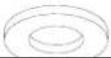 | 2 | 5MM inner hexagon spanner |  | 1 | |
| 19 | M8* 72 inner hexagon screw | 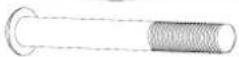 | 2 | Tri-functional spanner | 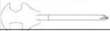 | 1 | |
| 31 | OD12* ID8* 1.5T flat washer |  | 1 | Tum spanner | 1 |

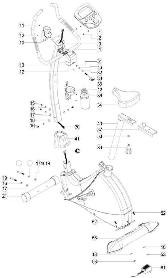
ASSEMBLY EXPLODED DIAGRAM
2 FRONT STABILIZER
Take the front stabilizer (21) close to the front bottom of main frame. Inert through a M8 spring washer (16), M8 arc washer (17) with an M8*72 innerhexagon screw (19) and lock the up on the stabilizer.
3 REAR STABILIZR GROUPP
Attach the rear stabilizer group (55) on the rear bottom of the main frame. Insert through an M8* 20 carriage screw (52) and use OD20* ID8.5* 2.0T flat washer (18), M8 nylon cap (53) to lock them up.
4 PEDALS
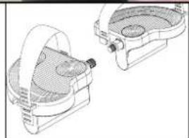
Please fix the pedal bondage (23, 78) onto the pedals (24, 79) according to the photo illustration 4-A / 4-B / 4-C
Screw the left pedal (24) with bondage anti-clockwise so that it will get connected firm with left crank (27)
Then screw the right pedal (78) with bondage clockwise so that it will get connected firm with right crank (79).


natural_image
Close-up of a hand holding a black mechanical device with a red arrow indicating rotation (no text or symbols visible)Photo 4-A

natural_image
Close-up of a hand holding a black plastic clip with a red arrow pointing to the clip (no text or symbols visible)Photo 4-B

natural_image
Close-up of a black plastic device with red adjustment knob, held by a finger (no visible text or symbols)
natural_image
Technical line drawing of two mechanical components with no visible text or symbolsPhoto 4-C
5 SEAT
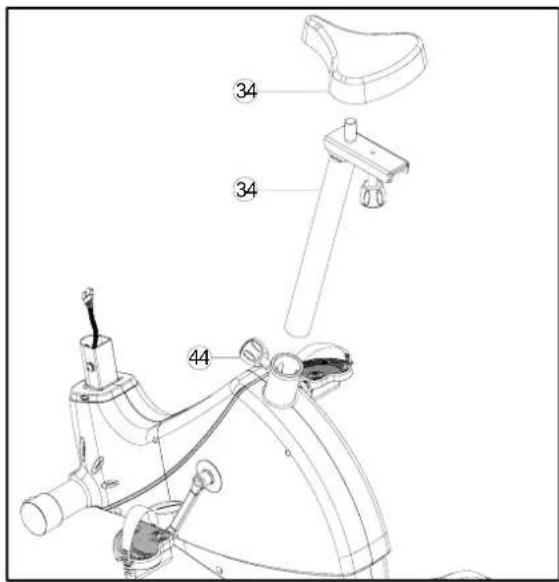
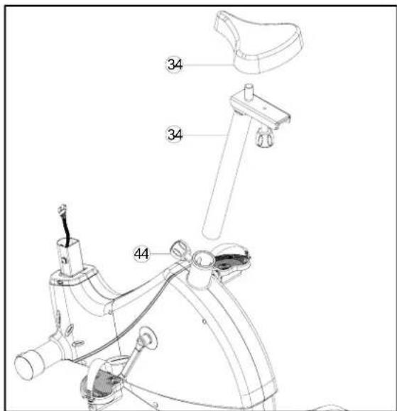
First loosen the nuts which are fixed with the seat (34) please refer to photo illustration 5-A. Then slide the seat (34) on the seat group (34). Tighten the loosen nuts.
Pull out the seat post knob (44) and hold on. Insert the seat group (34) into the main frame. Set it on your wanted position and release the seat post knob. Screw it to firm. Please make sure the seat post knob (44) must be inserted through the holes inside the seat post and screwed without any gap.
SEAT ADJUST
You can adjust your seat forward or backward.
Loosen the seat adjust knob (39) & OD20* ID10.5* 2.0T flat washer (38).
Then you can move the seat support (37) forward or backward so that seat position could be changed accordingly as your level. Finally tighten the knob again. (Photo 5-B)


6 METER POST
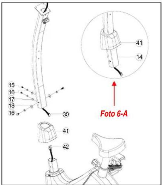
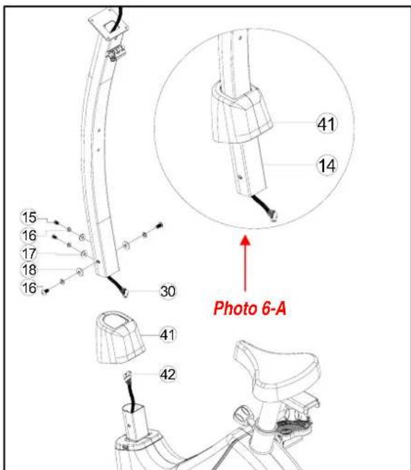
Remove the four M8* 20 inner hexagon screws (15), four M8 spring washers (16), two M8 arc washers (17) and two OD20* ID8.5* 1.5T flat washers (18) which are pre-assembled meter post.
Move the meter post housing (41) at upper position of the meter post (14). Please refer to the Photo 6-A. Then move the meter post (14) close to the lower post. Combine the meter connecting upper wire (30) with meter connecting lower wire (42)
Then insert the meter post into lower post. Lock them with the removed screws & washers.
Finally fix the meter post housing on the main frame.
7 METER
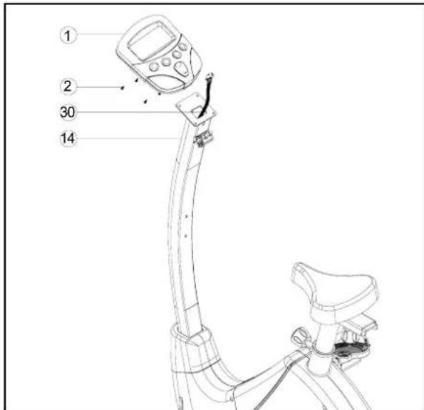
Remove the meter screws M5* 12 (2) from the back of the meter (1).
Combine the meter connecting upper wire (53) with meter wire at back of the meter.
Attach the meter (1) on the top site of the meter post (14) and use the removed meter screws M5* 12 to lock them up.
8 HANDLE BAR & HOUSING.
Put the handle bar (9) into the handle bar fixer. Cover a handle bar rear housing (10) and use an M5* 16 cross screw (12) to lock it.
Cover the handle bar front housing (13).Adjust the handle bar at a proper angle so that you can insert the handle bar knob (33) through handle bar knob tube bushing (32), M8 spring washer (16) and OD12* ID8* 1.5T (31).. Screw the knob to fix them all up on the handle bar. Please refer to the Photo 8-A.
Then use an M5* 16 cross screw to fix a the handle bar front housing. Use an M4* 20 cross screw to fix together with handle bar front housing (13) and handle bar rear housing (10).
Plug the hand pulse wire (9) into the sensor hole on back side of the meter.

natural_image
Close-up of a metallic mechanical component with threaded shaft and bolt (no visible text or symbols)Photo 8-A


9 WATER BOTTLE
Attach the water bottle holder (35) on the meter post. Use M5* 16 round cross screw (12) to fix them.
Insert the water bottle (36) into the holder.


natural_image
Line drawing of a stationary exercise bike with attached sensor and control panel (no text or symbols)10 POWER SUPPLY
Please make sure the transformer is connected with your country's power standard (200-240V \~ 50/60Hz).
Meter can be operated immediately only under this power supply.
EXPLODED DIAGRAM

PARTS LIST.
| NR。 | NAME & SPECS QTY. NR. NAME & | SPECS | QTY. | ||
| 1 | meter | 1 42 | meter | connecting lower wire 1 | |
| 2 | meter screws M5*12 | 4 43 | seat post bushing 1 | ||
| 3 | handle bar end caps | 2 | 44 | seat post adjust knob | 1 |
| 4 | handle bar | 1 | 45 | motor | 1 |
| 5 | handle bar foam 1 | 2 | 46 | sensor wire with sensor and fixer | 1 |
| 6 | handle pulse | 2 | 47 | main frame | 1 |
| 7 | handle bar foam 2 | 2 | 48 | moter piano wire | 1 |
| 8 | hand pulse round cross M3*10crew | 6 | 49 | bearing R12 | 2 |
| 9 | hand pulse wire | 1 | 50 | crank axle semicircular wahser withΦ19 | 1 |
| 10 | handle bar rear housing | 1 | 51 | M10*6.35T nylon cap | 2 |
| 11 | M4*20 cross screw | 20 52 | M8*20 carriage screw | 2 | |
| 12 | M5*16 round cross screw | 5 | 53 | M8 nylon cap | 1 |
| 13 | handle bar front housing | 1 | 54 | rear stabilizer end cap (L) | 1 |
| 14 | meter post | 1 | 55 | rear stabilizer group | 1 |
| 15 | M8*20 inner hexagon screw | 4 | 56 | rear end cap rubber washer (L) | 1 |
| 16 | M8 srping washer | 7 | 57 | M4*12 cross screw | 16 |
| 17 | OD20*ID8.5*1.5T arc washer | 4 | 58 | rear stabilizer end cap (R) | 1 |
| 18 | D20*ID8.5*1.5T flat washer | 4 | 59 | rear end cap rubber washer (R) | 1 |
| 19 | M8*72 inner hexagon screw | 2 60 | belt plate gap bushing 1 | ||
| 20 | front transportation wheel | 2 61 | M6 nylon cap 4 | ||
| 21 | front stabilizer | 1 | 62 | spring washer | 4 |
| 22 | seat post housing | 1 | 63 | OD16*ID6.5*1.5T flat washer | 4 |
| 23 | left pedal bandage | 1 | 64 | belt plate with magnet sensor | 1 |
| 24 | left pedal | 1 | 65 | crank axle group | 1 |
| 25 | crank foot cover | 1 | 66 | M6*18 outer hexagon screw | 4 |
| 26 | 5/16-18UNC25 outer hexagon screw | 2 | 67 | belt | 1 |
| 27 | left crank | 1 | 68 | inner magnet group | 1 |
| 28 | crank housing | 2 | 69 | nylon cap | 1 |
| 29 | left body cover | 1 | 70 | arc adjust wheel with bearing 6000 | 1 |
| 30 | meter connection upper wire | 1 | 71 | adjust wheel tube bushing | 1 |
| 31 | OD12*ID8*1.5T flat washer | 1 | 72 | flywheel axle semicircular withΦ12 | 1 |
| 32 | handle bar knob tube bushing | 1 | 73 | gap washer | 1 |
| 33 | handle bar knob | 1 | 74 | adjust wheel fixer | 1 |
| 34 | seat | 1 | 75 | adjust spring | 1 |
| 35 | water bottle holder | 1 | 76 | curve washer | 1 |
| 36 | water bottle | 1 | 77 | right body cover | 1 |
| 37 | seat support | 1 | 78 | right pedal bandage | 1 |
| 38 | OD20*ID10.5*2.0T flat washer | 4 | 79 | right pedal | 1 |
| 39 | seat adjust knob | 1 | 80 | right crank | 1 |
| 40 | seat post | 1 | 81 | transformer | 1 |
| 41 | meter post housng | 1 | |||
Computer Instructions

Operating Instructions Computer
Switch on
After connecting the power adapter and/or after pressing any button the display will be blinking for some seconds showing the figure 78, then displaying "U1", which stands for user 1. This computer has a 9 users memory feature. Use button "UP" to select "U2 up to U9". Use button "ENTER" to exit user set-up.
Next the display shows "P"(pause), "PROGRAM", "USER" and "TARGET H.R". Use button "UP" to select the appropriate program. Use button "ENTER" to confirm selection.
Function buttons
ENTER Press to select any function to be displayed on the main screen.
ST/STOP To start or stop the exercise program.
RECOVERY Press this button for recovery function: After exercising, while the LCD is still active, press recovery button, and hold both sensors (or wear the chest transmitter) The computer will run a time down for 60 seconds, after which your recovery rate will be displayed, grades 1 up to 6. Level 1 featuring fast recovery, level 6 slow recovery.
BODY FAT Enter your personal data Put both hands straight and hold the grip pulse sensor for about 15 seconds and your Body Fat Value will be displayed in the Body Fat window. Since male and female fat structure is different, t
the evaluation should also be different. Check the reference list shown below.
RESET To clear the display and reset all data. Press for 3 seconds to clear all data, the display will show 'U1'. Press for 1 second to clear last single entry or one single display.
UP To select upward function.
DOWN To select downward function
Function description
Time:
Displays time function by pressing the ENTER button (marking – flashes in "TIME" lcd window). For countdown enter rate in minutes by pressing the up/down button.
Distance:
Displays distance function by pressing the ENTER button (marking – flashes in "DISTANCE" Icd window). For countdown enter rate in km by pressing the up/down button.
Calories:
Displays calorieburn function by pressing the ENTER button (marking – flashes in "CALORIE" lcd window). For countdown enter rate by pressing the up/down button.
Speed:
Displays speed function by pressing the ENTER button (marking – flashes in "SPEED" lcd window).
Rpm:
Displays Rpm function by pressing the ENTER button (marking – flashes in "RPM" lcd window.)
Watt:
Displays power value function by pressing the ENTER button (marking – flashes in "WATT" Icd window.)
Pulse:
Hold firmly both sensors on the handgrip (please wipe sensors and hands before starting measuring your pulse) or apply optional cheststrap (moisten slightly the contacts of the strap). Your current heart rate will be displayed within 30 seconds up to one minute. A stable figure requires to hold both sensors firmly.
Function value range
Functions Display Range Preset Range
Speed 0.0 - 99.9 km/h None
RPM 20 - 999 rpm None
Time 00.00 - 99.59 min 01.00 - 99.00 min
Distance 0.00 - 99.99 km 0.5 - 99.50 km
Watt 0 - 999 watts 0 - 350 watts
Calories 0 - 9999 cal 0 - 9999 cal
Pulse 30 - 240 bpm 30 - 240 bpm
Recovery F1 - F6 None
Training in MANUAL mode
- Select "MANUAL", use "UP" and "DOWN" button to adjust the load level (this ergometer offers 16 levels), confirm selection by pressing "ENTER".
- "TIME" flashes: use "UP" and "DOWN" button to set exercise time, confirm selection by pressing "ENTER". If you donot intend setting exercise time, simply press "ENTER".
- "DISTANCE" flashes: use "UP" and "DOWN" button to set distance, confirm selection by pressing "ENTER". If you donot intend setting exercise distance, simply press "ENTER".
- "CALORIES" flashes: use "UP" and "DOWN" button to set calorie consumption, confirm selection by pressing "ENTER". If you donot intend setting calorie consumption, simply press "ENTER".
- "WATT" flashes: use "UP" and "DOWN" button to set target watts, confirm selection by pressing "ENTER". The tension difficulty will be auto-adjusted according to the Watt figure. If the figure is under the target value, the tension difficulty will be up-adjusted one level every 30 seconds, up to the maximum level 16. As soon as you achieved the set value, tension difficulty will be down adjusted one level immediately. In case of overspec the level will be down adjusted one level immediately, and keep down-adjusting each 15 seconds until you reach the preset value. If you donot intend setting Watts, simply press "ENTER".
- "PULSE" flashes: use "UP" and "DOWN" button to set maximum heart rate, confirm selection by pressing "MODE". If you donot intend setting a heart rate level, simply press "ENTER", the monitor will display current heart rate value.
- Start exercising by pressing the "ST/STOP" button.
Training in PROGRAM mode
- Select "PROGRAM", use "UP" and "DOWN" button to select profile 1 to 12, confirm selection by pressing "ENTER".
- Press "ENTER" again, and set target value for 'TIME, DISTANCE, CALORIES AND PULSE'. Follow the procedure as described above in manual mode. In program mode "WATT" cannot be preset.
- If you donot intend setting any target value, start exercising by pressing the "ST/STOP" button.
Training in USER mode
- Select "USER", use "UP" and "DOWN" button to set up your own profile (this ergometer offers 16 load levels and 16 load segments).
- In each segment confirm your loadsettings by pressing "ENTER".
- Start exercising directly by pressing the "ST/STOP" button, or if you intend to set personal target values, press the "ST/STOP" button once again. "P" and "TIME" are flashing. Follow the procedure as described above in manual mode for presetting target values.
- Start exercising by pressing the "ST/STOP" button.
Training in TARGET H.R. mode
- Select "TARGET H.R.", use "UP" and "DOWN" button to enter your age.
- Press "ENTER", "55%" is flashing. Use "UP" and "DOWN" button to select 55, 75, 90 or THR. Confirm your selection by pressing "MODE".
- If you selected 55, 75 or 90%, "TIME" is flashing: follow the procedure as described above in manual mode for presetting target values.
- If you selected THR, "100" is flashing: use "UP" and "DOWN" button to set target heart rate.
- Confirm your selection by pressing "ENTER".
- Start exercising by pressing the "ST/STOP" button.
- Upon entering rate in Bpm (Beats per minute) the load tension will be controlled by current heart rate. The resistance will be auto-adjusted according to current heart rate figure. If your heart rate figure is under the target pulse, the tension will be up-adjusted one level every 30 seconds, up to the maximum level 16. As soon as your heart rate figure has achieved the target pulse, tension will be down adjusted one level immediately. In case of overspec the level will be down adjusted one level immediately, and keep down-adjusting each 15 seconds until your heart rate figure has achieved the target pulse.
To reselect initial mode push "STOP" (LCD shows "P" in top left). Press "RESET" and use "UP" and "DOWN" button to select another program mode.
The display will shut down automatically after 4 minutes of non-activity.
Training Instructions
If you have not been physically active for a long period of time and also to avoid health risks you should consult your general physician before starting to exercise.
To achieve a considerable improvement of your physical resistance and your health, some aspects of how to achieve the most efficient training should be followed:
Intensity
To achieve maximum results the right intensity has to be chosen. The heart rate is used as guideline. As a rule of thumb the following formula is commonly used:
Maximum pulse rate = 220 - Age
While exercising the pulse rate should always be between 60% - 85% of the maximum pulse rate.
For your personal training rates please see the attached pulse rate chart.
When starting to exercise you should keep your rate at 70% of your maximum pulse rate in the first couple of weeks.
With increasing improvement of fitness the pulse rate should be slowly increased to 85% of your maximum pulse rate.
This is a personal orientation value. Consult your physician for professional advise before adapting a heart rate recovery program.
Fat burning
The body starts to burn fat at approx. 65% of the maximum pulse rate. To reach an optimum at burning rate, it is advisable to keep the pulse rate between 70% – 80% of the maximum pulse rate. The optimum training amount consists of three workouts per week 30 minutes each.
Example:
You are 52 years of age and would like to start exercising. Maximum pulse rate = 220 - 52(age) = 168 pulse/min Minimum pulse rate = 168 x 0.7 = 117 pulse/min Highest pulse rate = 168 x 0.85 = 143 pulse/min
During the first weeks it is advisable to start with a pulse rate of 117, afterwards increase it to 143. With increasing improvement of fitness the training Intensity should be increased to 70% - 85% of your maximum pulse rate. This can be done by increasing the pedalling resistance, by using a higher pedalling frequency or with longer training periods.
Training Organisation
Warm-up
Before every training session you should warm-up for 5-10 minutes.
Some stretching and pedalling with low pedalling resistance will get you started.
warming-up program
Stretch or flexibility training is vital for a fit and healthy physique. By training your body to become more supple, you will improve circulation and help keep your muscles mobile. The warming-up programme allows you to achieve a supple and well-toned form. If you have not focused on stretch training before, start with gentle stretches and increase the length or time of the stretch as you become more flexible over time. With a wide variety of fitness items throughout the range, you will always find a product to match your fitness level.
Prior to exercise, make sure you warm up thoroughly to protect against injury and prepare yourself for the activity to come. Warm up for 8 to 10 minutes by walking or jogging lightly on the spot or use a treadmill, bike or elliptical strider. Try to include some similar movements that make up your workout, include stretches to target your tighter muscles. The duration of the warm up activity will depend on the intensity of your workout as well as your own fitness level.
Work-out
During the actual training a rate of 70% -85% of the maximum pulse rate should be chosen. The time-length of your work out can be calculated with the following rule of thumb:
daily work-out: approx. 10 min. per unit
2-3 x per week: approx. 30 min. per unit
1-2 x per week: approx. 60 min. per unit
Cool down
To introduce an effective cool-down of the muscles and the metabolism the intensity should be drastically decreased during the last 5 – 10 minutes. Stretching is also helpful for the prevention of muscle ache.
Success
Even after a short period of regular exercises you will realise that you constantly have to increase the pedalling resistance to reach your optimum pulse rate. The units will be continuously easier and you will feel a lot fitter during your normal day. For this achievement you should motivate yourself to exercise regularly. Choose fixed hours for your work out and do not start training too aggressively. An old saying amongst sportsmen says: "The most difficult thing about training is to start it."
Wishing you lots of fun and success with your exerciser.
All data displayed are approximate guidance and cannot be used in any medical application.
- Joy Sport Importeur
- Geachte klant,
- Voor stabilisator
- Zadel
- Stuurkolom
- Bidonhouder
- Computer Handleiding
- Werking computer
- Inschakelen
- Dear customer,
- Guarantee,
- General safety instructions
- Warning
- Assembly
- Thank you for your purchase
- Maintenance and use
- Parts & Tools
- ASSEMBLY EXPLODED DIAGRAM
- FRONT STABILIZER
- REAR STABILIZR GROUPP
- PEDALS
- SEAT
- SEAT ADJUST
- METER POST
- METER
- HANDLE BAR & HOUSING.
- WATER BOTTLE
- POWER SUPPLY
- EXPLODED DIAGRAM
- Computer Instructions
- Operating Instructions Computer
- Switch on
- Function buttons
- Function description
- Time:
- Distance:
- Calories:
- Speed:
- Rpm:
- Watt:
- Pulse:
- Function value range
- Training in MANUAL mode
- Training in PROGRAM mode
- Training in USER mode
- Training in TARGET H.R. mode
- Training Instructions
- Intensity
- Maximum pulse rate = 220 - Age
- Fat burning
- Example:
- Training Organisation
- Warm-up
- warming-up program
- Work-out
- Cool down
- Success
Brand : Joy Sport
Model : HT-Excellent
Category : Exercise bike