WS4T-37 - Log splitter Cotech - Free user manual and instructions
Find the device manual for free WS4T-37 Cotech in PDF.


| Product Type | Log Splitter |
| Brand | Cotech |
| Model | WS4T-37 |
| Power Source | Electric (230V) |
| Motor Power | 1500 W |
| Max Splitting Force | 4 tons |
| Max Log Length | 37 cm |
| Max Log Diameter | 25 cm |
| Overall Dimensions (L x W x H) | 90 x 45 x 50 cm |
| Net Weight | 28 kg |
| Cycle Time | 12 seconds |
| Hydraulic Oil Capacity | 2.5 L |
| Safety Features | Two-hand start, emergency stop, safety guard |
| Operating Position | Vertical |
| Wheels for Mobility | Yes, 2 wheels |
| Maintenance | Check hydraulic oil level, clean air filter, lubricate moving parts |
| Spare Parts Availability | Seals, hydraulic cylinder, pump, motor brushes |
| Noise Level (LpA) | 85 dB |
| Vibration Level | <2.5 m/s² |
| Protection Class | IPX4 |
Frequently Asked Questions - WS4T-37 Cotech
User questions about WS4T-37 Cotech
0 question about this device. Answer the ones you know or ask your own.
Ask a new question about this device
Download the instructions for your Log splitter in PDF format for free! Find your manual WS4T-37 - Cotech and take your electronic device back in hand. On this page are published all the documents necessary for the use of your device. WS4T-37 by Cotech.
USER MANUAL WS4T-37 Cotech
Hydraulic Log Splitter
Vedklyv
Read the entire instruction manual carefully and make sure that you fully understand it before you use the equipment. Keep the manual for future reference.
Viktig information:
natural_image
Industrial machine with wheels and control panel (no visible text or symbols)ART.NO
18-3038
30-9285
MODEL
WS4T-37-UK
WS4T-37
Ver. 20131104
Original instructions
Bruksanvisning i original
Hydraulic Log Splitter
ART.NO. 18-3038 MODEL WS4T-37-UK
30-9285
WS4T-37
Warning! When using electrical hand tools you must always follow general safety rules to avoid danger of fire, electrical shock and personal injury. Before using the product, read the entire manual and retain it for later use. Always disconnect the plug from the socket before servicing and adjusting the product.
General safety rules
- Keep the working space clean.
Cluttered areas and work tables are an accident waiting to happen.
- Do not use the machine in a dangerous environment.
Electrical machinery should not be used on damp or wet surfaces or in the rain. Ensure that lighting in the working space is satisfactory. Ensure that ventilation is good when the work creates a lot of dust. Never use electrical machinery/tools where they can cause a fire or explosion!
- Avoid electrical shocks.
Avoid physical contact with earthed objects such as water pipes, radiators, the kitchen stove etc. when using electrical machinery/tools.
- Keep away from children and unauthorized personnel.
All children and unauthorized personnel should keep at a safe distance from electrical machinery/tools and electrical cables in the working space.
- Store the machinery in a childproof manner.
Keep electrical machinery/tools locked up or out of reach of children when not being used.
- Do not force the machine.
It carries out the job more efficiently and safely at the intended feed speed.
- Use the correct tools.
Do not force the tools or auxiliary equipment to carry out work for which it is not designed.
- Wear appropriate clothing.
No baggy clothes, gloves, necklaces, rings, bracelets or other jewellery which can get caught in rotating parts. Non-slip shoes are recommended. Wear a hairnet (or similar) if you have long hair.
- Always wear safety goggles.
Always wear safety goggles, normal glasses are not sufficient! Use a protective mask if the work creates a lot of dust.
- Use a dust extractor.
Use dust extractor to extract and collect dust and chippings if supplied. Ensure that the equipment is used correctly and is emptied when necessary.
- Do not manhandle the power cable.
Never carry the machine by its power cable. Do not tug at the cable. Pull out the plug to disconnect the electricity. Ensure that the power cord does not come into contact with heat, oil or sharp edges.
- Ensure that the work-piece is securely fastened.
Use clamps or a vice where possible as this enables you to use the tool with both hands. This is safer than holding the work-piece with one hand.
- Do not overreach.
Ensure that you stand safely and with good balance at all times.
14. Keep the tools in working order.
Ensure that they are clean and that the cutting edges are sharp for an optimal and safe result. Follow the recommendations in the manual regarding lubrication and change of fittings. Check the power cable regularly. If it is damaged it should be changed by a qualified service technician. Check all extension cables regularly to ensure that they are not damaged. Ensure that the handles and controls of the machinery/tools are dry, clean and completely free from oil, grease etc.
15. Switch the power off.
Pull out the plug and press the emergency stop button before servicing and when changing fittings such as planer tools, drill bits, knives, abrasive belts or blades.
16. Remove all spanners and service tools.
Make a habit of checking that all spanners and service tools are removed from the machinery before switching on the power.
17. Avoid starting unintentionally.
Do not carry a tool with your finger on the switch if the cable is plugged into a socket. Ensure that the switch is in the off position when connecting the plug.
18. Use the correct extension cables.
When using extension cables outdoors, only use those which are intended for outdoor use. Use extension cables with a sufficient conductivity. Uncoil the entire cable!
19. Use common sense and be careful.
Think twice before carrying out a working operation so that you can carry it out in a safe manner! Do not use the machinery/tool when you are tired, under the influence of medication etc.
20. Ensure that all parts are intact.
Before starting the machinery check: that all safety guards and other parts are intact and serve their purpose, that all moving parts can rotate freely and are correctly aligned, that no moving parts can get caught, that no defects have arisen and that no other circumstances can affect the work. A safety guard or other part that has been damaged must be repaired by an expert or changed. Damaged power cables and switches must always be changed by an expert. Never use the tool if you cannot switch it off or start it in a safe manner.
21. Use recommended fittings.
Using fittings that have not been recommended may cause accidents and personal injury.
22. Must be repaired by a qualified technician.
The machinery conforms to current safety requirements. Repairs on the machinery must always be carried out by an expert using genuine replacement parts. Otherwise the tool may cause accidents or personal injury.
23. Electrical tools should be connected to the mains via an earth fault breaker for personal safety.
The product must not be altered or used for working operations for which it is not designed! Check regularly that all screws and nuts are properly tightened.
Special safety regulations for log splitters
- Retain the manual and ensure that it goes with the machine when lent out etc.
- Read the warning labels on the machine and make sure they are legible.
- Ensure that the socket has the correct voltage before connecting the log splitter (230 V).
- Never try to change the pressure settings. It is set at the factory to exert a maximum pressure of 4 tonnes. Incorrect setting may lead to serious personal injury, impaired function or machine damage.
- Use safety goggles, ear protectors and safety boots when necessary.
- Always stand so that you can carry out all working operations with good balance and hold the switch and pressure lever with both hands.
- Keep hands and fingers at a safe distance from the pressure plate and cleaving wedge. As always when working with machines, use common sense and be careful.
- Ensure that people and animals are not around the machine as sharp wood chips my shoot out with great force.
- Always disconnect the plug from the socket before servicing and when not in use and make sure that children cannot start the log splitter.
- Just to be sure, connect the log splitter to a socket via an earth fault breaker.
- Never use the log splitter in the rain or in extreme humidity.
- Never use the machine if the power cable or other parts are damaged. Defective part must be replaced by an expert.
- Keep the working space clean and make sure that the electric motor cooling is not hindered by rubbish covering the cooling flange or the cooling air intake.
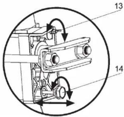
- Note! Unscrew the air screw (13) 3–4 revolutions, so that a noticeable air current can be felt during usage. Otherwise the seals in the hydraulic system may be damaged and make the log splitter unfit for use.
- Before use, ensure that the push rod nuts are fastened as the log splitter might be damaged otherwise.
Product markings and safety symbols on the machine


Warning! Risk of injury from moving parts. Beware. Keep hands away from moving parts during the entire cleaving process.
Warning! Risk of injury from moving parts when removing a jammed log. Do not remove it with your hands - use a tool.
Warning! Risk of injury from moving parts. Always be aware of how the pressure plate moves.
It is forbidden for anyone but the machine operator to be within the working area of the machine. Keep children, pets and unauthorized personnel out of the working area of the machine.
Switch off the machine and disconnect the plug from the socket when not using the machine, before cleaning and service.
Consider the environment, take care of waste oil according to local environment regulations.
Ensure that the machine is not damaged before use. Check again that the power cord is undamaged, if there are any loose screws/nuts and if the operating levers work well.
Read the manual!
Read the entire manual and try to understand the machine's work cycle.
Use safety goggles!
Protect your eyes against shooting wood chips. Use safety goggles or a visor.
Use gloves!
Use safety boots!
Use safety boots with steel toe caps which protect against falling objects.
Product description
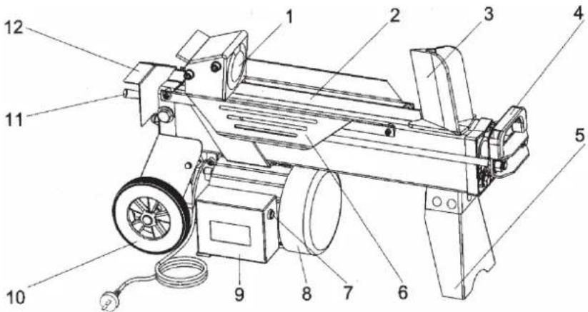
Components
- Pressure plate
- Cleaving table
- Cleaver
- Handle
- Brace
- Lateral supports
- Power switch
- Motor
- Electricity box
- Wheels for use when moving short distances
- Operating lever
- Safeguard for operating lever
- Bleeding screw
- Oil plug and dipstick
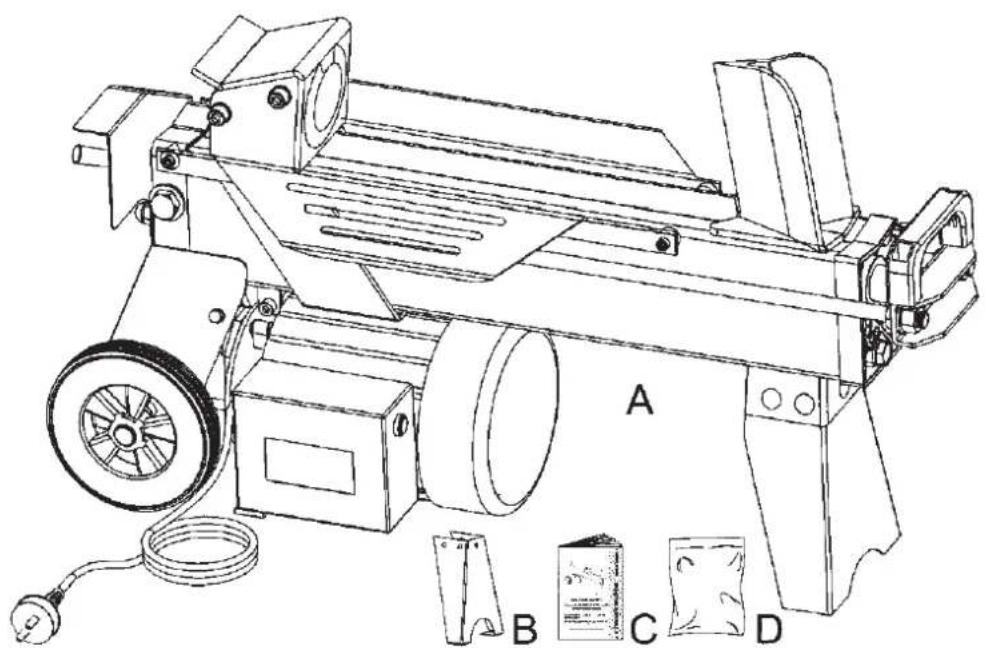
The package box contains
A. Log splitter
B. Brace
C. Manual
D. Brace
Assembly
Assemble the brace using the bolts enclosed.
natural_image
Technical line drawing of a mechanical device with labeled parts A, B, C, D (no text or symbols on the diagram itself)Preparation
- Place the log splitter on a flat and stable work surface at a practical height.
- Connect the power cable to a socket, preferably via an earth fault breaker. Remember to place the cable so that it will not damaged when working the log splitter.
- Unscrew the air screw (13) 3-4 revolutions, so that a noticeable air current can be felt during use.
Working with the log splitter
- Always place the side with the least amount of knots against the cleaver and always cleave along the grain.
- Place the log so that it is stable. Use the work bench lateral supports.
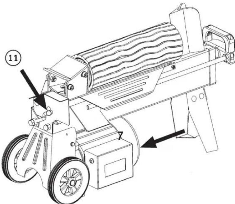
- Start the motor by pressing and then holding down the switch (7).
- Start the hydraulics: Push the operation lever (11) down (keeping the switch depressed)
- The pressure plate on the piston rod will now press the piece of wood against the cleaver.
- Release the operating lever and switch to complete the cleavage (when the log has been split).
Note! The pressure plate automatically stops approx. 12–14 cm from the cleaver.
natural_image
Technical line drawing of a mechanical device with rollers and wheels, showing motion arrows (no text or symbols)- Note! If cleaving does not start within 5 seconds in spite of full pressure: release the operating lever and switch and let the pressure plate retract. Then turn the log 90 degrees or turn it around and try again.
- Note! Close the air screw (13) during transport and when storing the machine as oil can seep out. When storing the machine with the air screw open for long periods of time, the oil absorbs moisture from the air which can lead to the hydraulic system rusting inside.
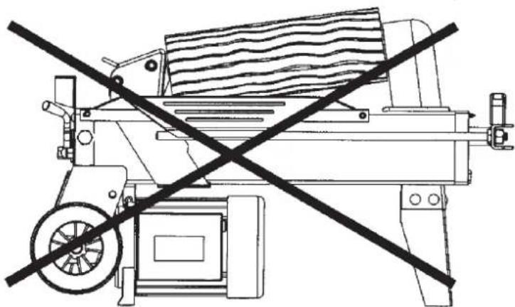
• Note! Do not cleave using only the upper part of the cleaver as the imbalance might damage the log splitter.
natural_image
Technical line drawing of a mechanical device with a diagonal black crossbar (no text or symbols)If the log jams
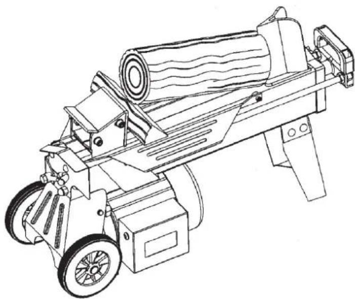
- Stop the cleaving.
- When the pressure plate has returned to its original position: place a wooden wedge under the jammed log.
- Start the log splitter and push the wedge in using the pressure plate.
- If necessary, repeat using a larger wedge.
natural_image
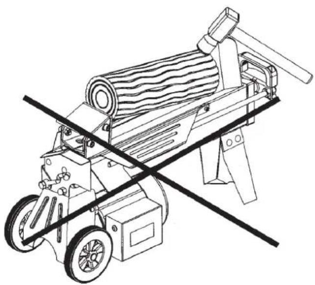
Line drawing of a mechanical device with cylindrical components and wheels (no text or symbols)Note! Never try to get a piece of wood out which is under pressure by chopping at it. It can splinter at high velocity which can lead to personal injury or damage to the log splitter.
natural_image
Line drawing of a manual machine with a cylindrical roller and two wheels, crossed by a diagonal line (no text or symbols)Maintenance
Changing the hydraulic oil
The hydraulic oil has to be changed at regular intervals (approx. 150 hrs) according to the following:
- Ensure that the pressure plate is in its original position and disconnect the power cord.
- Unscrew the oil plug.
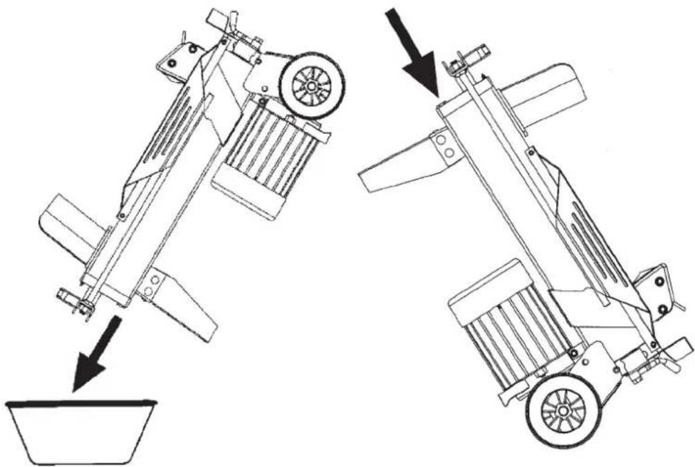
- Lift the pull handle and tip the log splitter over a collecting vessel which holds at least 4 litres and wait until all the oil has run out.
- Tip the log splitter so that the motor side is up and fill using good quality hydraulic oil (approx. 2.4 litres)
- Wipe the dipstick and place it in the tank when the log splitter is in a vertical position. Pull it back out and take a reading. The oil level should be between the two markings on the dipstick.
- Clean the oil plug and screw it back properly so that the oil does not leak out.
- Check the oil level regularly and when necessary, top it up.
natural_image
Technical line drawing of two mechanical devices with arrows indicating motion, no text or symbols presentKeep the cleaver sharp!
- Keep the cleaver sharp by regularly filing off the burrs of the cutting edge using a fine-toothed metal file.
Other Maintenance
• Always unplug the plug before servicing or making adjustments.
- Ensure that all power cables, plugs and switches are undamaged and in good working order.
- Clean all of the surfaces on the log splitter using a brush and dry cloths.
- Store the machine in a dry, clean and non-corrosive environment out of reach of children. Ensure that the storage temperature does not fall below -25^ C.
- Ensure that all screws and nuts are fastened, especially the drawbar nuts (beside the handle).
Protect the environment
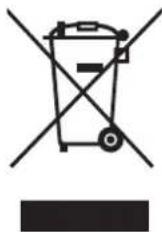
Sort your waste and recycle products instead of throwing them away. All machines, hoses and packing material should be sorted and handled according to local environmental regulations.
Troubleshooting
| Problem Possible cause | Suitable measure | |
| The machine failed to cleave the piece of wood. | The log is wrongly placed. Turn around or rotate the log. | |
| The hardness or diameter of the log is too great. | Try decreasing the diameter or length before cleaving. | |
| The cleaver is blunt or damaged. Sharpen the cleaver (see Maintenance). | ||
| Oil leakage. Find the leakage and let a qualified technician repair it. Top up the oil. | ||
| Pressure regulator wrongly adjusted. Let a qualified technician with access to testing equipment repair it. | ||
| The pressure plate moves abruptly with a jarring sound and strong vibrations. | Oil pressure too low - air in the system. | Check the level and if required top up the oil or repair leakage. |
| Oil leakage around the piston or other component. | Air pockets in the hydraulic system during operation. | Loosen the bleeding screw 3–4 revolutions before starting operation. |
| The air screw has not been tightened before transport. | Tighten the bleeding screw before transport. | |
| The oil plug is not tightened sufficiently. | Tighten the oil plug. | |
| The hydraulic valve and/or packing are worn out. | Contact retailer. | |
Technical specification
Model WS4T-37
Motor 230 V AC 50Hz
Effect 1500 W
Enclosure class IP54
Cleaving capacity* ∅ 5–25 cm, length 37 cm
Recommended working temperature +5°C to +40°C
Cleaving force 4 tonnes
Hydraulic pressure 16 Mpa
Amount of hydraulic oil 2.4 litres
Dimensions Length 770 mm
Width 250 mm
Height 460 mm
Weight 37 kg
*The stated values are for guidance. The capacity depends on the hardness of the piece of wood, diameter and the amount of knots.
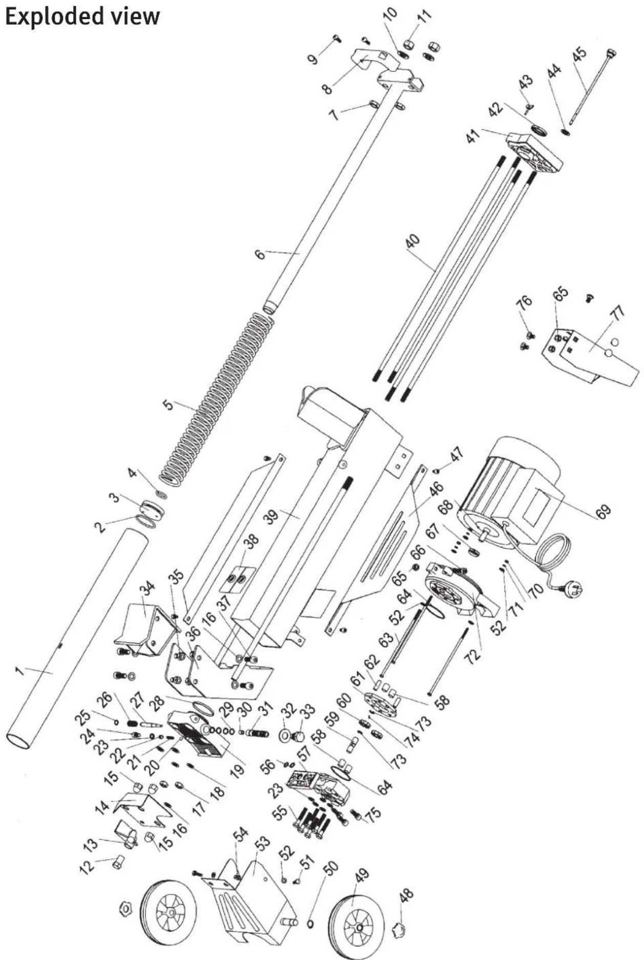
| Number Name Amount | ||
| 1 Cylinder 1 | ||
| 2 O-ring gasket 1 | ||
| 3 Piston 1 | ||
| 4 O-ring gasket (inner) 1 | ||
| 5 Spring (5.5-47-667) 1 | ||
| 6 Piston rod 1 | ||
| 7 Nut, M14 2 | ||
| 8 Handle 1 | ||
| 9 Bolt M6-15 2 | ||
| 10 Gasket, 14 mm 2 | ||
| 11 Nut, M14 2 | ||
| 12 Operating lever 1 | ||
| 13 Operating lever 1 | ||
| 14 Operating lever 1 | ||
| 15 Domed cap nut 3 | ||
| 16 Gasket 2 | ||
| 17 Nut M10 | 2 | |
| 18 Gasket 4 | ||
| 19 Side, (left) 1 | ||
| 20 Steel ball 6 mm 1 | ||
| 21 Spring | 1 | |
| 22 | Adjusting screw for pressure limiter, m8-10 | 1 |
| 23 Copper packing 9 - 12 | 1 | |
| 24 Cover screw | 1 | |
| 25 Locking ring for valve piston | 1 | |
| 26 Spring | 1 | |
| 27 Valve piston | 1 | |
| 28 Cylinder sealing, 55-3 | 1 | |
| 29 O-ring gasket for valve 10.6-1.8 | 4 | |
| 30 Valve sensor | 1 | |
| 31 Valve cylinder | 1 | |
| 32 Copper packing 16-32 | 1 | |
| 33 Plug | 1 | |
| 34 Pressure plate | 1 | |
| 35 Nut, M10 4 | ||
| 36 Pull bracket | 1 | |
| 37 Bolt, M10-25 | 4 | |
| 38 Friction plate | 2 | |
| 39 Stand/Oil tank | 1 | |
| 40 Stud bolt | 4 | |
| 41 Side (right) | 1 | |
| 42 Piston rod sealing | 1 | |
| 43 Air screw | 1 | |
| 44 Packing | 1 | |
| 45 Dipstick | 1 | |
| 46 Lateral supports | 2 | |
| 47 Bolt, M6-10 | 4 | |
| 48 Centre cover | 2 | |
| 49 Wheel 2 | ||
| 50 Locking ring for wheels | 2 | |
| 51 Bolt M6-20 2 | ||
| 52 Gasket 2 | ||
| 53 Wheel bracket | 1 | |
| 54 Nut, M6 2 | ||
| 55 Bolt, M8-45 | 6 | |
| 56 O-ring gasket, inner diameter 10.6 mm | 2 | |
| 57 Hydraulic pump side | 1 | |
| 58 Slide bearing | 2 | |
| 59 Axel | 1 | |
| 60 Pump wheel | 2 | |
| 61 Pump house | 1 | |
| 62 Pin | 2 | |
| 63 Bolt, M5-185 | 3 | |
| 64 O-ring gasket pump house | 2 | |
| 65 Nut M8 | 1 | |
| 66 Bolt, M8-35 | 1 | |
| 67 Sealing for motor axel | 1 | |
| 68 Feather key | 1 | |
| 69 Motor | 1 | |
| 70 Gasket 3 | ||
| 71 Spring washer | 3 | |
| 72 Side motor/pump | 1 | |
| 73 Locking ring for drive shaft | 2 | |
| 74 Steel ball, diameter 2.5 mm | 2 | |
| 75 Bolt, M8-20 | 3 | |
| 76 Bolt, M8-10 | 5 | |
| 77 Brace | 1 | |
Vedklyv
ART.NR. 18-3038 MODELL WS4T-37-UK
30-9285
WS4T-37
natural_image
Technical line drawing of a mechanical device with labeled parts A, B, C, D (no text or symbols on the diagram itself)Förberedelser
natural_image
Technical line drawing of a mechanical device with no visible text or symbolsnatural_image
Line drawing of a mechanical device with a diagonal line crossing through it, no text or symbols present.natural_image
Line drawing of a mechanical device with wheels and a cylindrical component (no text or symbols)natural_image
Line drawing of a mechanical device with a cylindrical roller and two wheels, intersected by a diagonal line (no text or symbols)Underhåll
Byte av hydraulolja
natural_image
Technical line drawing of two mechanical devices with arrows indicating motion, no text or symbols presentnatural_image
Technical line drawing of a lathe machine with labeled components A, B, C, D (no text or symbols on the machine itself)Forberedelser
natural_image
Technical line drawing of a mechanical device with a diagonal black crossbar (no text or symbols)natural_image
Line drawing of a mechanical device with cylindrical components and wheels (no text or symbols)natural_image
Line drawing of a mechanical device with a roller and two crossed lines (no text or symbols)Vedlikehold
natural_image
Technical line drawing of two mechanical devices with arrows indicating motion, no text or symbols present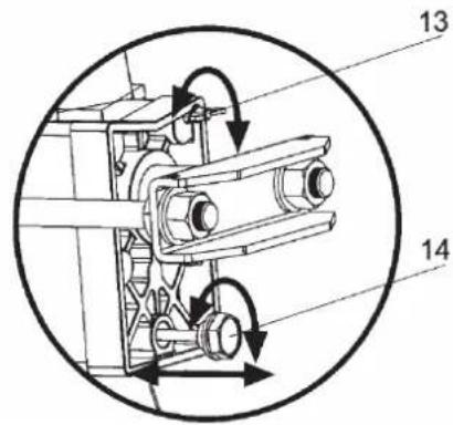
Pakkauksen sisältö
natural_image
Technical line drawing of a mechanical device with labeled parts A, B, C, D (no text or symbols on the diagram itself)Esivalmistelut
natural_image
Technical line drawing of a mechanical device with no visible text or symbolsnatural_image
Technical line drawing of a mechanical device with a diagonal black crossbar crossing it, no text or symbols present.Rangan jumittuessa
natural_image
Line drawing of a mechanical device with cylindrical components and wheels (no text or symbols)Huom.!
natural_image
Line drawing of a mechanical device with a roller being cut, intersected by a diagonal line (no text or symbols)Huolto
natural_image
Technical line drawing of two mechanical devices with arrows indicating assembly or motion, no text or symbols present.Pidä terä terävänä
natural_image
Symbol of a trash bin crossed with a diagonal line and a horizontal bar below (no text or labels)Vianetsintä
Lieferumfang
natural_image
Technical line drawing of a mechanical device with labeled parts A, B, C, D (no text or symbols beyond labels)Vorbereitungen
natural_image
Technical line drawing of a mechanical device with no visible text or symbolsnatural_image
Line drawing of a machine with a diagonal line crossing through it, no text or symbols presentnatural_image
Line drawing of a mechanical device with wheels and a cylindrical component (no text or symbols)natural_image
Line drawing of a mechanical device with a cylindrical roller and two wheels, intersected by a diagonal line (no text or symbols)Wartung
natural_image
Technical line drawing of two mechanical devices with arrows indicating motion, no text or symbols presentDeclaration of Conformity
Klas Balkow President
Insjön, Sweden, 2013-10-31
SVERIGE
KUNDTJÄNST
Tel:
0247/445 00
Fax:
0247/445 09
E-post: kundservice@clasohlson.se
INTERNET
www.clasohlson.se
BREV Clas Ohlson AB, 793 85 INSJÖN
NORGE
KUNDESENTER
Tlf.:
23 21 40 00
Faks:
23 21 40 80
E-post: kundesenter@clasohlson.no
INTERNETT
www.clasohlson.no
POST
Clas Ohlson AS, Postboks 485 Sentrum, 0105 OSLO
SUOMI
ASIAKASPALVELU
Puh.: 020 111 2222
10 – 13 Market Place
Kingston Upon Thames
Surrey
KT1 1|Z
DEUTSCHLAND
KUNDENSERVICE
- Hydraulic Log Splitter
- General safety rules
- Keep the tools in working order.
- Switch the power off.
- Remove all spanners and service tools.
- Avoid starting unintentionally.
- Use the correct extension cables.
- Use common sense and be careful.
- Ensure that all parts are intact.
- Use recommended fittings.
- Must be repaired by a qualified technician.
- Electrical tools should be connected to the mains via an earth fault breaker for personal safety.
- Special safety regulations for log splitters
- Product markings and safety symbols on the machine
- Product description
- Components
- The package box contains
- Assembly
- Preparation
- Working with the log splitter
- If the log jams
- Maintenance
- Changing the hydraulic oil
- Keep the cleaver sharp!
- Other Maintenance
- Protect the environment
- Technical specification
- Vedklyv
- Förberedelser
- Underhåll
- Byte av hydraulolja
- Forberedelser
- Vedlikehold
- Pakkauksen sisältö
- Esivalmistelut
- Rangan jumittuessa
- Huom.!
- Huolto
- Pidä terä terävänä
- Lieferumfang
- Vorbereitungen
- Wartung
- Declaration of Conformity
- SVERIGE
- NORGE
- SUOMI
- DEUTSCHLAND
Brand : Cotech
Model : WS4T-37
Category : Log splitter