ZI-BRM35 - Lawn mower Zipper - Free user manual and instructions
Find the device manual for free ZI-BRM35 Zipper in PDF.

| Product Type | Gasoline Lawn Mower |
| Brand | Zipper |
| Model | ZI-BRM35 |
| Engine Type | 1-Cylinder 4-Stroke OHV Engine |
| Displacement | 123 cc |
| Power | 2.6 kW |
| Fuel Type | Unleaded Gasoline |
| Fuel Tank Capacity | 1.0 Litre |
| Oil Capacity | 0.6 Litre |
| Oil Type | SF 15W40 |
| Cutting Width | 400 mm |
| Cutting Height Range | 20 – 60 mm (8 positions) |
| Blade Speed | 2850 min⁻¹ |
| Self-Propelled | Yes (rear wheel drive, ~3.0 km/h) |
| Grass Catcher | Yes, rear discharge |
| Mulching Function | Yes (with mulch plug) |
| Side Discharge | No (only on ZI-BRM56/60) |
| Sound Pressure Level | 90 dB(A) |
| Sound Power Level | 96 dB(A) |
| Safety Features | Engine brake handle, safety guard, blade stop |
| Warranty | 2 years for amateur use |
Frequently Asked Questions - ZI-BRM35 Zipper
User questions about ZI-BRM35 Zipper
0 question about this device. Answer the ones you know or ask your own.
Ask a new question about this device
Download the instructions for your Lawn mower in PDF format for free! Find your manual ZI-BRM35 - Zipper and take your electronic device back in hand. On this page are published all the documents necessary for the use of your device. ZI-BRM35 by Zipper.
USER MANUAL ZI-BRM35 Zipper
natural_image
Three green LiDPEM lawn mower machines with visible branding and mounting brackets (no text or symbols on the motors themselves)ZI-BRM35 / ZI-BRM56 / ZI-BRM60
EAN : 9120039230191 / 9120039230801 / 9120039230214
DE
Read the operation manual care-fully before first use.

ATTENTION: Check Oil (SF 15W40)!
SL
12.1 Residual Risks.... 28
13 ASSEMBLY 28
13.1 Scope of delivery.... 28
13.2 Mounting the guide bar 29
13.3 Draw-in starter handle rope guide 29
13.4 Assembly of the grass catcher 30
13.5 Assembly grass catcher ZI-BRM56.... 30
13.5.1 Remove the mulch wedge: 31
13.5.2 Attaching the grass catcher 32
13.5.3 Install storage console 32
13.6 Refuelling.... 32
13.7 Fill with oil 33
13.8 Operating Company 33
14 OPERATION
14.1 Engine Start / Stop 34
14.2 Height adjustment 34
14.3 Self-driving function / auto-wheel drive.... 35
14.4 Grass catcher 35
14.5 ZI-RBM 56 / ZI-BRM 60 35
14.5.1 Conversion to a mulching mower 35
14.5.2 Change to the mower with side discharge 35
15 MAINTENANCE
36
15.1 Check the oil level 37
15.2 Maintenance of the air filter 37
15.3 Damaged blades 37
15.4 Change the blade 37
15.5 Sharpen knives 38
16 TROUBLESHOOTING 38
17 UVOD 39
18 TEHNIKA 40
EN ATTENTION! Ignoring the safety signs and warnings applied on the machine as well as ignoring the security and operating instructions can cause serious injuries and even lead to death.
EN READ THE MANUAL! Read the user and maintenance manual carefully and get familiar with the controls n order to use the machine correctly and to avoid injuries and machine defects.
natural_image
Simple line drawing of a boat with a handle and water droplet, no text or symbols present.EN ATTENTION! For transport oil has been drained. Fill up with 4-stroke quality motor oil before first operation! Failure to do so will result in permanent engine damage and void guarantee.
EN CE-Conformal! - This product complies with the EC-directives.
natural_image
Close-up of a green industrial component with three bolts and bolts, labeled 'Bild 1' (no other text or symbols visible)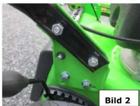
natural_image
Close-up of a green tractor's front wheel and black metal bracket with bolts (no visible text or symbols)natural_image
Close-up of a bicycle's side panel with metal clip and attached bracket, labeled 'Bild 3' (no other text or symbols)
natural_image
Close-up of a bicycle seatbelt with black handle and metal frame, labeled 'Bild 4' (no other text or symbols)natural_image
Close-up of a black mechanical component with attached clamps, placed on a textured surface (no visible text or symbols)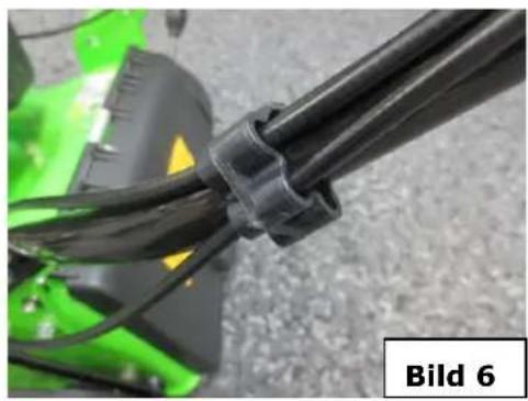
natural_image
Close-up of a black plastic tool with green base and yellow warning label, no readable text or symbols on the tool itself.natural_image
Close-up of a person using a screwdriver to apply material to a component, labeled 'Bild 7' (no other text or symbols visible)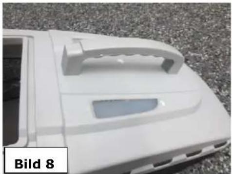
natural_image
White plastic car body with a handle and side panel, labeled 'Bild 8' (no other text or symbols visible)natural_image
Close-up of a blue industrial component with visible bolts and a black handle, labeled 'Bild 9' in the corner (no other text or symbols)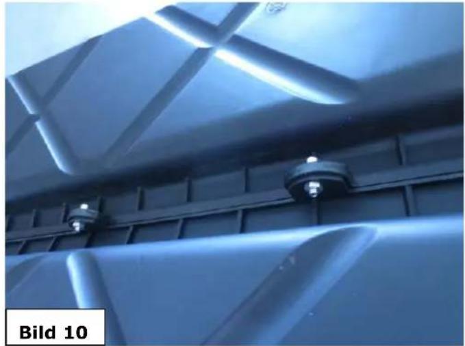
natural_image
Close-up of a metallic structural panel with blue lighting and mounting fixtures (no text or symbols visible)natural_image
Close-up of a mechanical component with grid-patterned ventilation grille and mounting brackets (no text or symbols visible)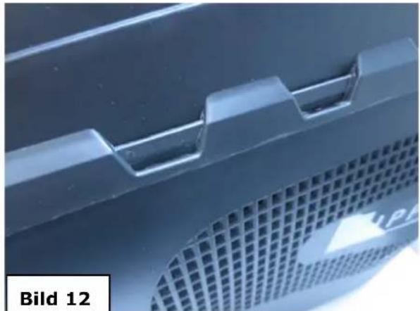
natural_image
Close-up of a metallic component with grid pattern and textured surface (no text or symbols visible)natural_image
Close-up of a blue plastic container with a handle and ventilation slots, labeled Bild 13 (no text or symbols on the main subject)natural_image
Green industrial robotic brush with a rectangular vent, mounted on wheels (no visible text or symbols)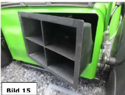
natural_image
Green industrial vehicle front panel with black plastic housing, no visible text or symbols on the main subjectnatural_image
Close-up of a green industrial machine component with visible mechanical parts and a black cable, labeled 'Bild 16' (no readable text or symbols on the main subject)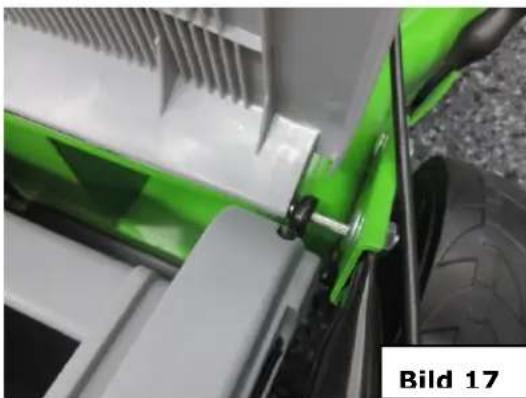
natural_image
Close-up of a green and white mechanical component with clamps, no visible text or symbolsnatural_image
Green 3D-printed object labeled 'ZIPPER' with a circular opening, mounted on a stand (no text or symbols on the object itself)6.6 Tanken
natural_image
Close-up of a hand inserting a black plastic component into a green industrial machine component (no visible text or symbols)
HINWEI S
natural_image
Close-up of a green lawn mower with a water bottle inserted, no visible text or symbols on the device itself.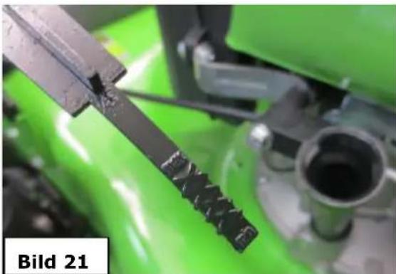
natural_image
Close-up of a mechanical tool with a serrated edge, set against a green background (no text or symbols visible)natural_image
Close-up of a hand holding a black mechanical device with a handle, labeled 'Bild 23' in the corner (no other text or symbols visible)natural_image
Close-up of a green motorcycle with visible tire and mechanical components, no text or symbols presentnatural_image
Close-up of a hand holding a black cylindrical object, labeled 'Bild 25' in the corner (no other text or symbols visible)natural_image
Close-up of a green and black plastic car bumper with a metallic screw attachment (no text or symbols visible)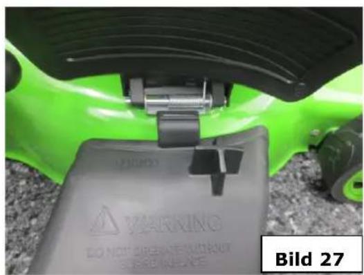
natural_image
Close-up of a green and black mechanical component with a warning label, no readable text or symbols in the main image area.natural_image
Close-up of a gray plastic device with a logo, placed on a textured surface next to a green safety helmet (no visible text or symbols)Was ist mulchen?
natural_image
Illustration of mechanical components and tools, including a tool holder, fan blade, gear shift, and cutting tool (no text or symbols)natural_image
Technical line drawing of a mechanical component with multiple parts and a labeled section 'Bild 29' (no other text or symbols)9 FEHLERBEHEBUNG
This manual contains Information and important instructions for the installation and correct use of the Gasoline lawn mower ZI-BRM35 / ZI-BRM56 / ZI-BRM60. This manual is part of the machine and shall not be stored separately from the machine. Save it for later reference and if you let other persons use the machine, add this instruction manual to the machine.

Please read and obey the security instructions!
Before first use read this manual carefully. It eases the correct use of the machine and prevents misunderstanding and damages of machine and the user's health.
Due to constant advancements in product design construction pictures and content may diverse slightly. However, if you discover any errors, inform us please.
Technical specifications are subject to changes!
Please check the product contents immediately after receipt for any eventual transport damage or missing parts. Claims from transport damage or missing parts must be placed immediately after initial machine receipt and unpacking before putting the machine into operation. Please understand that later claims cannot be accepted anymore.
Copyright
© 2015
This document is protected by international copyright law. Any unauthorized duplication, translation or use of pictures, illustrations or text of this manual will be pursued by law – court of jurisdiction is Linz, Austria!
CUSTOMER SERVICE CONTACT
| ZI-BRM35/56 | |
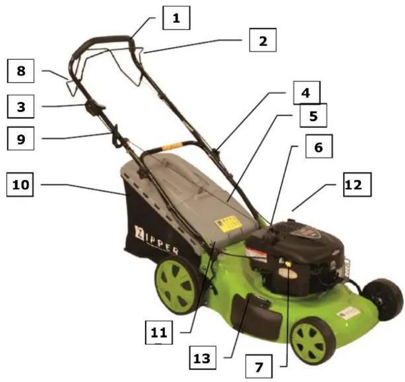
| 1 | Handlebar |
| 2 | Engine brake handle |
| 3 | Trigger throttle |
| 4 | Holm gland |
| 5 | Ejection shield |
| 6 | gasoline tank |
| 7 | air filter |
| 8 | Wheel control lever |
| 9 | Pull-starter grip |
| 10 | Grass catcher |
| 11 | Height adjustment lever |
| 12 | Oil filler neck |
| ZI-BRM60 | |
| 1 | Handlebar |
| 2 | Engine brake handle |
| 3 | Trigger throttle |
| 4 | Holm gland |
| 5 | Ejection shield |
| 6 | gasoline tank |
| 7 | air filter |
| 8 | Wheel control lever |
| 9 | Pull-starter grip |
| 10 | Grass catcher |
| 11 | Height adjustment lever |
| 12 | Oil filler neck |
| 13 | Side discharge damper |
11.2 Technical data
| ZI-BRM35 | ZI-BRM56 | ZI-BRM60 | |
| Engine-Type | 1 Cyl. 4-stroke-OHV engine | 1 Cyl. 4-stroke-OHV engine | 1 Cyl. 4-stroke-OHV engine |
| Fuel type | Lead-free-gasoline | Lead-free-gasoline | Lead-free-gasoline |
| Gasoline tank capacity | 1,0 Liter | 1,2 Liter | 1,5 Liter |
| Power | 2,6 kW / 123 ccm | 3,5 kW / 173 ccm | 2,5 kW / 190 ccm |
| Oil tank capacity | 0,6 Liter | 0,65 Liter | 0,65 Liter |
| Speed | 2850 min ^-1 | 2750 min ^-1 | 2750 min ^-1 |
| Cutting width / height mm | 400 / 20 – 60 | 560 / 30 – 85 | 510 / 30 – 80 |
| Engine oil | SF 15W40 | SF 15W40 | SF 15W40 |
| Sound pressure level LPA | 90 db(A) | 90 db(A) | 96 db(A) |
| Sound power level LWA | 96 dB(A) | 98 dB(A) | 98 dB(A) |
12 SAFETY
The ZIPPER lawnmower ZI-BRM35/56/60 may exclusively for mowing lawn / grass to walk safely grounds.


ATTENT ION
Before each operation, the oil level must be checked! If necessary, add engine oil to lower edge of filler neck.

Unauthorized modifications and manipulations of the machine immediately invalidate all warranty and damage claims.

Operating the machine only when sufficient light, after dusk, you should not work any more. With fatigue, lack of concentration or under the influence of drugs, alcohol or drugs is prohibited to work with the machine

During refueling the fire, naked flame and smoking prohibited. Refuel with the engine running or when engine parts are still hot is strictest prohibited. Refuel only outdoors or in well-ventilated areas.

Wipe off spilled fuel immediately. Fuel is highly flammable!

The machine may only be operated by qualified personnel enrolled. Third persons, especially children, and people are not trained to think of the work environment away!

Risk of burns! During the operation flow of hot exhaust gases and engine parts such as the carburetor and engine become hot.

Danger of suffocation! The engine produces poisonous gases during operation. These gases may be odorless and invisible. Never run the engine in closed or poorly ventilated areas

Work attentively, safety conscious and always make sure that a safe STAND when working!
Particular caution should be exercised when changing direction!
Working in the rain / snow and other slippery surfaces is prohibited.
Slipping / tripping / falling are a major cause of serious injury or death.
Watch out for uneven or slippery work surfaces.

The machine may only be operated outdoors.
The machine may only be stored if all components are completely cooled!
Terms of Service.
This machine is designed for cutting grass solely to use real (not artificial turf). Never use the mower for any other purpose. Any other use may mean danger for your safety and cause damage to the mower.
People under 16 years and those who are not familiar with the operating instructions should not use the mower.
The user is responsible for the safety of others in the work area. Keep children and pets at a safe distance while the mower is in operation.
Before mowing, remove any debris from the lawn which could be thrown from the machine you still pay attention to any debris did may have overlooked
12.1 Residual Risks
Danger of noise:
Working without ear protection can cause hearing damage over time.
Danger from the working environment:
Watch out for stones and other obstacles.
Risk to the hands or fingers:
Grab while it is working in the mowing apparatus. Severe cuts or risk of injury or death!
Risk of injury by capture of cords, wires or clothing as de-projecting legs or laces through the blades!
Working environment for foreign objects scan. Pants stuck in safety shoes. No loose laces!
Burns on contact with hot engine components, especially the exhaust
Health impairment through Vibrations: Prolonged exposure to the engine can lead to joint damage despite the vibration damping of the management Holmes. Wear protective gloves and vibration-place regular operation breaks.
Risk of injury from thrown stones or soil during the mowing operation. Keep other people away from the work environment and apply the prescribed protective equipment.
Electric shock: with the engine running can cause electric shock when touching the ignition plug.
Through compliance with all safety regulations such hazards can be reduced to a minimum!
13 ASSEMBLY
13.1 Scope of delivery
Unpack the lawnmower ZIPPER ZI-BRM 35/56/60 and check the machine is in perfect condition and the delivery is complete.
Package Contents:
ZI-BRM35:
1x lawnmower with demounted guide rail, 1x grass catcher with 1x holder, instruction sheet, 1x socket wrench for spark plug with pin 8x120mm, 2x plastic eyelets
ZI-BRM56:
as above, plus: grass catcher consisting of 3 parts and screws, 1x handle for grass catcher bodice, 4 mounting screws f. Handle, 1x side off draft guidance, 1x mulching, 1x storage console
ZI-BRM60:
as above, plus: 1x handle for grass catcher, 4 mounting screws for handle, 1x side discharge guide, 1x mulching.
Note: When setting up and folding the handlebar is particularly important to pay attention to kink-free course of the Bowden cables.
13.2 Mounting the guide bar
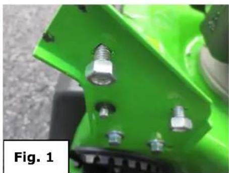
Remove the protective film from the guide rail. Deflected tighten with 2 Star knobs on both sides On the chassis on both sides remove the 2 nuts preassembled with 2 screws. (fig. 1)
natural_image
Close-up of a green mechanical component with four bolts and screws (no visible text or symbols)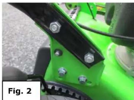
natural_image
Close-up of a green industrial machine component with bolts and mounting brackets (no visible text or symbols)Guide rail and fix the lower part with two screws on both sides (fig. 2) on the chassis of the mower
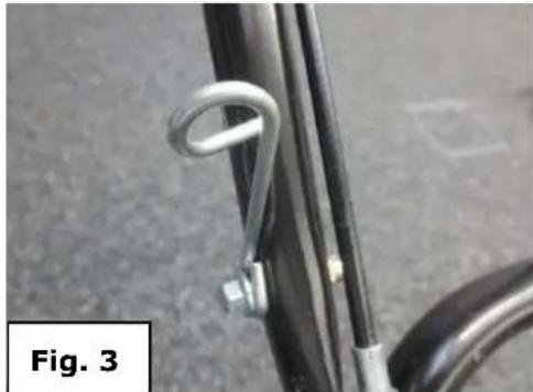
13.3 Draw-in starter handle rope guide
Loosen the motor brake by pressing the engine brake handle (2) to the spar. Attach the pull-starter grip to the top of the spar-provided cable guide (fig. 4/5).
natural_image
Close-up of a bicycle wheel handle and metal bracket, labeled 'Fig. 3' (no other text or symbols)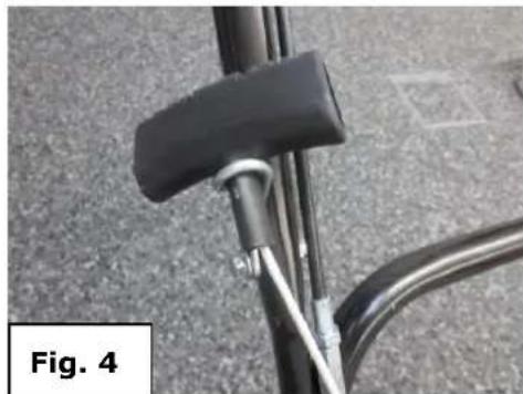
natural_image
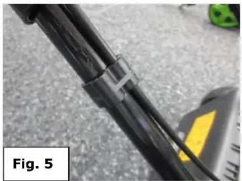
Close-up of a bicycle's side panel and handle, labeled 'Fig. 4' (no other text or symbols visible)Secure the Cables with 2 plastic rings, left and bottom right of the guide rail. (fig. 5/6)
natural_image
Close-up of a black mechanical component with attached clamps, placed on a paved surface (no visible text or symbols)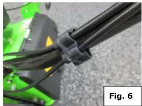
natural_image
Close-up of black plastic cable with yellow highlights, partially covered by green machinery (no text or symbols visible)13.4 Assembly of the grass catcher
Mounting handle only ZI BRM56 and ZI BRM60
natural_image
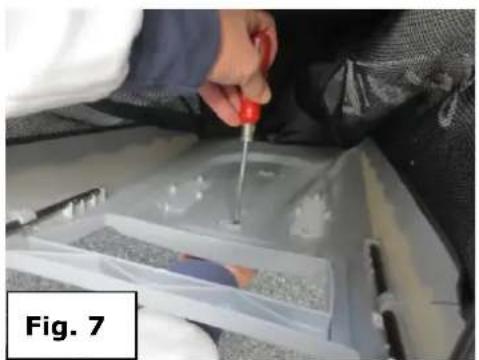
Close-up of a hand using a screwdriver to apply material to a component, labeled 'Fig. 7' (no other text or symbols visible)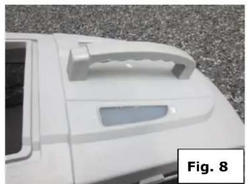
natural_image
White plastic car body with a handle and side panel, placed on gravel surface (no text or symbols visible)Grip on grass catcher with 4 screws on the inside (fig. 7) of the grass catcher with star screw-driver screw (fig. 8)
13.5 Assembly grass catcher ZI-BRM56
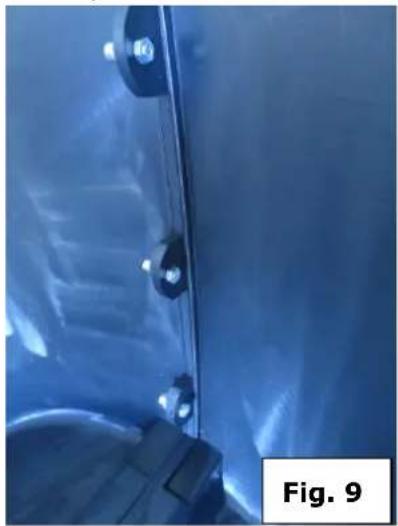
The 2 pan halves with 3 screws inside screw together as shown in fig. 9.
natural_image
Close-up of a blue industrial component with visible bolts and a labeled section 'Fig. 9' (no readable text or symbols on the main subject)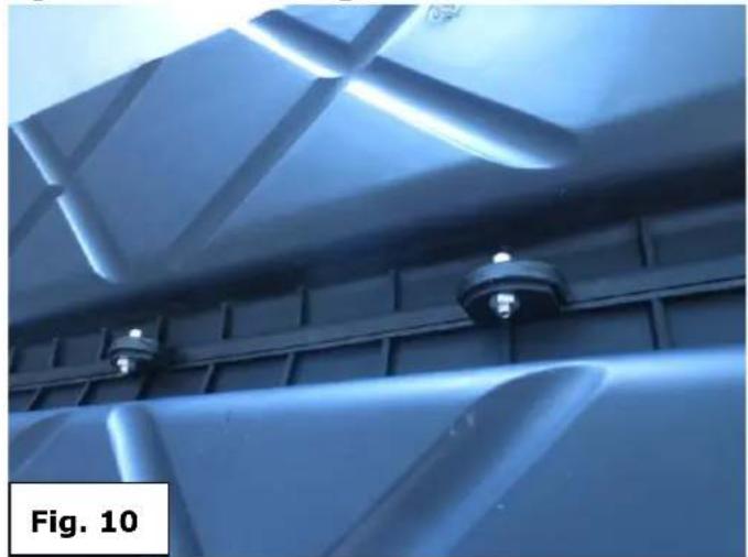
natural_image
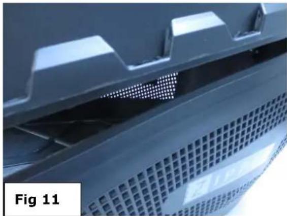
Close-up of a metallic structural panel with recessed ceiling and mounting fixtures (no text or symbols visible)When the halves with 3 screws below the outside as shown in fig. 10 Bolt together.
Handle the grass catcher cover with 4 screws on the inside (Fig. 7) of the grass catcher with star screwdriver screw (Fig. 8)
Put lid on grass catcher pan and all around good push in terminal block (Fig. 9).
natural_image
Close-up of a mechanical component with grid-patterned surfaces and a perforated base (no visible text or symbols)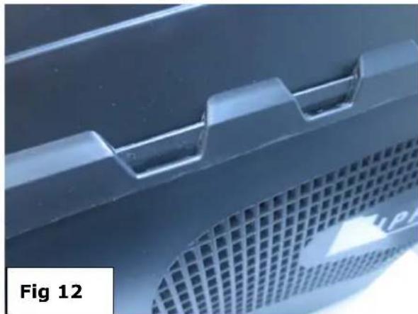
natural_image
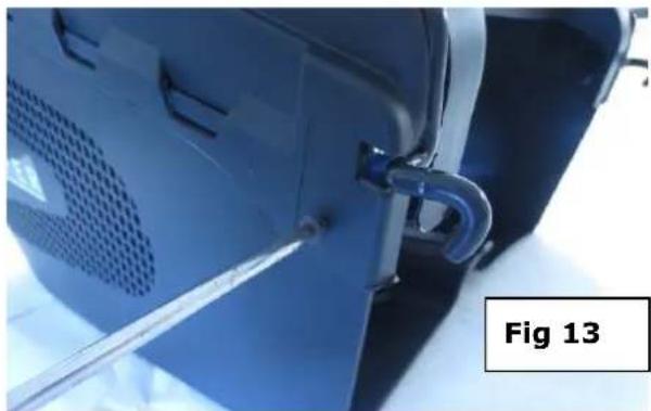
Close-up of a blue plastic component with grid pattern and textured surface (no text or symbols)Cover with grass catcher tray screw holes at the sides. (Fig. 13)
natural_image
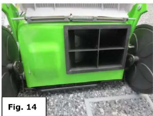
Close-up of a blue plastic container with a metal clip attached, labeled 'Fig 13' (no other text or symbols visible)13.5.1 Remove the mulch wedge:
Note: Carry out only with the engine stopped and complete stop the cutter!
Lift the rear discharge door (Fig. 14) and remove the mulching by releasing him at the notch and remove. (Fig. 15)
natural_image
Green industrial robotic device with black frame and wheels, labeled Fig. 14 (no text on device itself)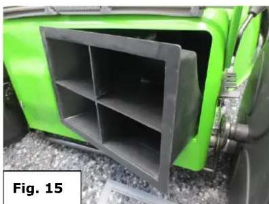
natural_image
Green tractor front view showing a black plastic enclosure with four compartments (no text or symbols visible)13.5.2 Attaching the grass catcher
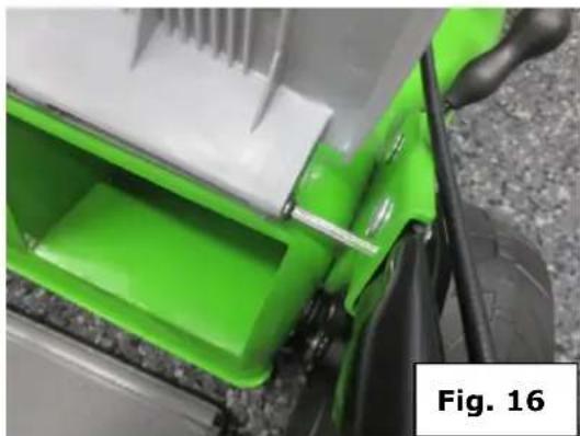
Pulling up the grass cover (fig. 16) and attaching the grass catcher on both sides by lateral suspension on grass protection cover on round bar. (fig. 17)
natural_image
Close-up of a green and black robotic vehicle with visible mechanical components and a white panel, labeled 'Fig. 16' (no text on the vehicle itself)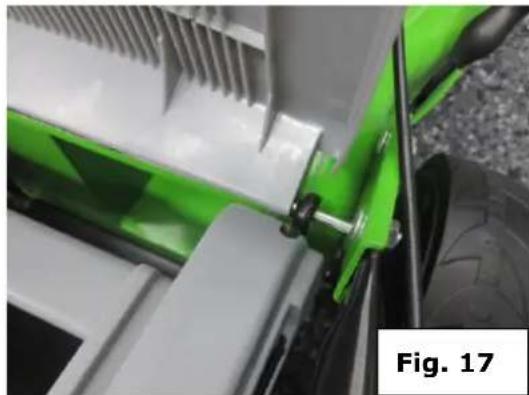
natural_image
Close-up of a green and white toy car with attached clamps, showing mechanical components (no visible text or symbols)13.5.3 Install storage console
- only for ZI-BRM56-
The storage console by pressing the 4 clamps on each fork mount. (Fig. 18)
And fix with the screws.

natural_image
Green 3D-printed device labeled 'ZIPPER' with a black handle and circular port, displayed against a white background (no readable text or symbols on the device itself)13.6 Refuelling
Important: Environmentally friendly unleaded gasoline can be used safely.
- Refuel only the recommended fuel grades.
- Allow to cool before refueling machine.
- Clean area around filler cap well, unscrew the fuel filler cap and fill to bottom of filler neck.
- Oil filler cap back on tight screws. (fig. 19)
Note: Fuel may contain substances similar to solvents.
- Avoid skin and eye contact with petroleum products.
- Wear gloves while refueling.
- Do not inhale fuel vapors.
- Keep fuel away from children

natural_image
Close-up of a hand adjusting a black plastic component on a green surface, with no visible text or symbols.13.7 Fill with oil
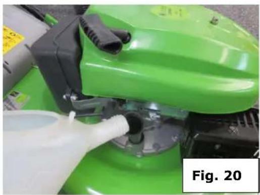
Fill the oil (SF 15W40) 0.6 L in the oil tank.(fig. 20)
Between measure used by the dipstick -without tighten up- between the upper max and lower min mark (fig. 21). Caution: Do not overfill
natural_image
Close-up of a green agricultural machine with a white plastic bottle inserted, labeled 'Fig. 20' (no readable text or symbols on the device itself)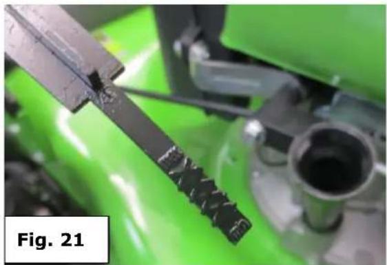
natural_image
Close-up of a mechanical component with green background, showing a black tool and textured surface (no visible text or symbols)The engine is delivered without oil: Fill in 0.6 liter oil before starting the engine!


ATTENT ION
ANY FINAL JAM NUT AND BOLT ON ANY DEAD TIGHT! WHILE OPERATING THE VIBRATING MACHINE STRONG, NOT TIGHTEN THE SCREWS CAN BREAK OFF AND LOST AND DANGEROUS SITUATION TO BE CARRIED!
13.8 Operating Company
SAFETY MEASURES
- Mower should be started only with correctly mounted grass catcher or side discharge.
- Switch off the engine before adjusting the cutting height or before you empty the grass collection container.
- Bring your hands or feet under the mower never or below the grass discharge chute.
- Remove before you start mowing, ask all foreign objects from the work area, which can be thrown from, the device. Figure F
- Make sure that children, bystanders and pets always keep a safe distance to the appliance while in operation.
- Raise your lawn mower to never, while you start the engine.


AC HTUN G
All work with the engine stopped and a complete stop of Cutter and removed spark plugs perform!
14 OPERATION
14.1 Engine Start / Stop
Start the engine, if you have your mower mounted correctly:
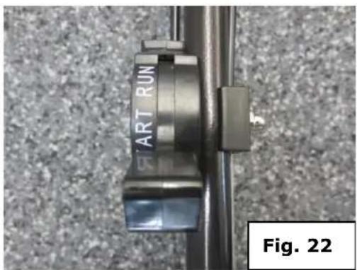
Move the Gas-lever to the START position. (fig. 22)
natural_image
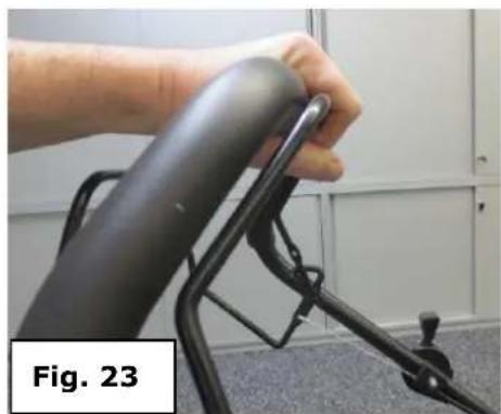
Close-up of a hand holding a black ergonomic device with a handle, labeled 'Fig. 23' (no other text or symbols visible)Pull the engine brake handle (2) against the handle (fig. 22). Pull the pull-start handle (9) until resistance is felt and then pull out quickly by.
Run the pull-starter handle slowly to the rope guide back as soon as the engine starts.
Set Lever to the engine running to RUN (fig. 22)
Let the engine brake handle (2) going to stop the engine and blade

WARNING! Keep hands and feet away from rotating parts.
14.2 Height adjustment

CAUTION: Do they at no time changes to the adjustment of the machine without shutting off the engine before.
Your mower is equipped with a central height adjustment which 8 different height settings from 20 - 60 mm offers.
Turn off the engine and wait before changing the cutting height to the rotating parts are no longer rotate.
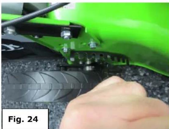
To change the cutting height, push the joystick in the direction of the wheel. Turn to the left to reduce the cutting height, turn clockwise increases the cut height (fig. 24). All wheels will be at the same height of the cut.
Note: The cutting height can be chosen so that the blade on uneven surfaces do not touch the ground! Mowing to low cutting adjustment should be performed only on a level, and plan lawns.
natural_image
Close-up of a green electric scooter's wheel assembly with a hand pressing the tread (no visible text or symbols)14.3 Self-driving function / auto-wheel drive
Press the wheel drive control lever (8) to the guide rail (fig. 40) and the mower will move automatically with the engine running at about 3.0 km/h forward.
Let the wheel drive control lever to release the mower no longer automatically moves forward.

natural_image
Close-up of a hand holding a black cylindrical device with metal brackets, indoors near a white cabinet (no visible text or symbols)14.4 Grass catcher
With Drain and clean the grass catcher, make sure that the mesh is vented.
Empty the grass catcher before filling to maximum (50-70% share) and it will improve the collection of lawn and grass.
14.5 ZI-RBM 56 / ZI-BRM 60
Function 3 IN 1 FUNCTION (mulch removal, side and rear ejection)
This mower can be converted for its various functions, depending on the application:
From lawn mower with rear discharge to:
1 a mulching mower or
2 a lawn mower with side discharge
Mowing the grass catcher - rear ejection (Fig 16/17)
14.5.1 Conversion to a mulching mower
Note: Carry out only with engine stopped and a complete stop of the cutter!
Lift the chute deflector and remove the grass catcher.
Slide the mulching plug into the opening provided. Push it into the opening. (Fig. 14/15)
Close the eject cover.
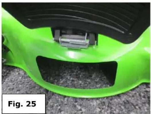
14.5.2 Change to the mower with side discharge
Note: Carry out only with engine stopped and a complete stop of the cutter!
Lift the chute deflector and remove the grass collection container.
Mount the mulching plug into the rear discharge opening (s conversion to mulching mower)
Lift the side cover for side discharge (fig. 25). Install the side ejection guide to the holder of the flap. (fig. 26)
natural_image
Close-up of a green and black plastic car bumper with a metallic bracket, labeled 'Fig. 25' (no other text or symbols)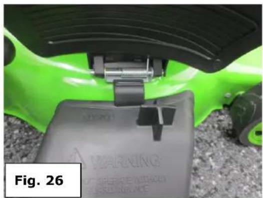
natural_image
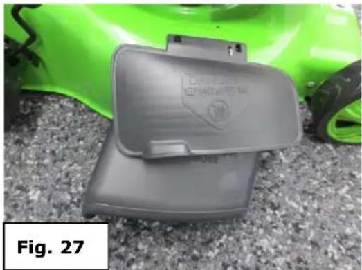
Close-up of a green robotic device with black structural components and a gray base labeled 'MARINE' (no readable text beyond label)Lower the side door - the door is now fixed on the side discharge (fig. 27)
natural_image
Close-up of a gray plastic device with a label, placed on a textured surface next to a green safety helmet (no readable text or symbols)What is mulch?
When mulching the grass or foliage is cut in one step, then fine chopped and then ejected as a natural fertilizer again.
Tips to mulch mowing:
- Regular pruning to max. 2 cm (from 6 cm to 4 cm tall grass)
- The blades should be as sharp
- Mow wet grass
- Adjust the max. an engine speed
- Move the mower at a walking pace
- Regularly clean the mulching plug, the housing interior and the mower blade
15 MAINTENANCE

ATTENT ION

Don't clean or do maintenance on the machine while it is still connected to the power supply:
Damages to machine and injuries might occur due to unintended switching on of the machine!
The machine is low maintenance and contains little parts that must undergo a maintenance operator. Faults or defects that may affect the safety of the machine, must be rectified immediately. Repair work may only be performed by qualified personnel!
At regular intervals, you should also check the bolts and screws are tight. Worn or poorly tightened nuts and bolts can cause serious damage to the engine or frame
Never store with filled tank or gas cans in a closed space where gasoline gases to escape and reach a high temperature and can then inflame the mower. Let the Motor cool the way before storing the mower.
To reduce the risk of fire, clean the mower, especially the engine, exhaust and fuel tank. Remove all grass residues, leaves and grease residues.
Regularly check the condition of the baffle plate and the grass catcher.
Replace these parts if they are damaged.
Before storage of the mower, you should change the oil
Regularly check the oil level and add if necessary, add oil.
Frequently check the mower and ensure that any Grass residues are located under the cover. Grease the wheel axle and the bearings.
Check the blade often to ensure a clean cut. The cutting blade should be sharp and well balanced (no imbalance).
If the blade hits an obstacle, stop the mower.
15.1 Check the oil level
Provide lawn mower with all wheels on the specific section.
Oil tank cap (12) unscrew counter clockwise and wipe dipstick.
Replace the dipstick all the way into the filler pipe.
Pull out the dipstick and check the oil level in a horizontal position.
The oil level must be between the maximum and minimum mark. (see 13.7)
15.2 Maintenance of the air filter
Note: Dirty air filters reduce the engine efficiency by restricting air flow to the carburetor. Regular monitoring, especially in dusty atmosphere is therefore essential!
Attention: Never clean the air filter elements with gasoline or flammable solvents. Fire or explosion!

Do not let the engine run without his air filter: This dust penetrates through the carburetor and causing premature
15.3 Damaged blades
Note: Wear thick gloves for mounting and sharpening the cutting blade. Check that the blade is always well balanced.
If the blade is pushed, despite all precautions for foreign objects / obstacles, first turn off the engine and disconnect the spark plug. If the blade stops, tilt the mower and the blade checked for possible damage.
Deformed or bent blades must not be re-aligned.
Damaged parts must be replaced immediately. After hitting an obstacle, the mower must be checked by an authorized service workshop. Sure before use that knife and knife holder are not damaged. If necessary, replace such parts or checked. Never work with an unbalanced blade - this cause vibration and further damage may result.
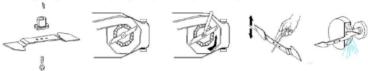
15.4 Change the blade
When changing the blade are to protect your hands, wear appropriate gloves. Before the spark plug is to be deducted.
Use to help a holding pen as a blocking device for the knife. The blade mounting screw has a normal right hand thread. To loosen this screw is best to use a 17 mm socket wrench.
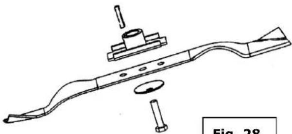
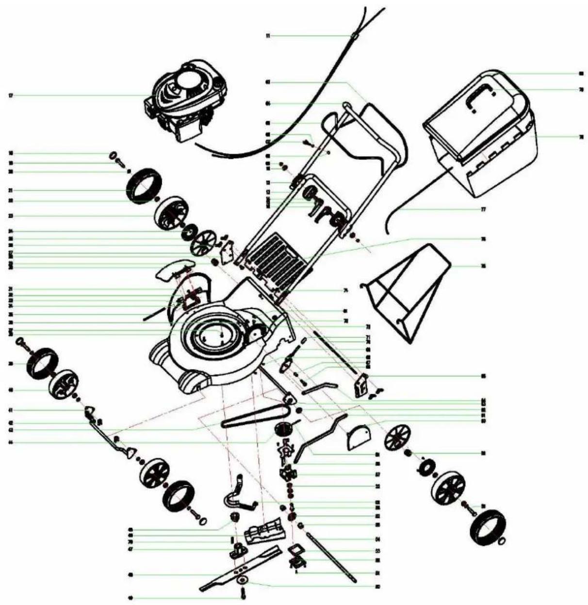
When reassembling the slip clutch on the exact order in which these components were previously installed (Fig. 29).
The screw diameter must be attached to the specified torque of 45 Nm
Make sure that the cutting edges pointing in the direction in which the motor also rotates.
When replacing, use only cutter that match the original enclosed blade in quality and size.
15.5 Sharpen knives
Note: To clean work with, you should raise it at regular intervals. (after about 25 hours)
The cutting blade can be sharpened with a metal file.
Even better is a sharpening / grinding in the customer service workshop. There is also paid particular attention to the fact that is sanded off on each side the same amount, to avoid any imbalance.
The sharpening of the cutting edge may only be up to the impressed mark.
natural_image
Illustration of a mechanical device with five different stages: press, rotary valve, shet machine, hand tool, and spray gun (no text or symbols)Use only original spare parts. Parts of inferior quality can cause serious damage to the unit and may also adversely affect your safety. Please contact your vendor for all required spare parts.
natural_image
Technical line drawing of a mechanical component with multiple parts and a labeled section (no text or symbols on the diagram itself)Fig. 28
16 TROUBLESHOOTING
| Trouble | Possible cause | Solution |
| Engine will not start | Engine brake lever pressed correctly?Engine Reg. Lever inposition ?cable for engine brake adjusted ?plug or plug cap defectfuel tank empty | press/pull brake lever correctlyselect correct positioncheck adjustmentadjusted ?clean or replace plug or caprefuel |
| Rough running, vibrations | Loose engine screwsLoose blade screwdamaged or unbalanced bladefriction clutch worn | tighten screwscheck blade tighteningbalance or replace bladereplace friction washers |
| Engine runs irregular | air filter dirtybent / damaged throttle cablespark plug dirty | clean air filter or replaceadjust / replace cableclean plug |
| Low quality cut | blade is bluntcutting height too lowengine rpm too low | sharpen bladeadjust cutting heightset Eng. Reg. Lever to max. |
| Mower does not collect properly | too low engine rpmcutting height set too low with high grassblade worncatcher fabric clogged | set Eng. Reg. Lever to max.adjust cutting heightreplace bladeclean catcher or replace |
17 UVOD
Spoštovani kupec!
Čestitamo vam za nakup ZIPPER bencinske kosilnice za trato ZI-BRM35/ ZI-BRM56 ZI-BRM60.
natural_image
Close-up of a green industrial component with four bolts and bolts, labeled 'Slika 1' (no other text or symbols visible)
natural_image
Close-up of a green tractor's wheel and bracket assembly with bolts and a labeled component 'Slika 2' (no other text or symbols visible)natural_image
Close-up of a bicycle's side panel with metal clip and attached bracket, labeled 'Bild 3' (no other text or symbols)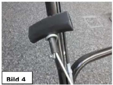
natural_image
Close-up of a bicycle seatbelt with black handle and metal frame, labeled 'Bild 4' (no other text or symbols)natural_image
Close-up of a black mechanical component with attached clamps, placed on a textured surface (no visible text or symbols)
natural_image
Close-up of a black plastic tool with attached black cable and green blade, labeled 'Slika 6' (no other text or symbols visible)20.4 Sestavljanje lovilne posode za travo ZI-BRM60

natural_image
Close-up of a hand using a screwdriver to adjust or install a component, with no visible text or symbols on the main subject.
natural_image
White plastic electronic device casing with a handle and screen, labeled 'Slika 8' (no other text or symbols visible)natural_image
Close-up of a blue industrial container with metal clamps and a black handle (no visible text or symbols)Slika 9
natural_image
Close-up of a modern architectural structure with geometric ceiling and lighting fixtures (no text or symbols visible)Slika 10
natural_image
Close-up of a mechanical component with a grid-patterned ventilation grille and a label 'Slika 11' (no other text or symbols visible)
natural_image
Close-up of a metallic component with grid pattern and label 'Slika 12' (no other text or symbols visible)Pokrov pritrdite na korito lovilne posode ob straneh pri odprtinah (sl. 13).

natural_image
Close-up of a blue plastic container with a handle and ventilation grille, labeled 'Slika 13' (no other text or symbols visible)natural_image
Green Slika 14 robotic vehicle with black wheels and a central vent (no visible text or symbols)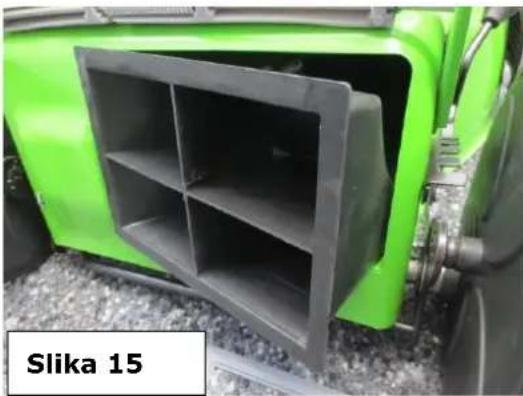
natural_image
Green tractor front view with a black metal enclosure, labeled 'Slika 15' (no other text or symbols visible)natural_image
Close-up of a green agricultural harvester with visible blade and handle, labeled 'Slika 16' (no other text or symbols)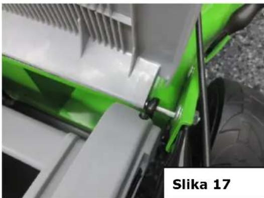
natural_image
Close-up of a green and white industrial machine component with visible cooling fins and mounting brackets (no text or symbols)20.5.3 Montaža odlagalne konzole
-samo pri ZI-BRM56-
natural_image
Green 3D-printed device labeled 'ZIPPER' with a circular vent and handle, mounted on a stand (no readable text beyond label)20.6 Polnjenje goriva
natural_image
Close-up of a hand inserting a black plastic component into a green industrial machine component, labeled 'Slika 19' (no other text or symbols visible)
NAPÓTEK
Poskrbite za to, da prah, nečistoče in voda ne morejo priti v rezervoar za bencin.
natural_image
Close-up of a green lawn mower with a water bottle being poured into it (no visible text or symbols)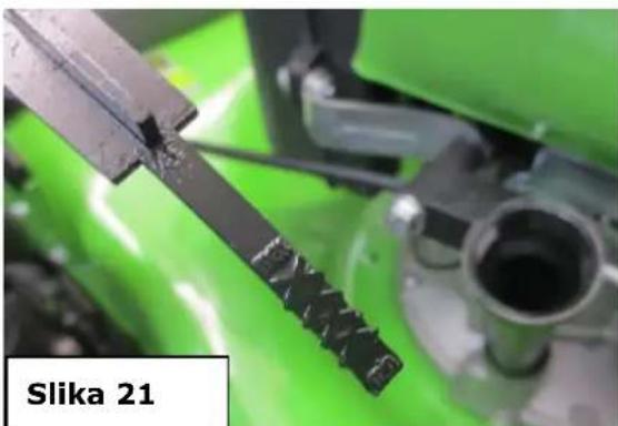
natural_image
Close-up of a mechanical component with green background, no visible text or symbolsPOZOR! Motor je dobavljen brez olja. Vlijte približno 0,6 litra olja, preden zaženete motor!


POZOR!
NA KONCU PREVERITE, ČE SO VSE MATICE IN VIJAKI TRDNO PRITRJENI! MED OBRATOVANJEM STROJ MOČNO VIBRIRA, SLABO PRITRJENI VIJAKI SE LAHKO ODVIJEJO IN IZGUBIJO, KAR LAHKO VODI V NEVARNE SITUACIJE!


POZOR!

natural_image
Close-up of a hand holding a black ergonomic device with a handle, labeled 'Slika 23' (no other text or symbols visible)- Povlecite ročaj motorne zavore (2) na vodilnem ročaju (sl. 22). Izvlecite ročaj zaganjalnika na poteg vrvi (9), dokler ne začutite odpora in ga nato hitro povlecite skozi.
- Čim se motor zažene, vrnite ročaj zaganjalnika na poteg vrvi počasi nazaj v vodilo vrvi.
- Po zagonu motorja, dajte ročico v položaj RUN (sl. 22).
natural_image
Close-up of a green Slika 24 robotic vehicle with visible tire and mechanical components (no text or symbols on the vehicle itself)21.5 Samohodna funkcija/avtomatski kolesni pogon
natural_image
Close-up of a hand holding a black cylindrical device with metal brackets, indoors near a cabinet (no visible text or symbols)21.6 Lovilna posoda za travo
S praznjenjem in čiščenjem lovilne posode za travo skrbite za zračenje mreže.
Praznjenje lovilne posode za travo pred polnjenjem do maksimuma (med 50 in 70%) izboljša kakovost pobiranja pokošene trave.
21.7 ZI-RBM 56 / ZI-BRM 60
natural_image
Close-up of a bright green Slika 26 scooter head panel with visible mechanical components (no text or symbols on the main subject)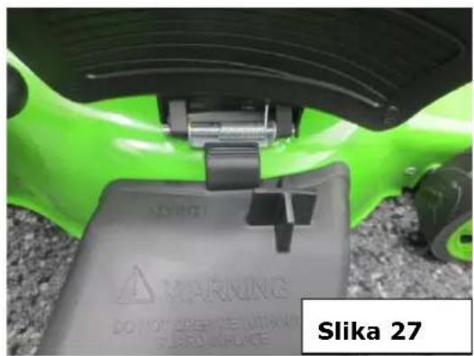
natural_image
Close-up of a gray plastic device with a black logo, placed on a textured surface next to a green car (no visible text or symbols)Kaj je mulčenje?
natural_image
Illustration of five different mechanical or industrial components, including a tool, fan, valve, and cutting tool (no text or symbols present)natural_image
Technical line drawing of a mechanical component with multiple parts and a label 'Slika 29' (no other text or symbols)23 ODPRAVLJANJE NAPAK
24.2 Spare parts order
With original Zipper spare parts you use parts that are attuned to each other shorten the installation time and elongate your machines lifespan.
IMP OR TA NT
The installation of other than original spare parts voids the warranty!
So you always have to use original spare parts
By the order of spare parts use the service formular that you can find at the end of this manual. Make always a note of the type, spare part number and a definition of the machine. That there are no mistakes, we recommend to make a copy of the spare part list where you can mark with a pen the spare parts which you order.
You find the order address in the preface of this operation manual.
| Part No. | Description | Qty | Part No. | Description | Qty |
| 1 | Nail ST4.2x16-C-II | 1 | 61 | oil seal | 1 |
| 2 | cover | 1 | 62 | retaining ring | 2 |
| 3 | traction | 1 | 63 | valve guides | 2 |
| 4 | nut M6 | 3 | 64 | piston pin | 1 |
| 5 | windscreen | 1 | 65 | shaft key 4.0x6.5x16 | 1 |
| 6 | anti casing | 1 | 66 | connecting rod shank | 1 |
| 7 | clamp | 1 | 67 | oil level gauge | 1 |
| 8 | bolt | 3 | 68 | gasket series | 8 |
| 9 | flywheel nut | 1 | 69 | oil filler pipe | 1 |
| 10 | ignition knob bolt | 2 | 70 | O ing 20X2.65 | 1 |
| 11 | pipeline | 1 | 71 | oil drain plug screw | 1 |
| 12 | wheelbush | 1 | 72 | gasket series | 1 |
| 13 | blower | 1 | 73 | lower crankcase | 1 |
| 14 | flywheel parts | 1 | 74 | flat washer | 1 |
| 15 | nail M6X20 | 2 | 75 | speed governor | 1 |
| 16 | wind deflector | 1 | 76 | oil block | 1 |
| 17 | head oilseal | 2 | 77 | speed governor plate | 1 |
| 18 | bolt M6X25 | 1 | 78 | bolt M6X12 | 1 |
| 19 | ignition coil | 1 | 79 | crankcase gasket | 1 |
| 20 | upper crankcase | 1 | 80 | crankcase pin | 2 |
| 21 | bolt block | 2 | 81 | crankshaft gear washer | 1 |
| 22 | bolt | 1 | 82 | crankshaft gear | 1 |
| 23 | oil ring comp | 1 | 83 | crankshaft | 1 |
| 24 | piston ring 2 | 1 | 84 | connecting rod cap | 1 |
| 25 | piston ring 1 | 1 | 85 | connecting rod bolts | 2 |
| 26 | cylinder head gasket | 1 | 86 | bearing 205 | 1 |
| 27 | locating bush | 2 | 87 | oil seal | 1 |
| 28 | exhaust valve | 1 | 88 | idle adjusting spring | 1 |
| 29 | intake valve | 1 | 89 | throttle rod | 1 |
| 30 | exhaust valve housing washer | 1 | 90 | angular rod | 1 |
| 31 | intake valve housing washer | 1 | 91 | fastening bolt | 1 |
| 32 | cylinder head | 1 | 92 | accelerate arm | 1 |
| 33 | graphite pad | 1 | 93 | air choke rod | 1 |
| 34 | airflow blocker | 1 | 94 | pressure regulation spring | 1 |
| 35 | exhaust muffler | 1 | 95 | bolt M5X20 | 1 |
| 36 | studs | 2 | 96 | bolt M5X35 | 1 |
| 37 | enclosure | 1 | 97 | governor plate | 1 |
| 38 | washer 5 | 2 | 98 | governing spring | 1 |
24.2 ZI-BRM60
| Part No. | Description | Qty | Part No. | Description | Qty |
| 1 | ST screw ST3.5*20 | 2 | 42 | front wheel washer | 2 |
| 2 | active wheel cover | 1 | 43 | belt | 1 |
| 3 | clutch control lever | 1 | 44 | driven wheel | 1 |
| 4 | master control rob | 1 | 45 | driven strap wheel | 1 |
| 5 | control lever | 1 | 46 | shield | 1 |
| 6 | hex.nut M6 | 3 | 47 | blade support | 1 |
| 7 | cord hook | 1 | 48 | blade | 1 |
| 8 | cap nut M6 | 2 | 49 | Blade bolt | 1 |
| 9 | Type 2 nonmetal embedded a lock nut M8 | 2 | 50 | wing gasket | 1 |
| 10 | lock nut set | 2 | 51 | hex. Bolt M5*10 | 8 |
| 11 | Speed regulation and cable components | 1 | 52 | Umbrella tooth cabinet | 1 |
| 12 | Coupling gear | 4 | 53 | Cabinet gaskets | 1 |
| 13 | Coupling gear | 1 | 54 | Transmission shaft | 1 |
| 14 | locking bolt | 2 | 55 | oil bearing | 2 |
| 15 | spring cylindrical pin | 2 | 56 | Umbrella tooth | 1 |
| 16 | knob | 2 | 57 | Umbrella tooth cabinet | 1 |
| 17 | 1P65F engine assembly | 1 | 58 | wheel guide plate | 1 |
| 18 | wheel cover | 4 | 59 | left gear 14 | 1 |
| 19 | left shaft 12 (right shaft 12) | 2 | 60 | Protection to reset to higher | 1 |
| 20 | washer 12 | 6 | 61 | front bindiny mechanism | 1 |
| 21 | rear wheel | 2 | 62 | Rolling bearing 6001(12*28*8) | 2 |
| 22 | Rolling bearing 61901 (12*24*6) | 8 | 63 | rear long rob shaft | 1 |
| 23 | 200 hub | 2 | 64 | rear bindiny mechanism | 1 |
| 24 | ST screw ST4.2*20 | 2 | 65 | handrail bracket | 1 |
| 25 | gear 55 | 2 | 66 | handle bolt | 1 |
| 26 | butterfly nut M8 | 4 | 67 | handle bush | 1 |
| 27 | dust-proof cover | 2 | 68 | hex. Bolt M8 | 2 |
| 28 | Handrail or so stents | 1 | 69 | adjustment handle | 1 |
| 29 | left gear 14 | 1 | 70 | cover plate shaft | 1 |
| 30 | side discharge plate | 1 | 71 | handle | 1 |
| 31 | side discharge cover | 1 | 72 | gear plate | 1 |
| 32 | wrested spring | 2 | 73 | hex.bolt M8*15 | 2 |
| 33 | M6*15 | 3 | 74 | semicircle coach bolt diameter M8*20 | 4 |
| 34 | Side row stents | 1 | 75 | crasscather bracket | 1 |
| 35 | Side row stents shaft | 1 | 76 | rear cover | 1 |
| 36 | pan-head screw with tapping screw | 2 | 77 | nylon rope | 1 |
| 37 | Hex.Bolt M8*25 | 3 | 78 | grasscatcher assembly | 1 |
| 38 | deck | 1 | 79 | Grass box handle | 1 |
| 39 | front wheel | 2 | 80 | Grass box | 1 |
| 40 | 178 hub | 2 | 81 | spring cylindrical pin 5*80 | 1 |
| 41 | front Long pole shaft | 1 | 82 | Umbrella tooth | 1 |
25 KONFORMITÄTSERKLÄRUNG / CERTIFICATE OF CONFORMITY
| CE | Inverkehrbringer / DistributorZ.I.P.P.E.R® Maschinen GmbHA- 4707 Schlüsslberg, Gewerbepark 8Tel.: +43 7248 61116-701; Fax.: +43 7248 61116-721www.zipper-maschinen.atinfo@zipper-maschinen.eu |
| Bezeichnung / name | |
| Benzinrasenmäher / Gasoline lawn mower / Bencinska kosilnica za trato | |
| Type / model | |
| ZI-BRM35, ZI-BRM56, ZI-BRM60 | |
| EG-Richtlinie / EC-directive(s) | |
| 2006/42 EG2004/108 EG2000/14 EG2004/26 EG | |
| Angewandte Normen / applicable Stanards | |
| EN 836:+A1+A2+A3+AC; EN ISO 14982; EN ISO 3744;EN ISO 11094 | |
Hereby we declare that the mentioned machine fulfils the relevant requirements of the above stated EC-Directives. Any manipulation of the machines not authorized by us renders this document invalid.
Company ZIPPER Maschinen GmbH grants for mechanical and electrical components a warranty period of 2 years for amateur use; and warranty period of 1 year for professional use, starting with the purchase of the final consumer. In case of defects during this period, which are not excluded by paragraph 3, ZIPPER will repair or replace the machine at its own discretion.
2.) Report:
In order to check the legitimacy of warranty claims, the final consumer must contact his dealer. The dealer has to report in written form the occurred defect to ZIPPER. If the warranty claim is legitimate, ZIPPER will pick up the defective machine from the dealer. Returned shippings by dealers which have not been coordinated with ZIPPER, will not be accepted and refused.
3.) Regulations:
a) Warranty claims will only be accepted, when a copy of the original invoice or cash voucher from the trading partner of ZIPPER is enclosed to the machine. The warranty claim expires if the accessories belonging to the machine are missing.
b) The warranty does not include free checking, maintenance, inspection or service works on the machine. Defects due to incorrect usage of the final consumer or his dealer will not be accepted as warranty claims either. Some examples: usage of wrong fuel, frost damages in water tanks, leaving fuel in the tank during the winter, etc.
c) Defects on wear parts are excluded, e.g. carbon brushes, collection bags, knives, cylinders, cutting blades, clutches, sealings, wheels, saw blades, splitting crosses, riving knives, riving knife extensions, hydraulic oils, oil/air/fuel filters, chains, spark plugs, sliding blocks, etc.
d) Also excluded are damages on the machine caused by incorrect or inappropriate usage, if it was used for a purpose which the machine is not supposed to, ignoring the user manual, force majeure, repairs or technical manipulations by not authorized workshops or by the customer himself, usage of non-original ZIPPER spare parts or accessories.
e) After inspection by our qualified personnel, resulted costs (like freight charges) and expenses for not legitimated warranty claims will be charged to the final customer or dealer.
f) In case of defective machines outside the warranty period, we will only repair after advance payment or dealer's invoice according to the cost estimate (incl. freight costs) of ZIPPER.
g) Warranty claims can only be granted for customers of an authorized ZIPPER dealer who directly purchased the machine from ZIPPER. These claims are not transferable in case of multiple sales of the machine.
4.) Claims for compensation and other liabilities:
The liability of company ZIPPER is limited to the value of goods in all cases. Claims for compensation because of poor performance, lacks, damages or loss of earnings due to defects during the warranty period will not be accepted. ZIPPER insists on its right to subsequent improvement of the machine.
28 GARANCIJA
1.) Garancija:
service inquiry spare part inquiry guarantee claim
Please describe amongst others in the problem: What has cause the problem/defect, what was the last activity before you noticed the problem/defect? For electrical problems: Have you had checked you electric supply and the machine already by a certified electrician?
3. Bitte beachten
/ Additional information
INCOMPLETELY FILLED SERVICE FORMS CANNOT BE PROCESSED! FOR GUARANTEE CLAIMS PLEASE ADD A COPY OF YOUR ORIGINAL SALES / DELIVERY RECEIPT OTHERWISE IT CANNOT BE ACCEPTED. FOR SPARE PART ORDERS PLEASE ADD TO THIS SERVICE FORM A COPY OF THE RESPECTIVE EXPLODED DRAWING WITH THE REQUIRED SPARE PARTS BEING MARKED CLEARLY AND UNMISTAKABLE. THIS HELPS US TO IDENTIFY THE REQUIRED SPARE PARTS FASTLY AND ACCEL- ERATES THE HANDLING OF YOUR INQUIRY.