
ZIMOS4TA - Lawn mower Zipper - Free user manual and instructions
Find the device manual for free ZIMOS4TA Zipper in PDF.

| Product type | Lawn mower (brushcutter) |
| Brand | Zipper |
| Model | ZIMOS4TA |
| Category | Lawn mower |
| Power source | Petrol (4-stroke engine) |
| Engine type | 4-stroke, air-cooled |
| Recommended engine oil | 15W40 |
| Cutting tool | Brushcutter blade and spool of line (line head) |
| Starting system | Recoil starter |
| Ignition | Spark plug (gap 0.5-0.7 mm) |
| Air filter cleaning | Every 20 to 30 service hours |
| Spark plug replacement | Every 25 service hours |
| Engine oil change | Every 100 service hours |
| Personal protective equipment | Helmet, hearing protection, gloves, safety shoes, safety glasses |
| Safety distance | Minimum 15 meters around the machine |
| Warranty (non-commercial use) | 2 years |
| Warranty (commercial use) | 1 year |
| Spare parts | Available from the manufacturer (see manual) |
| Country of origin | Austria |
| Manufacturer contact | ZIPPER MASCHINEN GmbH, 4707 Schlüsslberg, Austria |
Frequently Asked Questions - ZIMOS4TA Zipper
User questions about ZIMOS4TA Zipper
0 question about this device. Answer the ones you know or ask your own.
Ask a new question about this device
Download the instructions for your Lawn mower in PDF format for free! Find your manual ZIMOS4TA - Zipper and take your electronic device back in hand. On this page are published all the documents necessary for the use of your device. ZIMOS4TA by Zipper.
USER MANUAL ZIMOS4TA Zipper
natural_image
Green manual tool with tripod and base, no visible text or symbolsZI-MOS4TA
EAN: 9120039232966


ATTENTION: 4-stroke-engine Check Oil (15W40)!
11.1 Intended Use....19
11.2 Safety instructions .... 19
11.3 Remaining risk factors.... 21
11.4 Personal wear 22
11.5 Belt....22
12 ASSEMBLY 23
12.1 Delivery content 23
12.2 Assembly 23
13 OPERATION 25
13.1 Operation instructions.... 25
13.2 Engine Start.... 25
13.3 Stop the engine 25
14 MAINTENANCE 26
14.1 Cleaning 26
14.1.1 Cleaning the air filter 26
14.1.2 Check the spark plug 26
14.1.3 Engine oil change / engine oil check 27
Engine oil check: 27
14.2 Storage.... 27
14.3 Disposal....27
15 TROUBLE SHOOTING 28
EN EC-CONFORM – This product complies with the EC-directives.
EN READ THE MANUAL! Read the user and maintenance manual carefully and get familiar with the controls in order to use the machine correctly and to avoid injuries and machine defects.
EN ATTENTION! Ignoring the safety signs and warnings applied on the machine as well as ignoring the security and operating instructions can cause serious injuries and even lead to death.
EN Personal protective equipment!
natural_image
Five blue circular icons representing different workplace safety symbols: head, helmet, foot, hand, and person (no text or labels)
EN Hot surface, Burn hazard!
EN Highly flammable! Naked flames prohibited
EN Danger of Intoxication (CO)! Only use outdoors and far from open windows and vents
EN Solid Objects can be thrown away!
EN Keep safe distance!
natural_image
Product photo of a green power tool with attached components and a small inset image showing a grid of black tools (no visible text or symbols)3.2 Komponenten / Components / Componenti / Composants

| 1 | Motor / Engine /Motore / Moteur | 7 | Verbindungsstück / Connector / Pezzo di collegamento / Pièce de raccordement |
| 2 | Gurtöse / Belt eyelet / Occhiello della cintura / Anneau de transport | 8 | Handgriff / Handle / Magnilia / Poignée |
| 3 | Schutzabdeckung / Safety covcer / Copertura protettiva / Cache de protection | 9 | Gurt / Belt / Cinturino / Sangle |
| 4 | Fadenmesser / Nylon cutter blade Coltello filo / Coupe-fil | 10 | Mähmesser 3 Zahn / 3-tooth blade / Lama di taglio 3 denti / Lame 3 dents |
| 5 | Fadenspule / Nylon cutter / Bobina / Bobine de fil | 11 | Mähmesser 8 Zahn / 8-tooth blade / Lama di taglio 8 denti / Lame 8 dents |
| 6 | Stange / Pole / Asta / Perche | 12 | ZI-BR3 (en option) |
3.3 Technische Daten /Technical details / Data tecnici / Données techniques
| ZI-MOS4TA | |
| Motortyp / Engine type / Tipo motore / Type de moteur | 4-Takt |
| Motorleistung / Engine power /Potenza motore / Puissance du moteur | 1,2 kW |
| Hubraum / Displacement / Cilindrata / Cylindrée | 38,9 cm ^3 |
| Leerlaufdrehzahl / Idle running speed /Velocità a vuoto / Régime à vide | max. 3200 min ^-1 |
| max. Drehzahl Schneidgarnitur /max. rotational speed cutting set /max. set di taglio rapido / Vitesse de rotation max. de lagarniture de coupe | 9500 min ^-1 |
| Stange / Pole dimension / Asta / Perche | 1500 mm ∅28mm |
| Durchmesser Aufnahmewelle / Shaft diameter /Diametro albero / Diamètre de l'arbre de réception | 8 mm |
| Zündung / Ignition type / Accensione / Allumage | CDI |
| Tankvolumen / Fuel tank capacity /Volume serbatoio / Volume du réservoir | 0,65 l |
| Kraftstoff / Fuel / Carburante / Carburant | Benzin ROZ 95Unleaded gasoline RON 95 |
| Motoröl / Engine oil /Olio motore / Huile du moteur | 110 ml (15W40) |
| Gewicht / Weight /Peso / Poids | 7,8 kg |
| Starter / Starter /Avviamento / Démarreur | easy Starter Seilzug |
| Garantierter Schall-Leistungspegel LWA /Guaranteed sound power level LWA /Livello di potenza sonora garantito LWA /Niveau de puissance acoustique garanti LWA | 114 dB (A) |
| Vibration / Vibration / Vibrazione / Vibrations | ~5,7 m/s ^2 k:1,5m/s ^2 |
| Zündkerzentype / spark-plug type / | A5RTC |
| Fadenspule / Bobbin /Bobina / Bobine de fil | |
| Maximale Schnittbreite / Max cutting width / Larghezza ditaglio massima / Largeur de coupe maximale | 420 mm |
| Fadenlänge /Thred length / Lunghezza del filo / Longueur de fil | 4,5 m |
| Fadenstärke / Thred sickness / Spessore del filo / Épaisseur defil | ∅ 2,4 mm |
| Mähmesser / Mowing blade / Lama falciante / Lame de taille | |
| Mähmesser 3 Zahn / 3-tooth mowing blade / Lama di taglio 3 denti / Lame 3 dents | ∅305 x ∅25,4 x 1,6mm |
| Mähmesser 8 Zahn / 8-tooth mowing blade / Lama di taglio 8 denti / Lame 8 dents | ∅305 x ∅25,4 x 1,3mm |
4 VORWORT (DE)
Montage Handgriffe
natural_image
Close-up of a mechanical component with a highlighted circular feature and arrow indicator (no text or symbols)
natural_image
3D rendered mechanical part with numbered annotations (5 and 6), no readable text or symbols beyond labels
natural_image
Close-up of a mechanical component with a circular component and yellow alignment lines (no visible text or symbols)
natural_image
Mechanical assembly diagram showing a rotating component with a yellow curved arrow indicating rotation (no text or symbols present)Montage Mähmesser:
This manual contains important information and advice for the correct and safe use and maintenance of the brush cutter ZI-MOS4TA.
Following the usual commercial name of the machine (see cover) is substituted in this manual with the name "machine".
The manual is part of the machine and may not be stored separately. Read it profoundly before first use of the machine and keep it for later reference. When the machine is handed to other persons always put the manual to the machine.
Please follow the security instructions!
Please read the entire manual, to prevent misunderstandings, machine damage or even injuries!

Due to continuous development of our products illustrations, pictures might differ slightly.
If you however find errors in this manual, please inform us.
Technical changes excepted!
Copyright law
© 2017
This manual is protected by copyright law – all rights reserved. Especially the reprinting as well as the translation and depiction of pictures will be prosecuted by law. Court of jurisdiction is the Landesgericht Linz or the competent court for 4707 Schlüsslberg, AUSTRIA.
Customer Support
The machine must only be used for its intended purpose! Any other use is deemed to be a case of misuse.
To use the machine properly you must also observe and follow all safety regulations, the assembly instructions, operating and maintenance instructions lay down in this manual.
All people who use and service the machine have to be acquainted with this manual and must be informed about the machine's potential hazards.
It is also imperative to observe the accident prevention regulations in force in your area.
The same applies for the general rules of occupational health and safety.
The machine is used for:
Mowing and trimming grass at moderate and non-slippery terrain and for cutting twigs and hedges.
Any manipulation of the machine or its parts is a misuse, in this case ZIPPER-MASCHINEN and its sales partners cannot be made liable for ANY direct or indirect damage.

WARNING
- Do not change the mowing attachment!
- Using saw blades for the machine is prohibited!
- Damaged cutting tools may be not straightened or welded in no case
HIGHEST RISK OF INJURY!
11.2 Safety instructions
Missing or non-readable security stickers have to be replaced immediately!
To avoid malfunction, machine defects and injuries, read the following security instructions!
The locally applicable laws and regulations may specify the minimum age of the operator and limit the use of this machine!
• Use the machine only in good enough light to allow a safe operation can be guaranteed.
- In tiredness, decreased concentration or under the influence of alcohol or drugs, the work on the machine is prohibited!
- Caution in slippery conditions - slip hazard - risk of injury. When working, robust and non-slip footwear. Slides / stumble / traps are a major cause of serious injury or death.
- The machine may only be operated by trained personnel.
- Unauthorized persons, especially children and not trained personnel must be kept away from the running machine!
• If you pass the machine to third, these instructions must be attached to the machine.
- Before each use, the reliability of the machine is to be checked (tightness of the cutting tool, the proper function of the throttle lever)
- Danger of burns! During the operation flow of hot exhaust gases and engine parts such as the carburettor and engine become hot.
- Never place a hot brush cutter in dry grass or other easily flammable materials.
• After the operation, the machine must cool down. Otherwise there is an imminent risk of burns
- WARNING: Gasoline is highly flammable!
- Smoking and open flames are prohibited during refuelling. Do not refuel when the engine and carburettor are still very hot.
- Refuel only outdoors or in a well ventilated area.
- Avoid contact with skin and clothes (fire hazard).
- Check after refuelling tank cap and check for leaks.
- Start the engine at least 3 meters from the tank location.
- Spilled fuel is wipe immediately.
- Work attentively, safety conscious and always be fully aware safe stand when working! Caution on uneven work surfaces and work surfaces with a slope!
-
Never cutting:
-
above hip height
- on a ladder
-
on trees
-
Regular breaks reduce the security risk to loss of control due to fatigue. Change the working position over again.
- Avoid abnormal posture.
- At idle, the blade should not rotate!
• The maximum shaft speed must not exceed the specified speed. Checked settings! - No other person shall remain within 15m!
- This distance also adhere to things! Danger of damage!
• Solid objects, stones, metal parts, or the like can be thrown out - risk of injury! - Use personal safety equipment: ear protectors, safety goggles, safety shoes and safety helmet when working with the machine
- Never leave the machine running unattended! Before leaving the working area switch the machine off and wait until the machine stops.
- Switch off the machine before maintenance or adjustment.
- Storage always with an empty tank in a safe place.
- Do not grab in the cutting tool while it is rotating.
• Take care that you do not get under the cutting tool!
• Always use the correct cutting tool for the work to be done. - Do not operate in an enclosed or confined areas.
- Exhaust contains poisonous carbon monoxide. The exposure can cause unconsciousness and death.
- Before the start, after the failure or shock, be sure to check the device and make sure that it is in good condition.
- Wear firm gloves when you use the brush cutter or if you install or remove the cutting blade.
TRANSPORT NOTES:
- Switch off the engine
- Fit the blade guard
- Secure the machine
• Empty tank completely, avoid fuel spillage
• To avoid damage to the device never drag but always lift correctly.
STORAGE NOTES:
- Remove and clean thread head and cutter blade
- Fit the blade guard
- Clean the machine and dry
• Empty Tank completely, avoid fuel spillage
• Store in a dry, out of reach of children place, well packaged (protection against cuts)
11.3 Remaining risk factors
Working with a brush cutter always poses some risks that cannot be eliminated entirely:
- Noise: Working for a long time can damage your hearing if you do not have a very good hearing protection.
- Risks of injury:
Be aware that the cutter might stall and lead you to fall.
Small objects might be caught by the machine and catapulted into the air.
The contact with the rotating moving cutter causes severe injuries! Protect especially your feet by wearing reinforced security shoes.
Never get with your fingers or hands near the rotating moving cutter.
Do not touch the muffler or other machine components during operation – They become hot!
- Risk to the hands or fingers:
Access while it is working in the mowing apparatus. After the operation, the machine must cool down.
Otherwise, there is an acute risk of scalding! Wear protective gloves to avoid injury
- Vibration:
The declared vibration emission value has been for a standardized test is measured and can be used to compare one tool with another electric are.
The declared vibration emission value may also be used for a preliminary assessment of exposure.
- Warning:
Emission level of vibration can be different from the specified value during the actual use of the electric tool, depending on the manner in which the power tool is used
- Kickback
When working with metal cutting blades, it can, if fixed objects (trees, branches, stones, or the like) are involved, come to a check of the entire unit or to an abrupt train forward.
This check occurs suddenly without warning and can lead to loss of control of the unit and endanger the user and bystanders.
Special Threatened in poor visibility areas and dense vegetation.
So keep checking by kickback:
- Hold the unit with both hands when working securely.
- Be easily spread on a secure footing and keep your feet always count on you with a possible setback.
- Do not overestimate yourself and keep it in working balance at all times.
• The knife should have reached full operating speed before cutting begins. - When clearing stones and debris can be thrown and cause serious injury.
Make sure that the cover is securely mounted.
Be rotating parts (blades) mounted incorrectly, this can lead to serious accidents.
Check before starting work, the cutting blade for tight fit
11.4 Personal wear
A. Security helmet
B. Hearing protection
C. Face production
D. Belt
E. Safety gloves
F. Safety cover of moving unit
G. Safety shoes
H. Working trousers

NOTICE
The tool only use before using adapted to the operator, shoulder strap. Never operate the trimmer with one hand!
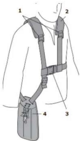
11.5 Belt
- Pull the belt over your shoulders 2.
- Close the belt lock 3.
- Adjust the belt length at the belt tensioner 1 of the shoulder straps so that the machine holder 4 is at hip height.
- Adjust the belt lengths so that the machine weight is distributed evenly onto the two shoulders.
- Hook the belt with the quick coupling into the belt eyelet of the machine.
Never work without using the belt
12 ASSEMBLY
12.1 Delivery content
Please check the product contents immediately after receipt for any eventual transport damage or missing parts. Claims from transport damage or missing parts must be placed immediately after initial machine receipt and unpacking before putting the machine into operation.
12.2 Assembly
The machine comes partly assembled and the components that have been disassembled for transport must be assembled as described below and the fuel and engine oil must be filled.
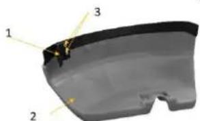
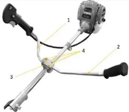 | Assemble handlesInsert the handle (1) and handle (2) into the holder (3) and fix them to the machine with the four screws (4) |
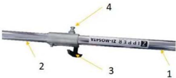
 | Fixing the cable/rope pullFix cable/rope (2) in clamp (1) and fix clamp (1) on rod |
 | Connecting the rodPut the two parts (1) and (2) of the rod together and connect them by means of the bolt (4) and handle (3) |
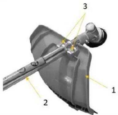
 | Assembly nylon cutter bladeAssemble the nylon cutter blade (1) onto the guard (3) with two screws. |
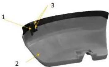
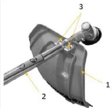
Assembly safety guard
Assemble the safety guard (1) to the rod using two screws (3)

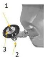
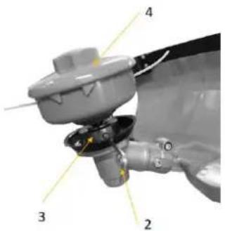
Assembly nylon cutter
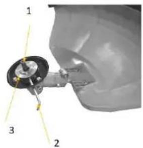
- Fix the upper holder (3) with the Allen key (2). (Push the Allen key through both holes. The hole on the upper holder (3) must first be aligned by turning.
- put the nylon cutter (4) on the thread (1) and tighten it
NOTE
Left-hand thread


natural_image
Close-up of a mechanical component with a highlighted circular feature and arrow indicator (no text or symbols)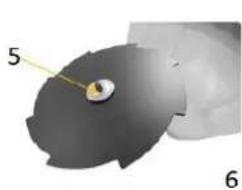
natural_image
3D rendered mechanical part with numbered annotations (5 and 6), no readable text or symbols beyond labels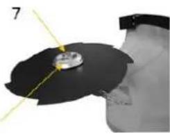
natural_image
Close-up of a mechanical component with a circular component and yellow alignment lines (no visible text or symbols)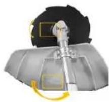
natural_image
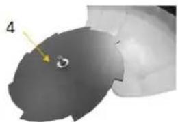
Mechanical assembly diagram showing a rotating component with a yellow curved arrow indicating rotation (no text or symbols present)Assembly tooth blade:
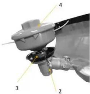
- Fix the upper holder (3) with the Allen key (2). (Push the Allen key through both holes. The hole on the upper holder (3) must first be aligned by turning.
- Attach the tooth blade (4)
- Attach the flange (5)
- Attach the flange (6) and nut (7) und fasten the nut (7)
NOTE
Left-hand thread
13 OPERATION
Machine to be operated in a perfect state only. Inspect the device visually every time it is to be used. Check in particular the safety equipment, electrical controls, electric cables and screwed connection for damage and if tightened properly. Replace any damaged parts before operating the device.
13.1 Operation instructions
NOTICE
- Shut off the machine and let it cool down before start any cleaning, upkeep, checks or maintenance!
- Operate the machine always with belt!
- In dangerous situations detach the machine with the quick release from shoulder strap
- Make sure the fuel and tank are in perfect condition before each start!
WARNING

ATTENTION! For transport engine oil has been drained. Fill up with 4-stroke quality motor oil before first operation! Failure to do so will result in permanent motor damage and void guarantee!
13.2 Engine Start

- switch main switch (1) to "I" = machine ready for operation
- set the start speed: Press release lever (2) and throttle lever (4) and press holder (3)
- close the choke (5) (in upper position)
- press primary pump (6) 2-3 times
- grasp the start cable and pull it slowly until resistance is felt, let the cable rewind slightly from this point and pull it forcefully.
- when the engine runs smoothly, open the choke (5) (lower position)
13.3 Stop the engine
- Release the throttle lever and set the mainswitch (1) to position off „0“.
14 MAINTENANCE


ATTENTION
No cleaning, upkeep, checks or maintenance when machine is running
Shut off the machine and let it cool down before start servicing!
The machine does not require intense maintenance. However, to ensure a long lifespan, we strongly recommend following the upkeep and maintenance plan.
Repairs must be carried out by specialists! Use original ZIPPER parts only!
Ware safety gloves if you are work on the cutting tool!
Damaged cutting tools may never be straightened or welded!
NOTICE
Only a properly maintained equipment may be a satisfactory tool. Care and maintenance deficiencies can cause unpredictable accidents and injuries.
Repairs should be performed only by authorized service centers.
Improper operation may damage the equipment or endanger your safety.
| Controls for the maintenance of the machine | |
| Loose or lost screws, nuts, bolts | Regularly prior to each operation |
| Damage of any part of the machine | Regularly prior to each operation |
| Damage of cutting tools | Regularly prior to each operation |
| Fuel tank of tightness | Regularly prior to each operation |
| Machine cleaning | Regularly after operation |
| Cleaning spark plug | Every 25 working hours |
| Cleaning air filter | Every 20-30 working hours |
14.1 Cleaning
Clean the machine and the working attachment from soil, dust, grass, chips, and small twigs, etc. Clean the machine housing with a wet cloth and a mild detergent.
NOTE
Do not use cleaning agents or solvents; these could attack the plastic parts of the machine!
Put on all coatless flats a thin coat of oil.
14.1.1 Cleaning the air filter
The air filter has to be cleaned approx. every 20-30 working hours. This may vary depending on the air quality of your working area.
Polluted and clogged air filters reduce the engine output by far and may lead to engine damage.
To clean the air filter just remove the black air filter cover and take the filter out. Wash it in a mild water based solvent, squeeze it out, let it dry and put it back again.
14.1.2 Check the spark plug
- Clean of debris with metal brush.
- Check spark plugs match of 0.5-0.7mm
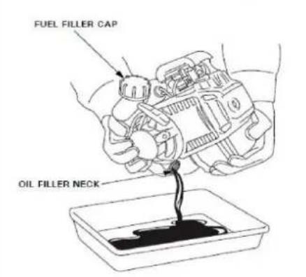
14.1.3 Engine oil change / engine oil check
NOTICE


Waste oils are toxic and must not be released into the environment! Contact your local authorities for information on proper disposal.
 | Engine oil check:Regularly prior to each operation!Remove the oil filler cap/dipstickMinimum: LOWER LIMITMaximum. UPPER LIMITFill up with engine oil if the level is below the minimum.Engine oil change:After 100 working hoursDrain the oil into a suitable containerFill in new motoroil (15w40) |
 |
14.2 Storage
If the machine will be stored longer than 30 days:
- Let the machine cool down.
• Empty Tank completely, avoid fuel spillage. - Remove and clean thread head and cutter blade
- Fit the blade guard
- Clean the machine and dry
• Store in a dry, out of reach of children place, well packaged (protection against cuts)
14.3 Disposal

Do not dispose the machine, machine components fuel and oil in residual waste. Contact your local authorities for information regarding the available disposal options. When you buy at your local dealer for a replacement unit, the latter is obliged to exchange your old.
15 TROUBLE SHOOTING
WARNING

Hot surfaces and rotating machine parts while the engine is running can cause serious injury or even death. Always stop the machine before carrying out troubleshooting work and secure it against unintentional restarting.
| Trouble | Possible cause | Solution |
| Engine does not start | Incorrect starting sequence | Observe the correct starting sequence |
| Dirty air filter | Clean/replace air filter | |
| No fuel supply | Refuel | |
| Fault in the fuel line | Check the fuel line for kinks or damages | |
| Engine flooded. | Screw off, clean and dry the spark plug. Then pull the cranking rope several times and reinstall the spark plug | |
| Spark plug connector not placed on. | Place on the spark plug connector | |
| No ignition spark | Clean/replace spark plugCheck ignition cable | |
| Engine starts and is stalled immediately | Incorrect idle adjustment | Contact customer service |
| Machine works with interruptions | Carburetor incorrectly adjusted | Contact customer service |
| Spark plug fouled | Clean/replace spark plugCheck spark plug connector | |
| Machine does not work with full performance | Machine overloaded | Too much pressureCutting material too tough |
| Dirty air filter | Clean/replace air filter | |
| Carburetor incorrectly adjusted | Contact customer service | |
| Blade rotates at idling | Idle speed too high | Adjust a lower idle speed |
| Blade rotates but has no power | Choke is ON | Set Choke to OFF |
| Bad cuts | Foreign material wrapped, grass around the sheet | Shut machine off, wait until cutter stands still, remove the winded up material |
| Long grass | Remove material | |
| Blunt saw blade | Sharpen or replace saw blade |

NOTICE
Should you in necessary repairs not able to properly to perform or you have not the prescribed training for it always attract a workshop to fix the problem.
Maniglia
natural_image
Close-up of a metallic mechanical component with a circular feature and a yellow arrow pointing to it (no text or symbols visible)
natural_image
3D rendered mechanical part with numbered annotations (5 and 6), no readable text or symbols beyond labels
natural_image
Close-up of a mechanical component with yellow alignment lines and a small circular feature, no visible text or symbols
natural_image
Mechanical assembly diagram showing a rotating component with a yellow curved arrow indicating rotation (no text or symbols present)Cher client, chère cliente,
Poignée

natural_image
Close-up of a metallic mechanical component with a circular feature and a yellow arrow pointing to it (no text or symbols visible)
natural_image
3D rendered mechanical part with numbered annotations (5 and 6), no readable text or symbols beyond labels
natural_image
Close-up of a mechanical component with yellow alignment lines and a small circular feature, no visible text or symbols
natural_image
Mechanical assembly diagram showing a rotating component with a yellow curved arrow indicating rotation (no text or symbols present)(EN) With original ZIPPER spare parts you use parts that are attuned to each other shorten the installation time and elongate your machines lifespan.
IMP OR TAN T
The installation of other than original spare parts voids the warranty!
So you always have to use original spare parts
When you place a spare parts order please use the service formular you can find in the last chapter of this manual. Always take a note of the machine type, spare parts number and partname. We recommend to copy the spare parts diagram and mark the spare part you need.
You find the order address in the preface of this operation manual.
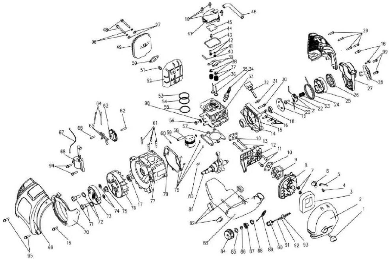
| NO. | PART NAME | QTY. | NO. | PART NAME | QTY. | NO. | PART NAME | QTY. |
| 1 | Gear Case Ass'y | 1 | 30 | Rubber Cover B | 1 | 59 | Spring | 1 |
| 2 | Stop Ring 26 | 1 | 31 | Linker | 1 | 60 | Box,Left | 1 |
| 3 | Stop Ring 10 | 1 | 32 | Stop Ring 15 | 1 | 61 | Handgrip | 1 |
| 4 | Bearing 6000-2RS/P6 | 2 | 33 | Bearing 6202-2RZ/P6 | 3 | 62 | Bolt M6 × 25 | 2 |
| 5 | Pinion | 1 | 34 | Stop Ring 35 | 1 | 63 | Cap, Up | 1 |
| 6 | Screw M5×12 | 4 | 35 | CLUTCH DRUM COMP. | 1 | 64 | Bracket | 1 |
| 7 | Screw M6×20 | 1 | 36 | Screw M6 × 20 | 1 | 65 | Cap, Lower | 1 |
| 8 | Bolt M6×12 | 1 | 37 | Clamp B | 1 | 66 | Screw M6 × 25 | 2 |
| 9 | Gear Case | 1 | 38 | connector | 2 | 67 | Handgrip | 1 |
| 10 | Safety Guard | 1 | 39 | Clamp Assy | 1 | 68 | Rubber Cover | 1 |
| 11 | Bearing 6000/P6 | 1 | 40 | Screw M5 × 20 | 1 | 69 | Nylon Cutter Head | 1 |
| 12 | Gear | 1 | 41 | Clamp | 1 | 70 | Case | 1 |
| 13 | Gear Shaft | 1 | 42 | Harness Clamp | 1 | 71 | Left Nut A | 1 |
| 14 | Bearing 6002-2RS/P6 | 1 | 43 | Nut M5 | 1 | 72 | Washer | 1 |
| 15 | Stop Ring 32 | 1 | 44 | Harness Ass'y | 1 | 73 | Spring | 1 |
| 16 | Holder A | 1 | 45 | Lever Ass'y | 1 | 74 | Cord φ2.5×2500 | 1 |
| 17 | Holder B | 1 | 46 | Screw ST2.9×13 | 1 | 75 | Cord Holder | 1 |
| 18 | Left Nut | 1 | 47 | Button | 1 | 76 | Cover | 1 |
| 19 | Pipe Comp. | 1 | 48 | Spring | 1 | 77 | Cover | 1 |
| 49 | Clock Pin | 1 | 78 | SAFETY GUARD ASS'Y | 1 | |||
| 21 | Oil-Bearing | 6 | 50 | Handgrip | 1 | 79 | BOLT M5 × 16 | 2 |
| 22 | Drive Shaft | 1 | 51 | Spring | 1 | 80 | SAFETY GUARD BRACKET | 1 |
| 23 | Pipe | 1 | 52 | Box,Right | 1 | 81 | SAFETY GUARD | 1 |
| 24 | Blade | 1 | 53 | Screw ST2.9×18 | 2 | 82 | BOLT ST4.2 × 16 | 1 |
| 25 | Clutch Comp. | 1 | 54 | Screw M5×30 | 1 | 83 | Guard | 1 |
| 26 | Clamp A | 1 | 55 | Cable Comp. | 1 | 84 | BOLT ST4.2 × 16 | 1 |
| 27 | Screw M5 × 20 | 2 | 56 | Tube | 1 | 85 | ||
| 28 | Screw M5 × 10 | 1 | 57 | Stop Button Comp. | 1 | 86 | ||
| 29 | Rubber Cover A | 2 | 58 | Handgrip | 1 | 87 |
29.2.1 ZI-MOS4TA
31 GARANTIE (DE)
1.) Garantie :
Company ZIPPER Maschinen GmbH grants for mechanical and electrical components a warranty period of 2 years for amateur use; and warranty period of 1 year for professional use, starting with the purchase of the final consumer. In case of defects during this period, which are not excluded by paragraph 3, ZIPPER will repair or replace the machine at its own discretion.
2.) Report:
In order to check the legitimacy of warranty claims, the final consumer must contact his dealer. The dealer has to report in written form the occurred defect to ZIPPER. If the warranty claim is legitimate, ZIPPER will pick up the defective machine from the dealer. Returned shippings by dealers which have not been coordinated with ZIPPER, will not be accepted and refused.
3.) Regulations:
a) Warranty claims will only be accepted, when a copy of the original invoice or cash voucher from the trading partner of ZIPPER is enclosed to the machine. The warranty claim expires if the accessories belonging to the machine are missing.
b) The warranty does not include free checking, maintenance, inspection or service works on the machine. Defects due to incorrect usage of the final consumer or his dealer will not be accepted as warranty claims either. Some examples: usage of wrong fuel, frost damages in water tanks, leaving fuel in the tank during the winter, etc.
c) Defects on wear parts are excluded, e.g. carbon brushes, collection bags, knives, cylinders, cutting blades, clutches, sealings, wheels, saw blades, splitting crosses, riving knives, riving knife extensions, hydraulic oils, oil/air/fuel filters, chains, spark plugs, sliding blocks, etc.
d) Also excluded are damages on the machine caused by incorrect or inappropriate usage, if it was used for a purpose which the machine is not supposed to, ignoring the user manual, force majeure, repairs or technical manipulations by not authorized workshops or by the customer himself, usage of non-original ZIPPER spare parts or accessories.
e) After inspection by our qualified personnel, resulted costs (like freight charges) and expenses for not legitimated warranty claims will be charged to the final customer or dealer.
f) In case of defective machines outside the warranty period, we will only repair after advance payment or dealer's invoice according to the cost estimate (incl. freight costs) of ZIPPER.
g) Warranty claims can only be granted for customers of an authorized ZIPPER dealer who directly purchased the machine from ZIPPER. These claims are not transferable in case of multiple sales of the machine.
4.) Claims for compensation and other liabilities:
The liability of company ZIPPER is limited to the value of goods in all cases. Claims for compensation because of poor performance, lacks, damages or loss of earnings due to defects during the warranty period will not be accepted. ZIPPER insists on its right to subsequent improvement of the machine.
33 GARANZIA (IT)
1.) Garanzia:
Please describe amongst others in the problem: What has cause the problem/defect, what was the last activity before you noticed the problem/defect? For electrical problems: Have you had checked you electric supply and the machine already by a certified electrician?
3. Bitte beachten
/ Additional information
INCOMPLETELY FILLED SERVICE FORMS CANNOT BE PROCESSED! FOR GUARANTEE CLAIMS PLEASE ADD A COPY OF YOUR ORIGINAL SALES / DELIVERY RECEIPT OTHERWISE IT CANNOT BE ACCEPTED. FOR SPARE PART ORDERS PLEASE ADD TO THIS SERVICE FORM A COPY OF THE RESPECTIVE EXPLODED DRAWING WITH THE REQUIRED SPARE PARTS BEING MARKED CLEARLY AND UNMISTAKABLE. THIS HELPS US TO IDENTIFY THE REQUIRED SPARE PARTS FASTLY AND ACCEL- LERATES THE HANDLING OF YOUR INQUIRY.


- ZI-MOS4TA
- Komponenten / Components / Componenti / Composants
- VORWORT (DE)
- Montage Handgriffe
- Montage Mähmesser:
- Please follow the security instructions!
- Copyright law
- Customer Support
- WARNING
- Safety instructions
- To avoid malfunction, machine defects and injuries, read the following security instructions!
- TRANSPORT NOTES:
- STORAGE NOTES:
- Remaining risk factors
- - Risks of injury:
- - Risk to the hands or fingers:
- - Vibration:
- - Warning:
- - Kickback
- So keep checking by kickback:
- Personal wear
- NOTICE
- Belt
- ASSEMBLY
- Delivery content
- Assembly
- Assembly safety guard
- Assembly nylon cutter
- NOTE
- Assembly tooth blade:
- OPERATION
- Operation instructions
- Engine Start
- Stop the engine
- MAINTENANCE
- ATTENTION
- No cleaning, upkeep, checks or maintenance when machine is running
- Cleaning
- Do not use cleaning agents or solvents; these could attack the plastic parts of the machine!
- Cleaning the air filter
- Check the spark plug
- Engine oil change / engine oil check
- Storage
- Disposal
- TROUBLE SHOOTING
- Maniglia
- Cher client, chère cliente,
- Poignée
- IMP OR TAN T
- The installation of other than original spare parts voids the warranty!
- ZI-MOS4TA
- GARANTIE (DE)
- 1.) Garantie :
- 2.) Report:
- 3.) Regulations:
- 4.) Claims for compensation and other liabilities:
- GARANZIA (IT)
- 1.) Garanzia:
- Bitte beachten
- / Additional information
Brand : Zipper
Model : ZIMOS4TA
Category : Lawn mower