
SDH 17-050 NW - Air-conditioner SAUNIER DUVAL - Free user manual and instructions
Find the device manual for free SDH 17-050 NW SAUNIER DUVAL in PDF.

| Product Type | Split system air conditioner (heat pump) |
| Model | SDH 17-050 NW |
| Brand | Saunier Duval |
| Refrigerant | R-410A (GWP = 1975) |
| Technology | Inverter DC |
| Operation Modes | Auto, Cool, Heat, Dry, Fan only |
| Control | Infrared remote controller |
| Power Supply | 230 V / 50 Hz (typical) |
| Remote Controller Battery | 2× AAA size |
| Special Functions | Turbo, Sleep, Timer On/Off, X-Fan, Light, Emergency operation |
| Airflow Direction | Vertical and horizontal louvres (remote controlled) |
| Auto Restart | Yes (after power failure) |
| Hot Start | Yes (prevents cold drafts in heating) |
| Anti-Frost Protection | Automatic defrost cycle |
| Filter Type | Anti-dust general filter (washable) |
| Outdoor Unit Casing | Galvanised steel with anti-corrosion coating |
| Maintenance | Clean air filter every 15 days; clean indoor unit with dry cloth |
| Safety | Child lock, emergency operation, fuse protection (T3.15A/250V indoor, T25A/250V outdoor) |
| Spare Parts | Remote controller batteries, air filters |
| Operating Temperature Range | Cooling: up to 45°C outdoor; Heating: down to -7°C outdoor |
Frequently Asked Questions - SDH 17-050 NW SAUNIER DUVAL
User questions about SDH 17-050 NW SAUNIER DUVAL
0 question about this device. Answer the ones you know or ask your own.
Ask a new question about this device
Download the instructions for your Air-conditioner in PDF format for free! Find your manual SDH 17-050 NW - SAUNIER DUVAL and take your electronic device back in hand. On this page are published all the documents necessary for the use of your device. SDH 17-050 NW by SAUNIER DUVAL.
USER MANUAL SDH 17-050 NW SAUNIER DUVAL
natural_image
Simple black snowflake illustration with six symmetrical branches radiating from a central point (no text or symbols)
natural_image
Front view of a white air conditioner unit with a logo and control panel (no visible text or symbols on the device itself)WALL-MOUNTED UNITS
SDH 17-025 NW
SDH 17-035 NW
SDH 17-050 NW
SDH 17-065 NW
Bedienungsanleitung
WANDGERÄTE
SDH 17-025 NW
SDH 17-035 NW
SDH 17-050 NW
SDH 17-065 NW
PACKLISTE
natural_image
Illustration of a car air conditioner unit with a magnified inset showing the internal component (no text or symbols)natural_image
Symbol of a trash bin with crossed lines indicating no waste or discharge (no text or labels)Abb. 12.1 Recycling-Symbol.
The units are provided with the items shown in the following table.
| Accesory Quantity | ||
| Indoor Unit 1 | ||
| Remote Control 1 | ||
| Batteries 2 | ||
| Indoor Unit | Nuts 5 | |
| Screws 2 | ||
| Mounting Plate 1 | ||
| Extra pipe insulation 1 | ||
| Documentation | ||
| User Manual | ||
| Name plate + EAN 128 (IU) | ||
| 5 model code stickers | ||
| 5 serial numbers | ||
Packing list supplied with the unit.
CONTENTS
INTRODUCTION
1 Your safety ....5
1.1 Symbols used....5
1.2 Correct use of the unit 5
2 Extreme operating conditions ....5
3 Identification of the unit ....5
4 Declaration of conformity....6
5 Description of the unit 6
5.1 Remote Controller 6
5.2 Features and Benefits 7
OPERATING INSTRUCTIONS
6 Getting started 8
6.1 Fitting the Remote Controller Batteries 8
6.2 Clock Settings....8
7 Operating instructions....9
7.1 General Safety Considerations During Use 9
7.2 Identification of functions....10
7.2.1 Remote Controller Buttons 10
7.2.2 Display Indicators 10
7.3 Advice on how to use the remote controller 11
7.3.1 Remote controller lock.... 11
7.3.2 Light function....11
7.4 Switching the unit on and off 11
7.5 Selection of the operation mode.... 11
7.5.1 Automatic mode (AUTO) 11
7.5.2 Cooling mode (COOL)....12
7.5.3 Dehumidifying Mode (DRY)....12
7.5.4 Fan mode (FAN)....13
7.5.5 Heating mode (HEAT) 14
7.6 Setting the direction of the airflow 15
7.7 Special function selection....15
7.7.1 Sleep function....15
7.7.2 Timer On/Off function (Switch On/Switch Off using timer)....16
7.7.3 Turbo function....17
7.7.4 X-fan function 17
7.7.5 Temp function 18
7.8 Indicators of the indoor unit 18
7.9 Emergency operation 18
MAINTENANCE
8 Advice for saving energy....19
8.1 Suitable room temperature....19
8.2 Eliminating heat or cold sources....19
8.3 Operation in heating mode (heat pump)....19
8.4 Ambient temperature when absent 19
8.5 Uniform heating....19
8.6 Reduction in consumption during night hours (Sleep function)....19
8.7 Reduction in consumption with programmed operating time (Timer function) .....19
8.8 Appropriate maintenance of the unit 19
9 Troubleshooting 20
10 Maintenance ....21
10.1 Cleaning the remote controller 21
10.2 Cleaning the indoor unit 21
10.3 Cleaning the air filters....21
10.4 Cleaning the Outdoor Unit....21
11 Storage over a prolonged period ....22
12 Product decommissioning....22
EN
INTRODUCTION
1 Your safety
1.1 Symbols used

DANGER:
Direct danger for life and health.

DANGER:
Danger electric shock.

WARNING:
Potentially dangerous situation for the product and the environment.

NOTE:
Useful information and indications.
1.2 Correct use of the unit
This unit has been designed and manufactured for the sole purpose of providing cooling and heating in occupied residential and commercial premises. The use thereof for other domestic or industrial purposes shall be the exclusive responsibility of the persons specifying, installing or using them in that way.
Prior to handling, installing, start up, using or performing maintenance on the unit, the persons assigned to perform these tasks should be familiar with all the instructions and recommendations set forth in the unit's installation manual.

NOTE:
Keep the manuals throughout the service life of the unit.

NOTE:
The information relating to this unit is divided between two manuals: installation manual and user manual.

NOTE:
This equipment contains R-410A refrigerant. Do not vent R-410A into atmosphere: R-410A, is a fluorinated greenhouse gas, covered by Kyoto Protocol, with a Global Warming Potential (GWP) = 1975.

NOTE:
The refrigerant fluid contained in this equipment must be properly recovered for recycling, reclamation or destruction before the final disposal of the equipment.

NOTE:
The relevant personnel performing any service of maintenance operations involving the handling of the refrigerant fluid must have the necessary certification to comply with all local and international regulations.
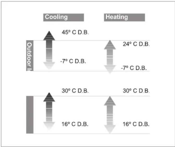
2 Extreme operating conditions
This unit has been designed to operate within the range of temperatures indicated on Figure 2.1. Ensure that these ranges are not exceeded.
bar
| Condition | Temperature Change (°C D.B.) | |---|---| | Outdoor I - Cooling | 45 | | Outdoor I - Heating | 24 | | Outdoor II - Cooling | -7 | | Outdoor II - Heating | -7 | | Outdoor III - Cooling | 30 | | Outdoor III - Heating | 30 | | Outdoor IV - Cooling | 16 | | Outdoor IV - Heating | 16 |Fig. 2.1 Operating ranges of the unit.
Legend
D.B. Temperature measured by dry bulb method
The working capacity of the unit changes depending on the working temperature of the outdoor unit.
3 Identification of the unit
This manual is valid for the Split system series. In order to know the specific model of your unit please refer to the unit nameplates.
The nameplates are located on the outdoor and indoor units.
4 Declaration of conformity
The manufacturer declares that this unit has been designed and constructed in compliance with the standard in force with regard to obtaining the CE Marking.
The appliance type satisfy the essential requirements of the relevant directives and Standards:
2006/95/EEC including amendments:
"Directive on the harmonisation of the laws of Member States relating to electrical equipment designed for use within certain voltage limits"
Designed and built according to European Standards:
EN 60335-1
EN 60335-2-40
EN 50366
2004/108/EEC including amendments:
"Directive on the approximation of the law of the member states relating to electromagnetic compatibility"
Designed and built according to European Standards:
EN 55014-1
EN 55014-2
EN 61000-3-2
EN 61000-3-3
EN 61000-3-11
5 Description of the unit
This unit is comprised of the following elements:
- Indoor unit.
- Outdoor unit.
- Remote controller.
- Connections and accessories.
Figure 5.1 shows the unit components.
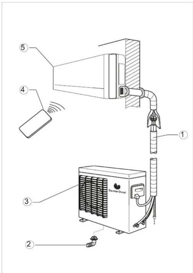
Fig. 5.1 Unit components.
Legend
1 Interconnecting pipework
2 Condensed water drainage pipe
3 Outdoor Unit
4 Remote controller
5 Indoor Unit
5.1 Remote Controller
The remote controller allows the unit's functions to be set as required. In order for the unit to receive the commands properly, the remote control must be pointing directly at the indoor unit, with no obstacles between them whatsoever.
5.2 Features and Benefits
| Technical Specifications | Pictorial Symbol | Description |
| Heat pump |  | The refrigeration system can be reversed. It allows either cooling or heating to the room as desired. |
| Refrigerant R-410A |  | Refrigerant which is free of chlorine, ecological and non ozone depleting with efficiencies greater than R 407 C or than R22, providing far better COP levels. |
| Inverter DC technology Energ |  | greater than conventional inverter systems. |
| Inverter technology |  | Consumption is adapted to the acclimatisation requirement in a regulated way, guaranteeing very low energy costs. The equipment can be operated under extreme temperature conditions (See page 3). |
| Anti-dust filter General filter w |  | nates much of the dirt and dust circulating through the unit |
| Remote controller |  | Remote controller: an infra-red device which allows remote access and control to the units functions |
| Hot start function |  | The indoor unit fan is only operated after the indoor coil reaches temperature. Thereby eliminating cold drafts during the heating cycle |
| Auto restart function After a p |  | get the unit will re-start automatically at the same setting as last set. |
| Valve protection A cover used |  | t the service valves from the effects of bad weather |
| Anti-freeze |  | All heat pump units will tend to freeze up during the colder winter months, the anti-freeze function automatically defrosts the outdoor coil as required |
| Anti-corrosion casing |  | Outdoor unit made of galvanised steel and anti-corrosion materials. Resistant even in highly saline environments. |
Table 5.1 Features and benefits.
OPERATING INSTRUCTIONS
6 Getting started
6.1 Fitting the Remote Controller Batteries
Insert two batteries (2 No. size AAA), as described below (see Figure 6.1).
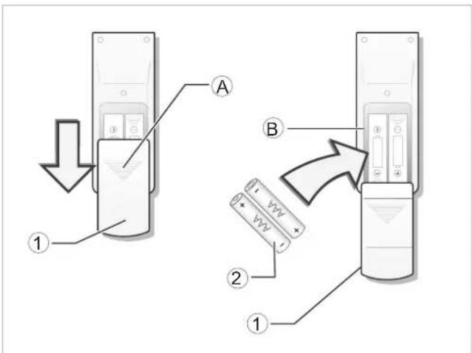
Fig. 6.1 Fitting the remote controller batteries.
Legend
1 Battery lid
2 Batteries
A Pressure area for opening the lid
B Battery compartment
- Remove the battery lid by pressing gently on zone A and pushing the lid downwards.
- Insert the batteries in the remote control ensuring correct positive and negative polarity (Shown on the battery compartment).
- Put the lid back on.
- Press the ON/OFF button (see Figure 7.1) to check that the batteries are correctly inserted.

NOTE:
If nothing appears on the display after pressing ON/OFF, refit or replace the batteries.
Always replace both batteries at the same time.

NOTE:
If the remote controller does not work correctly during operation, please remove the batteries and reposition after a few minutes.
If the unit is going to be out of use for a long period remove the batteries. If there is anything still showing in display, just press the reset button.

ATTENTION:
Danger of the environmental contamination by not disposing of the batteries properly.
When replacing the remote controller batteries, dispose of batteries in the correct manner.
Never throw away in the rubbish.
6.2 Clock Settings
Use the remote controller buttons to adjust the unit clock the first time the unit is started or after replacing the batteries, see Figure 6.2.
- Press the CLOCK button once.
The hour indicator start to flash on the remote controller display. - Press the + / - buttons to set the desired time:
When pressing the + / - buttons, the time configuration will increase or decrease by 1 minute.
If the + / - buttons are kept pressed, the time will increase or decrease rapidly.
- Press the CLOCK button once.
The hour indicator will stop flashing and the clock will start to operate.
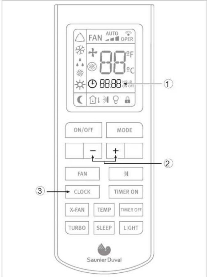
Fig. 6.2 Clock Settings.
Legend
1 Hour indicator
2 +/- buttons
3 CLOCK button
7 Operating instructions
7.1 General Safety Considerations During Use

DANGER of injury and physical damage!
-Do not let children play with the Air to Air heat pump unit. The unit is not designed for use by children or infirm persons without supervision. Do not sit on the outdoor unit under any circumstances.
-Do not put any objects on top of the unit.
-Do not operate the equipment whilst using insecticides or pesticides. These could settle in the unit and harm the health of people with allergies to specific chemical substances.
-Avoid prolonged direct exposure to cooled air or extreme temperatures in the room and do not direct the air flow at people, especially infants, infirm people or old people.
-Do not use this unit to preserve food, art work, precision equipment, plants or animals.
-Do not cover the ventilation grille and do not insert your fingers or other objects in the air inlets and outlets, or between the unit slats whilst the unit is operating. The high speed of the fan can cause injuries.
-Always remember to disconnect the unit before opening the Inlet grille. Never disconnect the unit by pulling the power cord.
-Do not leave the power supply cord in a roll and take care not to damage the power supply cord. After installation the power plug should be easily reached.
-Do not damage any parts of the unit containing refrigerant by piercing the Air to Air heat pumps' tubes with sharp or pointed items, by crushing or twisting any tube or by scraping the coating off the surface. If the refrigerant spurts out and gets into your eyes it may result in serious eye injuries. Seek immediate medical assistance.
-Do not interrupt the operation of the Air to Air heat pump unit by pulling the cord.

DANGER of injury and physical damage!: Danger of fire and explosion.
-Damaged air conditioners should not be put into operation. In case of doubt, consult your supplier.
-The air conditioner must be properly grounded in accordance with specifications.
-Do not place any heat source with a naked flame in the equipment airflow. Do not use sprays or other flammable gases near the Air to Air heat pump equipment. This could cause a fire.
-In the event that any irregularity is detected (such as a burning smell), disconnect the unit from the mains immediately and contact the distributor/installer in order to proceed properly. If you continue to use the unit under these irregular conditions, it could be irrepairably damaged and cause short circuiting or fire.
-If the power supply is damaged, make sure it is replaced by the manufacturer or its service agent or a qualified person.
- If the fuse of the Indoor unit is broken, please change it with type T.3.15A/250V. If the fuse of the Outdoor unit is broken, change it with type T.25A/250V.
-The wiring should be done according to the local wiring standards.
- In order to protect the unit, please turn off the A/C first and at least 30 seconds later, disconnect the power.
-Phone a specialist technician and ensure that preventive measures are implemented to avoid refrigerant gas leaks. Leaking refrigerant of a certain density can cause oxygen deficiency.

DANGER:
Danger electric shock.
Do not handle the equipment with wet or moist hands.

WARNING:
Danger of breakdowns or malfunction.
- Do not place any object on or near to the outdoor unit.
7.2 Identification of functions
7.2.1 Remote Controller Buttons
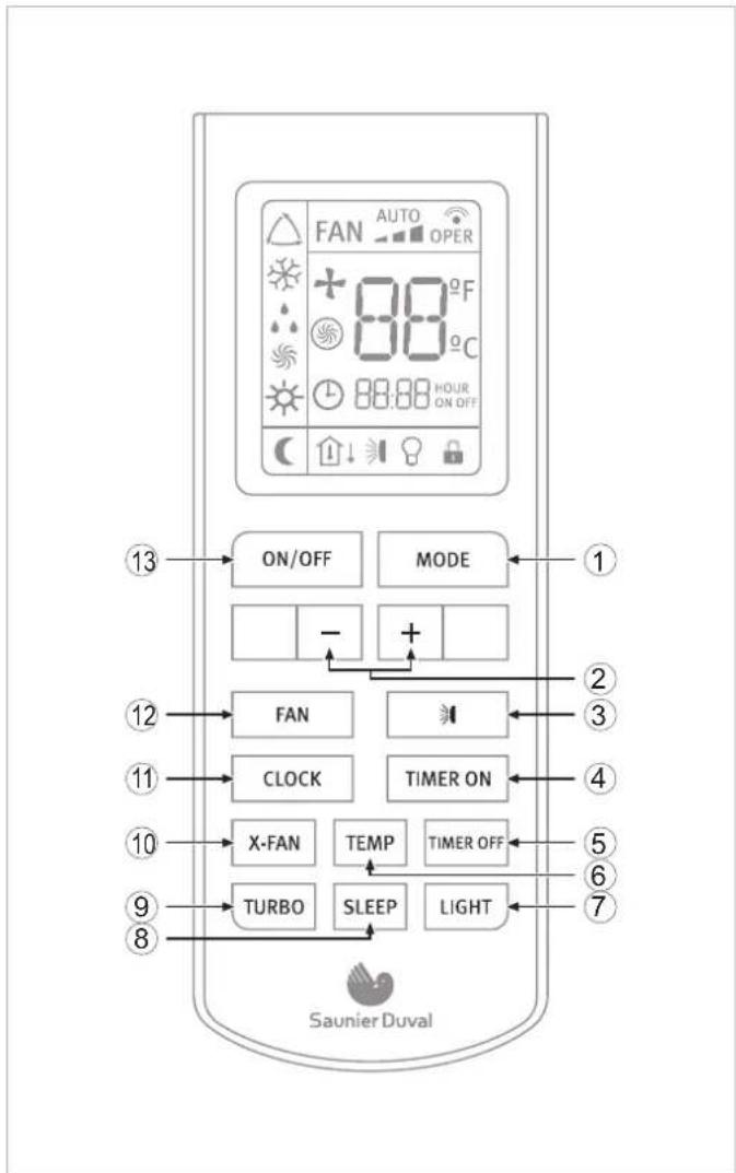
Fig. 7.1 Overview of the buttons.
Legend
1 MODE Button
2 - / + buttons
3 SWING button
4 TIMER ON button
5 TIMER OFF button
6 TEMP button
7 LIGHT button
8 SLEEP button
9 TURBO button
10 X-FAN button
11 CLOCK button
12 FAN button
13 ON/OFF button
7.2.2 Display Indicators

Fig. 7.2 Overview of the display.
Legend
1 FAN SPEED indicator
2 TRANSMISSION indicator
3 X-FAN indicator
4 TEMPERATURE indicator
5 TURBO indicator
6 TIMER indicator
7 LOCK indicator
8 LIGHT indicator
9 SWING indicator
10 "TEMP" indicator
11 SLEEP indicator
12 HEAT MODE indicator
13 FAN MODE indicator
14 DRY MODE indicator
15 COOL MODE indicator
16 AUTO MODE indicator
7.3 Advice on how to use the remote controller
Follow the recommendations below as to how to use the remote controller:
- When in use, direct the head of the signal transmitter directly to the indoor unit receiver.
- Keep the distance between the transmitter and the receiver within 7 m.
- Avoid obstacles between the transmitter and the receiver.
- If experiencing difficulties with the remote control communicating with the indoor unit, reduce the distance between the remote controller and the indoor unit.
- Do not drop, throw or hit the remote controller.
7.3.1 Remote controller lock
In order to lock the buttons and display of the remote controller device:
- Press and hold the - & + buttons, at the same time for over two seconds.
The rest of the buttons are deactivated.
The lock status indicator appears.
In order to deactivate the lock:
- Press and hold the - & + buttons, at the same time again.
The rest of the buttons are activated.
The lock status indicator disappears.
7.3.2 Light function
Press the LIGHT button for less than 2 seconds to light the display of the Indoor Unit. To switch the display back off, press the LIGHT button for less than 2 seconds once again.
7.4 Switching the unit on and off
In order to switch the unit on:
- Press the ON button on the remote controller; the unit will start to operate.
In order to switch the unit off:
- Press the OFF button on the remote controller; the unit will stop.
7.5 Selection of the operation mode
7.5.1 Automatic mode (AUTO)
In automatic mode (AUTO) the Air to Air heat pump unit automatically selects the cooling (COOL) or heating (HEAT) mode in accordance with the actual ambient temperature.
- In COOL mode the set room temperature is 25^ C. Above this room temperature the unit will operate in COOL mode.
- In HEAT mode the set room temperature is 20^ C. Below this room temperature the unit will operate in HEAT mode.
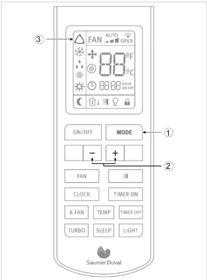
Fig. 7.3 Automatic mode selection.
Legend
1 MODE button
2 - / + button
3 AUTO mode indicator
In order to activate:
With the unit switched on (see section 7.4):
- Press the MODE button.
The different operation modes are displayed.
AUTO

COOL

DRY

FAN ONLY

HEAT
Fig. 7.4 Operation modes.
- Select the automatic operation mode (AUTO).
- Press the TEMP / TIME buttons to select the temperature setting.
When pressing the - / + buttons, the temperature configuration will increase or decrease by 1°C.
When the fan is configured in AUTO mode, the Air to Air heat pump unit automatically sets the fan speed in accordance with the actual ambient temperature.
7.5.2 Cooling mode (COOL)
In cooling mode (COOL), the Air to Air heat pump unit only allows cooling.

NOTE:
In cooling mode it is recommendable to direct the front louvres horizontally.
EN
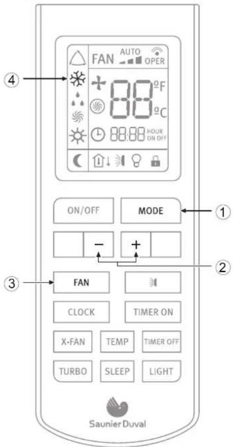
Fig. 7.5 Cooling mode selection.
Legend
1 MODE button
2 - / + button
3 FAN button
4 COOL mode indicator
In order to activate:
With the unit switched on (see section 7.4):
- Press the MODE button.
The different operation modes are displayed.
AUTO

COOL

DRY

FAN ONLY

HEAT
Fig. 7.6 Operation modes.
- Select the cooling operation mode (COOL).
- Press the - / + buttons to select the temperature setting.
When pressing the -/+ buttons, the temperature configuration will increase or decrease by 1°C.
- Press the FAN button to select the fan speed.
Each time the FAN button is pressed, the fan speed will be modified as shown in Figure 7.7.


Fig. 7.7 Fan speed.

NOTE:
In cooling mode, prolonged use of the unit under conditions of considerable air humidity can cause drops of water to fall from the outlet louvres.
7.5.3 Dehumidifying Mode (DRY)
In dehumidifying mode (DRY), the Air to Air heat pump unit operates by reducing the humidity from the atmosphere.
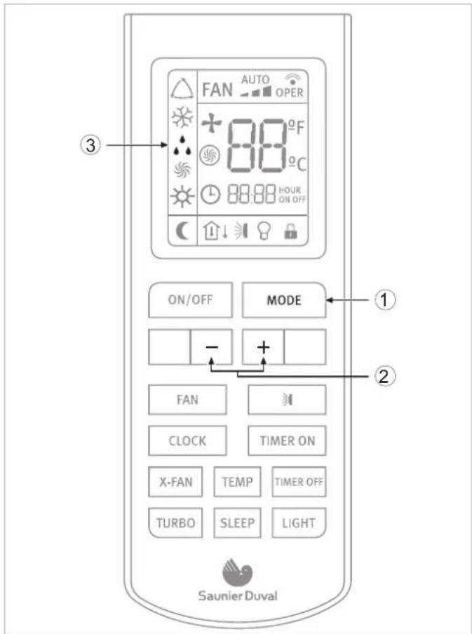
Fig. 7.8 Dehumidifying mode selection.
Legend
1 MODE button
2 DRY mode indicator
3 TEMP / TIME buttons
In order to activate:
With the unit connected (see section 7.4):
- Press the MODE button.
The different operation modes are displayed.

Fig. 7.9 Operation modes.
- Select the dehumidifying mode (DRY).
- Press the - / + buttons to select the temperature setting.
When pressing the - / + buttons, the temperature configuration will increase or decrease by 1°C.
When the fan is set to DRY mode, the air conditioner selects the low fan speed to make the most effective mode.

NOTE:
In dehumidifying mode, prolonged use of the unit under conditions of considerable air humidity can cause drops of water to fall on the outlet louvres.
7.5.4 Fan mode (FAN)
In fan mode (FAN) the SLEEP function is disabled.
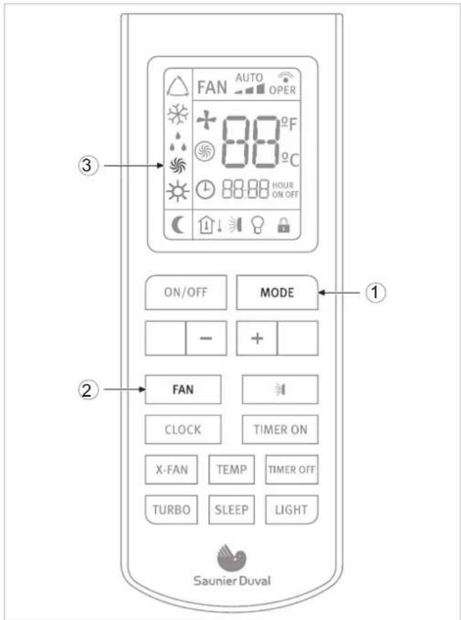
Fig. 7.10 Fan selection mode.
Legend
1 MODE button
2 FAN mode indicator
3 FAN button
In order to activate the fan mode (FAN):
With the unit switched on (see section 7.4):
- Press the MODE button.
The different operation modes are displayed.

Fig. 7.11 Operation modes.
- Select the fan operation mode (FAN).
- Press the FAN button to select the fan speed.
Each time the FAN button is pressed, the fan speed will be modified as shown in Figure 7.12.
Fig. 7.12 Fan speed.
7.5.5 Heating mode (HEAT)
In heating mode, the Air to Air heat pump only allows heating.
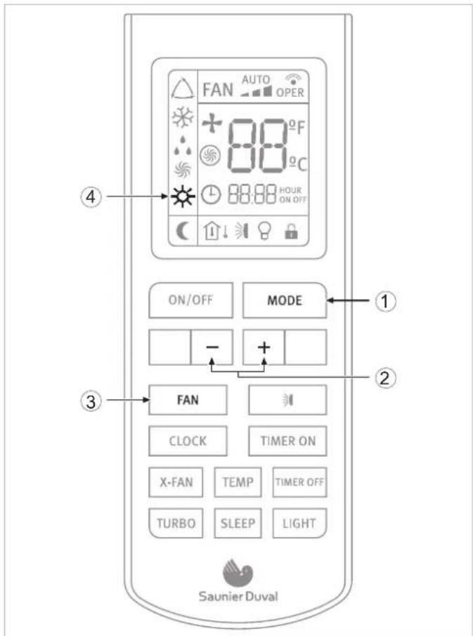
Fig. 7.13 Heating mode selection.
Legend
1 MODE button
2 - / + button
3 FAN button
4 HEAT mode indicator
In order to activate:
With the unit switched on (see section 7.4):
- Press the MODE button.
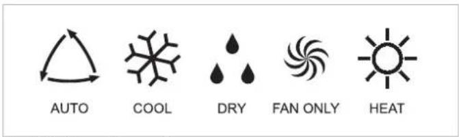
Fig. 7.14 Operation modes.
- Select the heating operation mode (HEAT).
- Press the - / + buttons to select the temperature setting.
When pressing the - / + buttons, the temperature configuration will increase or decrease by 1°C.
- Press the FAN button to select the fan speed.
Each time the FAN button is pressed, the fan speed will be modified as shown in Figure 7.15.

Fig. 7.15 Fan speed.

NOTE:
When the unit stops the compressor by thermostat, or when the defrost function is performing, the indoor units fan will remain stopped to prevent cold air expelled.
7.6 Setting the direction of the airflow
The direction of the airflow can be set in vertical direction on HEAT mode, and in horizontal direction on COOL mode.

DANGER OF INJURY AND PHYSICAL DAMAGE!:
Avoid direct body contact with the powerful airflows. Do not expose animals and plants directly to the airflow. They could suffer damage.

WARNING:
Danger of breakdowns or malfunction. Do not open the outlet louvres manually.

NOTE:
If the louvre does not work correctly, stop the unit for one minute and restart it carrying out the settings required with the remote controller.
7.7 Special function selection
7.7.1 Sleep function
The COOL and HEAT modes can be set during the nighttime hours to avoid an excessive increase or decrease in the temperature.
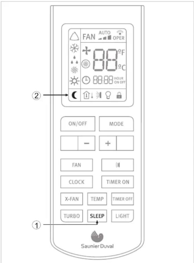
Fig. 7.16 Selection of SLEEP function.
Legend
1 SLEEP button
2 SLEEP function indicator
In order to activate:
- Select the desired operation mode (see section 7.5).
- Press the SLEEP button.
SLEEP function in COOL mode
The ambient temperature is increased by 1 °C per hour with respect to the set temperature during the first two hours. This new temperature is then maintained for the next 5 hours, then gradually decreased again over the next two hours to reach the original set temperature.
SLEEP function in HEAT mode
The ambient temperature is decreased by 1 °C every hour with respect to the set temperature during the first two hours. This new temperature is then maintained for the next 5 hours, then gradually increased again over the next two hours to reach the original set temperature.

NOTE: While the SLEEP function is activated, the fan operates at low speed.
7.7.2 Timer On/Off function (Switch On/Switch Off using timer)
The unit can be switched on/switch off using the timer.
Fig. 7.17 Selection of TIMER function.
Legend
1 TIMER ON/OFF function indicator
2 - / + buttons (increase/decrease)
3 TIMER ON button
4 TIMER OFF button
In order to program a switch on time for the unit:
- With the unit switched off, press the TIMER ON button. The TIMER ON indicator starts to blink. Set the desired starting time by pressing the - / + buttons. Press the TIMER ON button again to confirm the desired starting time.
In order to program a switch off time for of the unit: - With the unit switched on, press the TIMER OFF. The TIMER OFF indicator starts to blink. Set the desired switch off time of the unit by pressing the - / + buttons. Press the TIMER OFF button again to confirm the desired switch off time.
In order to cancel: - Press the TIMER ON or TIMER OFF button again.

NOTE:
REPEAT function available by default. If the program is not canceled, it will be repeated daily.

NOTE:
Correctly set the clock before operating the timer.

NOTE:
Restart the time configuration after replacing the batteries or after a possible power failure.
7.7.3 Turbo function
Use the TURBO function when you need fast cooling (COOL MODE) or fast heating (HEAT MODE).
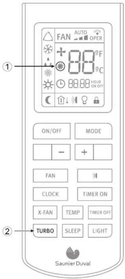
Fig. 7.18 TURBO function selection.
Legend
1 TURBO icon
2 TURBO button
To activate or deactivate the TURBO function:
- Press the TURBO button for less than two seconds.
7.7.4 X-fan function
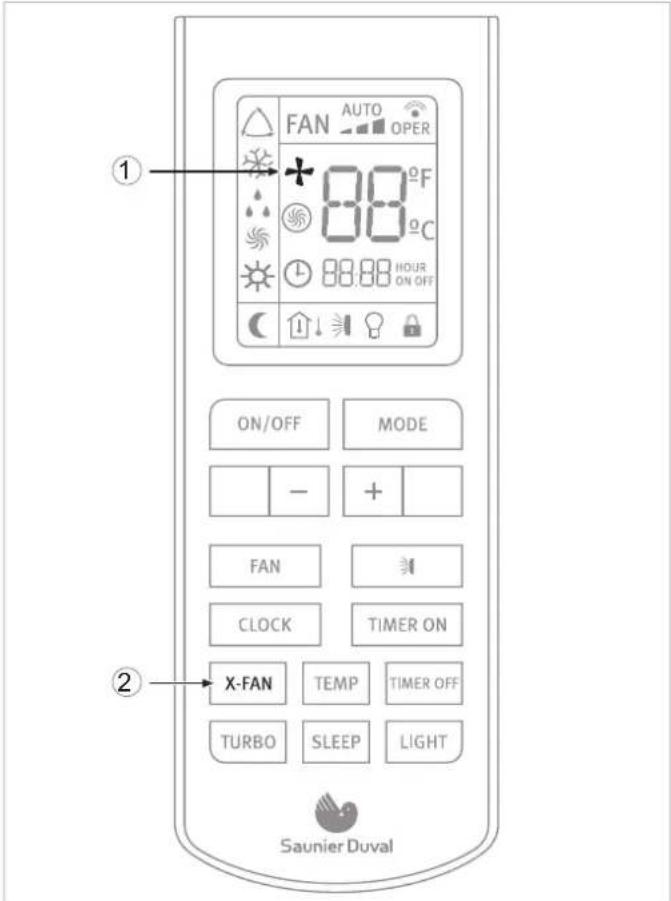
Fig. 7.19 X-FAN function selection.
Legend
1 X-FAN icon
2 X-FAN button
When pressing the "X-Fan" button in COOL or DRY mode, the indicator in the remote control's display will light up and the indoor unit's fan will remain functioning for approximately 2 minutes, even after having switched the appliance off or having it programmed for the switch off. Once this period of time passes, the unit will automatically turn off, and the indoor unit's COOL mode indicator will flicker every 10 seconds.
This causes the humidity in the indoor unit to be expelled, keeping it dry and preventing it's components from going rusty and bacteria from appearing.
The X-Fan function is not available in AUTO, FAN or HEAT mode.
7.7.5 Temp function
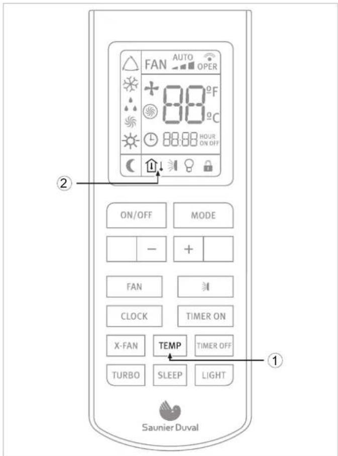
Fig. 7.20 TEMP function selection.
Legend
1 TEMP button
2 TEMP indicator
This function displays the indoor setting temperature and indoor ambient temperature on the Indoor Unit display.
Pressing the TEMP button will display:
| [40C8] | Set temperature |
| [2X60] | Indoor ambient temperature |
 | Outdoor ambient temperature(Not available for this model) |
7.8 Indicators of the indoor unit
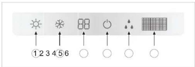
Fig. 7.21 Overview of the display in the indoor unit.
Legend
1 HEATING indicator
2 COOLING indicator
3 TEMPERATURE indicator
4 ON-OFF indicator
5 DEFROST indicator
6 Infra-red signal receiver
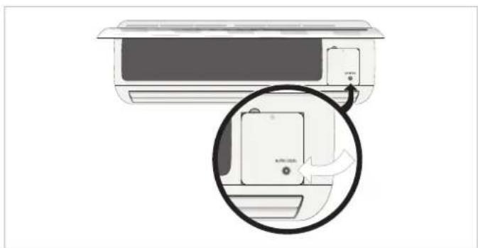
7.9 Emergency operation
Only use this function when the remote controller is broken or has been mislaid.
In order to activate:
- Press the emergency operation switch.
- A beeping noise is heard which indicates that the function has been put into operation.
natural_image
Illustration of a small air conditioner unit with a magnified inset showing the device's internal structure (no text or symbols)Fig 7.22 Emergency operation/operation test switch.
Operating sequence:
- With the first press of the button, the unit enters into Auto mode.
- With the second press of the button, the unit switches off.

NOTE:
During Emergency Operation, the unit operates in AUTO mode by default.
MAINTENANCE
8 Advice for saving energy
8.1 Suitable room temperature
Set the room temperature to an appropriate value to ensure physical wellbeing, comfort and to comply with the legal standards if required. Each degree above this value significantly increases the energy consumption.
The temperature must also be suitable for the specific use being made of the room: the temperature of empty rooms and bedrooms does not have to be the same as the main living room.
8.2 Eliminating heat or cold sources
In the event that there are any heat (in cooling mode) or cold (in heating mode) sources that could be eliminated please do so (e.g. a window or a door which are not properly closed). This will ensure that the unit consumes less energy.
8.3 Operation in heating mode (heat pump)
Your unit, when operating in heating mode, acts as a heat pump, i.e. it takes heat from the outside (via the outdoor unit) and releases it inside (via the indoor unit). Nevertheless, a conventional heating system produces heat purely by consuming energy. Therefore, heating a room using a heat pump is far more economical than using conventional heating (radiators, heaters, boilers, etc.).
8.4 Ambient temperature when absent
During heating mode, an economic saving is made by keeping the room temperature at approx. 5^ C lower than the normal temperature. A reduction which exceeds these 5^ C does not provide any further energy savings since greater heating power is required for consecutive periods of operation in normal operating conditions.
It is only worth reducing the temperature even further in the event of prolonged absences, e.g. during holidays.
During winter when protection against freezing must be guaranteed.
8.5 Uniform heating
Often in a house only the one room is heated. In addition to the surfaces which form the perimeter of this area, i.e. the walls, doors, windows, ceiling and floor, the adjacent rooms are cooler than the room temperature therefore: thermal energy is unintentionally lost. It is therefore difficult to adequately heat the room and an unpleasant feeling of cold is felt (the same occurs when leaving open doors which separate heated areas and unheated areas in a limited way).
This is false economy: the heating is on and, nevertheless, the ambient temperature is not pleasant. Greater comfort and a more reasonable operating mode are achieved by heating all the rooms in a house uniformly, taking into account the use being made of each room (the temperature of empty rooms and bedrooms does not have to be the same as the main room, as long as they are not significantly cooler than the main room).
8.6 Reduction in consumption during night hours (Sleep function)
Your unit has a SLEEP function which allows the temperature to be modified automatically in relation to the predetermined values (in heating mode the temperature decreases slightly; in cooling mode the temperature increases slightly) during sleep setting period. Thus, apart from greater comfort being provided there is also a reduction in the electricity consumption. For more details regarding the SLEEP function, please consult section 7.7.1).
8.7 Reduction in consumption with programmed operating time (Timer function)
By using the TIMER function you can adjust the operation start time of your unit. Therefore, it is possible to programme the operation of your unit to make it function only when required and thus achieve more economic operation.
8.8 Appropriate maintenance of the unit
A unit in perfect condition operates efficiently, taking maximum advantage of the energy it consumes. Ensure that your unit is correctly serviced (for more details please consult section 10). In particular, make sure that the filters are kept clean and that the air inlets and outlets are not obstructed either on the indoor or outdoor unit. Failure to do so will lead to an increase in energy consumption.
9 Troubleshooting
The table below describes a selection of problems with their possible causes and solutions, see Table 9.1.
If these solutions do not solve the problem contact your usual installer or call your nearest Saunier Duval office.
| SYMPTOMS POSSIBLE CAUSES POSSIBLE SOLUTION | ||
| The system does not restart immediately When unit is stopped, it won't restart until 3 minutes have elapsed to protect the system | Wait 3 minutes before starting the unit again | |
| When power is disconnected and reconnected again, the protection circuit will work for three minutes to protect the air to air heat pump unit | ||
| The system does not work at all (the ventilation does not start) | The power lead is not connected correctly Connect the power lead correctly | |
| Power supply cut Reconnect the power supply | ||
| The fuse has blown Replace the fuse. Only use the right fuses for each model. Do not use wire or other material to replace the fuse. Fires could be caused | ||
| Insufficient cooling or heating Doors and/or windows open Close the doors and/or windows | ||
| Heat source nearby (e.g. lots of people in the room) | ||
| The thermostat is set to an excessively high temperature in cooling mode or excessively low temperature in heating mode | ||
| Obstacle in front of the air inlet or outlet Remove the obstacle to allow the air to circulate properly | ||
| The ambient temperature has not reached the designated level | ||
| Dirty or blocked air filter Clean the air filter (the air filter should be cleaned every 15 days) | ||
| Is there any direct sunlight through the window during the cooling operation? | ||
| Noise is heard During unit operation or when stopping the unit a gurgling noise may be heard. This noise is more audible the first 2-3 minutes of operation | This is normal in an Air to Air heat pump unit. The noise is caused by the refrigerant flowing in the system). | |
| A cracking noise is heard during operation This is normal in an Air to Air heat pump unit. The noise is caused by the casing expanding or shrinking due to the temperature changes | ||
| If the noise is loud and comes from the louvers during the unit operation, the air filters may be too dirty | ||
| Smells are generated This is because the system circulates smells from the indoor surrounding (furniture, cigarettes) | This situation does not require any action | |
| Mist or steam come are blown out from the unit During COOL mode or DRY mode operation, the indoor unit may blow some mist. This is due to the sudden cooling of the indoor air. | This situation does not require any action | |
Table 9.1 Troubleshooting.
10 Maintenance

DANGER:
Danger of electric shock.
Disconnect the unit and isolate the mains supply before proceeding to carry out maintenance on the unit.
Ensure the the mains supply cannot be reconnected inadvertently. This will prevent injuries..

DANGER:
Danger of electric shock.
Do not clean the unit with water.

WARNING:
Danger of breakdowns or malfunction.
Do not use gasoline, benzine, thinner or cleansers when cleaning the unit. It may damage the coating of the unit.

WARNING:
Hot water over 40^ C may cause discoloring or deformation.
10.1 Cleaning the remote controller
- Wipe the controller with a dry cloth. Do not use water to clean the remote controller.
- Do not use glass cleaners or chemical cloths.
10.2 Cleaning the indoor unit
- Wipe the outer part of the unit with a soft and dry cloth.
- For difficult stains, use a neutral detergent diluted in water. Eliminate the excess of water form the cloth before wiping. Leave the unit clean from any detergent.
10.3 Cleaning the air filters

The air filter traps the dust circulated from the room into the indoor unit.
If the filter becomes blocked, the air conditioner's efficiency will be reduced, the compressor could be damaged and the indoor unit's heat exchanger coil could freeze up.
Clean the air filter regularly to prevent this from happening. In order to do so:
- Remove the air filters by slightly pushing up the center tab until it is released from the stopper and remove the filter downwards.
- Clean the filter removing the dust or the dirt using a vacuum cleaner or cleaning them with cold water.
- Ensure that the filters are dried completely (dry in the shade) before putting them back into the unit. The activated carbon filters (where fitted) can be reactivated by placing in direct sunlight. If strange odours are still smelt replace with new. If strong odours continue to be a problem, contact your after sales service provider to fully clean the unit.
- Attach the filter correctly and make sure it is completely fixed behind the stopper. If the right and left filters are not properly fixed, this could cause a malfunction.

WARNING:
Danger of breakdowns or malfunction.
Do not attach perfume systems, anti-odour systems etc. in the filter or in the inside air return.
This can damage and soil the heat exchanger coil. If necessary, install these systems at the unit's outlet point and ensure they only run when the fan is on.
10.4 Cleaning the Outdoor Unit

WARNING:
Always use suitable personal protection equipment (helmet, gloves, safety boots and protective glasses).
- Wipe the outer part of the unit with a dry cloth.
• Occasionally remove dust and leaves from the inlet surface. - Periodically clean the heat exchanger fins with a soft brush when the unit is located in a dusty environment.
• Occasionally check the base of the outdoor unit.

DANGER OF INJURY AND PHYSICAL DAMAGE!
A damaged or deteriorated base could make the unit unstable and potentially cause physical or material damage.

DANGER OF INJURY AND PHYSICAL DAMAGE!
Except for servicing or replacement, do not dismantle the outdoor unit outlet. Exposing the fan can be very dangerous.

NOTE:
We advise you to contact a reliable air conditioner specialist or the Saunier Duval Group Technical Service to contract a preventative maintenance service. This will help to prolong the life of your equipment and improve its performance.
11 Storage over a prolonged period
If you do not intend to use the unit over a period of time:
- Put the fan into operation for two or three hours at a temperature of 30^ , in COOL mode and at High Speed fan in order to prevent mold or smells.
- Stop the unit and disconnect the mains power supply.
- Clean the air filters.
- Clean the Outdoor unit.
- Remove the batteries from the remote controller.
Before turning the unit back on:
- Replace the remote controller batteries.
- Be sure to attach both right and left filters prior operation.
- Check that the air filters are not blocked.
- Check that the air outlet and inlet are not blocked.
- Re-connect the mains power and run and test the system in all modes. If any strange noise or performance is experienced contact your after sales service provider.

DANGER OF INJURY AND PHYSICAL DAMAGE!
In the event that the equipment is removed and reinstalled at a later date, ensure that the equipment is properly installed by personnel with the appropriate qualifications (see manual for installer). Otherwise water leakage, refrigerant leakage, short circuiting or even fire could be caused.
12 Product decommissioning

DANGER of injury and physical damage!
When disposing of the product, ensure that is done safely and in accordance with local by-laws and regulations. In order to do so follow the steps described in the installation manual in reverse order and use the necessary tools and protection equipment. Ensure that the disassembly is carried out by qualified, technically competent individuals.

WARNING:
Danger of environmental contamination when disposing of the unit. To avoid this, follow the instructions described in this section.

WARNING:
Air conditiong systems contain refrigerants which require specialised waste disposal. The valuable materials contained in an air conditioner can be recycled.
natural_image
Symbol of a trash bin crossed with no text or numbers, representing waste sorting or disposal (no text present)Fig. 12.1 Recycling symbol.
Your product is marked with the recycling symbol (see Figure 12.1), which means that the following must be taken into account during the disposal:
- Do not mix the unit with other domestic, unclassified waste.
- Dispose of the equipment in accordance with the relevant local and national standards, correctly and in an environmentally-friendly way.
- Hand in the unit to a waste management company that is authorised by the local authorities to transport it to a proper treatment plant.
- If the product is being replaced with a new product destined for the same use, hand in the old product to the distributor of the new unit for waste management as appropriate.
- Contact local authorities for more information.
Manual de Usuario
MURALES
SDH 17-025 NW
SDH 17-035 NW
SDH 17-050 NW
SDH 17-065 NW
LISTADO DE EMBALAJE
Danger electric shock.

¡ATENCIÓN!:
Potentially dangerous situation for the product and the environment.

NOTA:
natural_image
Illustration of a wall-mounted air conditioner unit with a magnified inset showing the device's internal structure (no text or symbols)natural_image
Symbol of a trash bin with no text or numbers, crossed by diagonal lines and a solid black rectangle below (no text or symbols present)Fig. 6.1 Inserimento delle batterie del telecomando.
Legenda
1 Coperchio batterie
2 Batterie
A Area da premere per l'apertura del coperchio
B Compartimento batterie
natural_image
Diagram of a KU-1000 air conditioner unit with a magnified inset showing the internal component (no text or symbols present)natural_image
Symbol of a trash bin with crossed lines indicating no waste or restriction, and a solid black rectangle below (no text or labels)7.5.4 Tryb wentylatora (FAN)
natural_image
Illustration of a wall-mounted air conditioner unit with a magnified inset showing the device's internal structure (no text or symbols)natural_image
Symbol of a trash bin crossed with no text or numbers, representing waste sorting or disposal (no text present)• 2006/95/EEC incluindo as emendas:
• 2004/108/EEC incluindo as emendas:
6.1 Colocar as pilhas do controlo remoto
natural_image
Illustration of a wall-mounted air conditioner unit with a magnified inset showing the device's internal structure (no text or symbols)natural_image
Symbol of a trash bin crossed with no text or numbers, representing waste sorting or disposal (no text present)Fig. 12.1 Símbolo de reciclagem.
Saunier Duval reserves the right to modify specifications without prior notice
- PACKLISTE
- CONTENTS
- INTRODUCTION
- OPERATING INSTRUCTIONS
- MAINTENANCE
- Advice for saving energy....19
- Troubleshooting 20
- Maintenance ....21
- Your safety
- Symbols used
- Correct use of the unit
- Extreme operating conditions
- Identification of the unit
- Declaration of conformity
- Description of the unit
- Legend
- Remote Controller
- Features and Benefits
- Getting started
- Fitting the Remote Controller Batteries
- NOTE:
- ATTENTION:
- Clock Settings
- Operating instructions
- General Safety Considerations During Use
- DANGER of injury and physical damage!
- DANGER of injury and physical damage!: Danger of fire and explosion.
- DANGER:
- WARNING:
- Identification of functions
- Remote Controller Buttons
- Display Indicators
- Advice on how to use the remote controller
- Remote controller lock
- Light function
- Switching the unit on and off
- Selection of the operation mode
- Automatic mode (AUTO)
- Cooling mode (COOL)
- EN
- Dehumidifying Mode (DRY)
- Fan mode (FAN)
- Heating mode (HEAT)
- Setting the direction of the airflow
- DANGER OF INJURY AND PHYSICAL DAMAGE!:
- Special function selection
- Sleep function
- SLEEP function in COOL mode
- SLEEP function in HEAT mode
- Timer On/Off function (Switch On/Switch Off using timer)
- Turbo function
- Temp function
- Indicators of the indoor unit
- Emergency operation
- Advice for saving energy
- Suitable room temperature
- Eliminating heat or cold sources
- Operation in heating mode (heat pump)
- Ambient temperature when absent
- Uniform heating
- Reduction in consumption during night hours (Sleep function)
- Reduction in consumption with programmed operating time (Timer function)
- Appropriate maintenance of the unit
- Troubleshooting
- Maintenance
- Cleaning the remote controller
- Cleaning the indoor unit
- Cleaning the air filters
- Cleaning the Outdoor Unit
- Storage over a prolonged period
- Product decommissioning
- LISTADO DE EMBALAJE
- Legenda
- Tryb wentylatora (FAN)
- Colocar as pilhas do controlo remoto
Brand : SAUNIER DUVAL
Model : SDH 17-050 NW
Category : Air-conditioner