YT9071A - Brush cutter Cotech - Free user manual and instructions
Find the device manual for free YT9071A Cotech in PDF.


| Product Type | Brush cutter (string trimmer) |
| Model | YT9071A |
| Brand | Cotech |
| Engine Type | 2-stroke, air-cooled |
| Displacement | 31 cc |
| Power Output | 1.2 kW |
| Cutting Width | 41 cm (16 in) |
| Cutting Line Diameter | 2.4 mm |
| Fuel Tank Capacity | 0.6 L |
| Oil Fuel Ratio | 40:1 (petrol:2-stroke oil) |
| Weight (without fuel) | 6.2 kg |
| Shaft Type | Straight shaft |
| Handle Type | Loop handle with anti-vibration |
| Cutting Head | Bump-feed trimmer head |
| Safety Features | Stop switch, protective guard, shoulder strap included |
| Maintenance | Clean air filter regularly, sharpen blade as needed |
| Spare Parts | Spool, blade, air filter, spark plug available |
| Warranty | 2 years (standard) |
Frequently Asked Questions - YT9071A Cotech
User questions about YT9071A Cotech
0 question about this device. Answer the ones you know or ask your own.
Ask a new question about this device
Download the instructions for your Brush cutter in PDF format for free! Find your manual YT9071A - Cotech and take your electronic device back in hand. On this page are published all the documents necessary for the use of your device. YT9071A by Cotech.
USER MANUAL YT9071A Cotech
Brush Cutter/Grass Trimmer
Read the entire instruction manual carefully and make sure that you fully understand it before you use the equipment. Keep the manual for future reference.
Viktig information:
Original instructions
Bruksanvisning i original
Brush Cutter/Grass Trimmer
ART.NO 40-7947 MODEL YT9071A
Please read the entire instruction manual before using the product and save it for future reference.
We reserve the right for any errors in text or images and any necessary changes made to technical data.
If you have any questions regarding technical problems please contact Customer Services.
1. Safety
Warning: Children, pets and onlookers should keep at least 15 metres away from the brush cutter/grass trimmer when it is being used. Turn it off immediately if anyone comes closer.
1.1 Product safety symbols and their meaning

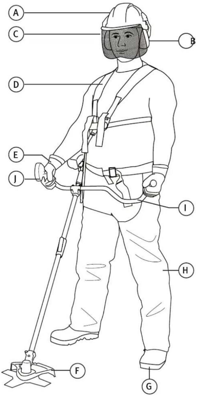
Wear protective head gear, protective eyewear/visor and ear defenders.
Wear protective gloves.
Wear safety footwear.
Read the instruction manual carefully and make sure that you understand its contents before you use the product. Save the manual for future reference.
Stones and other debris can be ejected by the trimmer.
Do not permit anyone else to come close to the trimmer when it is in use.
Children, pets and bystanders should keep a distance of at least 15 metres away from the trimmer when it is being used.
Do not touch the blade whilst it is rotating.
Only accessories approved for speeds up to 8500 rpm should be used.
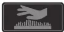
Caution! Hot surface. Do not touch.
1.2 Guidelines for safe use
N.B. Switch off the engine before all servicing, adjusting and cleaning of the brush cutter/grass trimmer.
- Wear protective footwear, tight-fitting clothes and safety glasses/visor, ear defenders and a helmet.
- Never use the brush cutter/grass trimmer if you are tired, sick, upset or under the influence of medication which causes drowsiness, alcohol or drugs.
-
Always be careful when handling fuel. Open the fuel tank carefully and release any pressure which might have built up in the tank. Wipe off any spilt fuel and move the brush cutter/grass trimmer at least 3 metres away from the refuelling location before starting it.
3a. Remove any sources of ignition, sparks, open flames, smoking, etc. from places where the fuel is mixed, used or stored.
3b. Do not smoke while fuelling or using the brush cutter/grass trimmer. -
Do not permit anyone other than the operator to come close to the brush cutter/grass trimmer when it is being started or used. Children, pets and bystanders should keep a distance of at least 15 metres away from the brush cutter/grass trimmer when it is being used.
-
Always hold both handles of the brush cutter/grass trimmer firmly with your fingers on one side of the handle and thumb on the other side, once the engine is running.
-
Keep all body parts away from the trimmer line or brush cutter blade when the engine is running.
-
Make sure that the trimmer line or cutter blade is not in contact with any object before starting.
-
Only transport the trimmer with the engine switched off.
-
Always inspect the brush cutter/grass trimmer before starting, do not start it if there are worn, damaged or missing parts. Never use the brush cutter/grass trimmer if it is damaged, incorrectly adjusted or incorrectly assembled.
-
All service other than that mentioned in this instruction manual should be carried out by qualified personnel.
-
Switch off the brush cutter/grass trimmer before laying it on the ground.
- Be extra vigilant when cutting small bushes or thick grass, it can get stuck in the trimmer head.
-
Keep the handles clean, dry and free from oil or fuel.
-
Only use the trimmer outdoors or in well ventilated areas. Never start the trimmer in a closed room or building. Exhaust fumes are dangerous to inhale. They contain carbon monoxide.
-
Avoid moving the trimmer head close to small objects which can be thrown about. Check that there are no small stones, shards or glass, etc in the area to be trimmed before starting work.
-
Always stand below the trimmer if you are using it on a slope. NEVER use the trimmer on a slope if there is the slightest risk of you losing your footing, falling or sliding. Keep hold of both handles.
-
Keep the brush cutter/grass trimmer free from grass cuttings and other deposits, particularly the guard, trimmer head and engine.
-
The brush cutter/grass trimmer must only be used by adults who have read the instruction manual.
-
Only use two-stroke engine fuel with a mixture of 2 % good quality two-stroke oil (50:1) intended for air-cooled two-stroke engines. Using petrol without oil mixed in will cause engine damage that is not covered by the guarantee.
-
Do not use the brush cutter/grass trimmer without the silencer or silencer cover.
-
Hold both handles of the brush cutter/grass trimmer firmly, with your fingers on one side of the handle and thumb on the other.
-
The silencer can become very hot. Do not touch it with your hands or other parts of you body.
-
The trimmer head must not be raised during use. The trimmer line can injure the operator, work as close to the ground as possible.
-
The brush cutter/grass trimmer must not be used for any other purpose than for clearing brushwood and trimming lawns and gardens.
-
The brush cutter/grass trimmer must not be used if the guard is damaged or missing.
-
This product must not be altered or used for other tasks, the risk of accidents will increase and the guarantee will not be valid.
-
Do not use the brush cutter/grass trimmer close to flammable gases and liquids; this could cause a fire or an explosion.
1.3 Safety equipment
A. Helmet
B. Ear protectors
C. Visor
D. Harness
E. Gloves
F. Trimmer guard/Blade guard
G. Safety boots
H. Heavy-duty work trousers
I. Anti-vibration handle
J. Throttle with stop switch
2. Contents
- Brush cutter /grass trimmer
- Trimmer guard
- Blade guard
- Bag of assorted fasteners
- Handle with throttle
- Harness
- Trimmer head
- Brush cutter blade
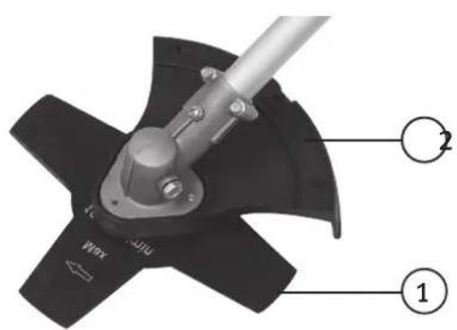
3. Product description
- Brush cutter/grass trimmer with shaft that splits down for ease of transport/storage.
• 35 cc engine, 1.15 kW (1.6 hp) - Primer for easier start
• Double shoulder harness - 230 mm brush blade and trimmer head with semi-automatic line feed
- Weight: 7.4 kg
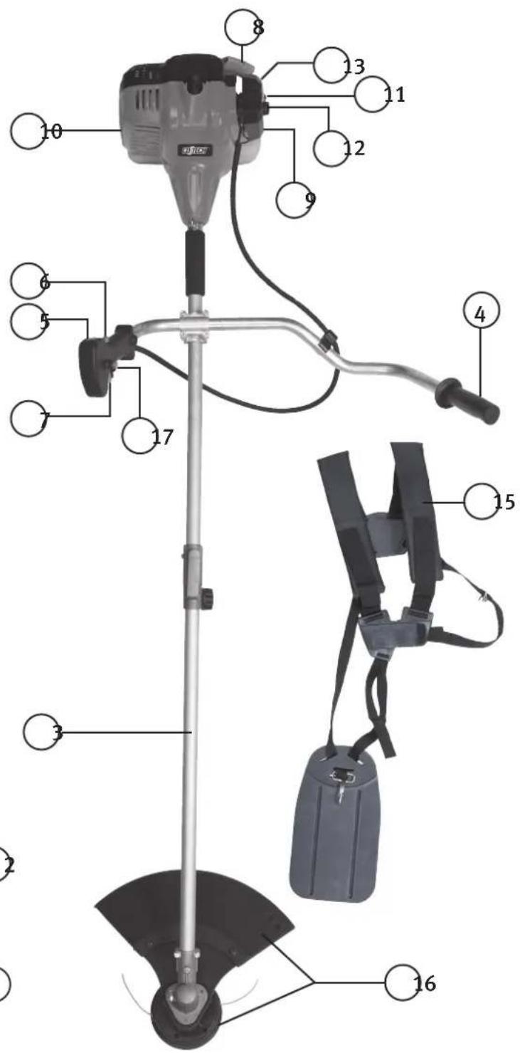
4. Features
- Brush cutter blade
- Blade guard
- Shaft (split, 2-piece)
- Handle
- Ignition switch (on/off)
- Throttle trigger lockout (must be engaged for throttle to work)
- Throttle
- Starter handle
- Primer pump bulb (manual fuel pump to help starting)
- Fuel tank
- Fuel tank cap
- Air filter
- Choke
- Shaft clamp and locking knob
- Harness
- Trimmer head and trimmer guard
- Throttle lock (locks throttle on full power)
5. Assembly
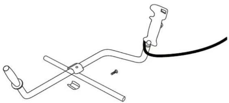
5.1 Assembling the handle
- Remove the screws from the handle bracket attached to the shaft.
- Attach the handle to the bracket so that the right-hand side (with the throttle) is as close to the shaft as possible.
- Loosely screw in the four handle screws.
- Fine-adjustments to the handle position should be made when the rest of the assembly is completed.
natural_image
Technical line drawing of a mechanical clamp or tool with a cable and two clamps (no text or symbols)5.2 Attaching the blade guard/trimmer guard
The guard consists of two parts: blade guard and trimmer guard.
- The inner, blade guard must always be attached when using the brush cutter blade.
- The outer, trimmer guard (together with the inner blade guard) must always be attached when using the trimmer head.
- Attach the blade guard (2) to the bracket using the supplied nuts, bolts and washers.
- Attach the trimmer guard (16) to the blade guard using the supplied nuts, bolts and washers.
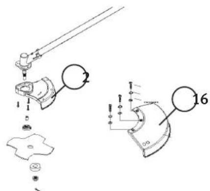
Warning: The trimmer guard must be assembled correctly to protect the operator and to limit the length of the trimmer line, there is a cutter on the guard that cuts the line to the right length.
5.3 Double shoulder harness
Use the harness as follows:
- Put the harness on so that the trimmer hanging clip is on the right-hand side and the quick release tab is on your chest.
- Hold the trimmer on your right-hand side and hook it onto the clip.
- Adjust the harness so that the trimmer is balanced. Adjust the handle if necessary.
- When using the grass trimmer, the harness should be adjusted so that the trimmer head hangs 0–300 mm over the ground.
- When using the brush cutter, the harness should be adjusted so that the brush blade hangs 100–300 mm over the ground.
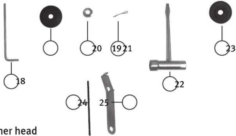
Accessories
- Allen key
- Outer flange washer
- Nut
- Cotter pin
- Spark plug wrench
- Inner flange washer
- Drive shaft locking tool
- Trimmer head spanner
5.4 Attaching the blade/trimmer head
Caution! The brush cutter/grass trimmer must only be used with a nylon trimmer line or a four-bladed brush cutter blade. No other types of cutting attachments may be used.
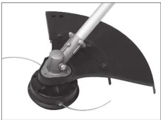
5.5 Attaching the trimmer head
- Push the inner flange washer onto the drive shaft with the flat side facing outwards. Lock the drive shaft by poking the locking tool (24) through the hole in the blade guard (attached under the gearbox) and the hole in the drive shaft.
- Screw the trimmer head on anticlockwise and tighten it.
- Make sure that both the blade guard (inner) and trimmer guard (outer with line cutter) are attached.
5.6 Attaching the brush cutter blade
- Push the inner flange washer onto the drive shaft with the flat side facing outwards. Lock the drive shaft by poking the locking tool (24) through the hole in the blade guard (attached under the gearbox) and the hole in the drive shaft.
- Fit the blade onto the drive shaft so that the hole in the centre of the blade locates on the protruding inner flange washer.
- Hold the blade in place and fit the outer flange washer (with the flat side facing the blade).
- Tighten the nut on the drive shaft using the included spanner.
Note: The nut has a left-hand thread).
- Pass the split pin through the hole in the drive shaft and open the ends to lock the nut.
- Make sure that the blade is centred and screwed on tightly.
- Remove the outer trimmer guard (which the line cutter is attached to). Remember to reattach the trimmer guard if you change back to using the trimmer head.
Caution! It is very important that the brush blade is centred on the inner flange washer; otherwise the blade will vibrate and damage the product and might even cause an injury.
natural_image
Mechanical tool with a black wedge and metal rod, showing a curved mechanical component (no text or symbols visible)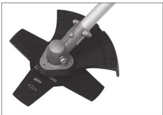
natural_image
Close-up of a mechanical power tool with four blades and a central shaft (no visible text or symbols)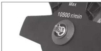
5.7 Assembling the shaft
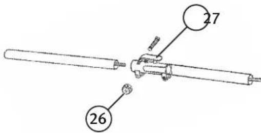
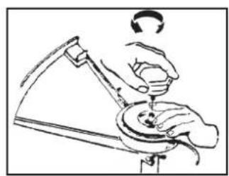
Unscrew the locking knob (26), hold in the release catch (27) and push the bottom half of the shaft into the top half of the shaft. Twist the two halves until the catch locks and then tighten the locking knob.
6. Fuel and Lubrication
We recommend that you use a premixed blend of environmentally friendly 2-stroke engine petrol and 2 % oil.
Caution! Petrol is highly flammable. Avoid smoking close to where fuel is handled, do not cause any sparks, embers or naked flames either. Switch off the brush cutter/grass trimmer and let it cool before refuelling it. Refuel outdoors and always move at least 3 metres away from the refuelling site before starting the trimmer.
Mix petrol (unleaded 95 octane without added ethanol) with a good quality 2-stroke oil intended for air-cooled 2-stroke engines.
Recommended mixture: Petrol/oil 50:1 (2 %).
- The engine is designed to be used with unleaded fuel.
• Use at least an 87 octane rated fuel. - Use unleaded fuel to protect the environment and your health.
- Poor quality fuel or oil can damage seals, fuel pipes or the fuel tank.
6.1 Mixing the fuel
N.B. Be precise with the mixture.
- Measure out the petrol and oil precisely before mixing.
- Pour a small amount of the petrol into a clean fuel can.
- Pour in all of the oil and agitate the fuel can.
- Pour in the rest of the petrol and agitate the fuel can for at least a minute. Certain oils do not mix well; therefore it is important that the fuel can be agitated to mix the oil and petrol. The engine will last longer if the fuel is well mixed. If the fuel is not mixed properly the mixture will be too lean and the engine may be damaged.
- Label the fuel can clearly to avoid the risk of misidentification.
- Fuel containing oil is only intended for 2-stroke engines. Pure petrol is for 4-stroke engines. It is therefore very important to label fuel containers clearly.
N.B. Do not mix too much fuel; it should be used within one month.
Caution! Only use fuel containing oil for 2-stroke engines, using pure petrol without the addition of oil will inevitably cause engine damage which is not covered by the guarantee.
6.2 Filling the fuel tank
- Unscrew and remove the fuel cap.
- Fill with fuel until the tank is roughly 80% full.
- Replace and tighten the fuel cap and wipe up any spilt fuel on or around the grass trimmer.
Caution!
• Refuel outdoors and on the ground.
• Always move at least 3 metres away from the refuelling site before starting the trimmer.
- Switch off the grass trimmer and let it cool before refuelling it. Only refuel when you are sure that the fuel can contains 2-stroke fuel!
7. Starting the Engine
N.B. Pull the starter handle (8) straight out. If you pull at an angle the starter cord will rub on the sleeve and soon wear out. Keep hold of the starting handle after pulling it and allow it to return slowly. Never let go of the starting handle straight after pulling it, it could get tangled or break something on the trimmer.
Caution! Only start the engine outdoors, in a well-ventilated place; exhaust fumes are poisonous.
N.B. See the Troubleshooting section if the trimmer doesn't start after several attempts.
Running in the engine
A new engine should be "run in" by using it at low speed and with low resistance for the first few hours. This will help all the moving parts of the engine to loosen up and mate together better and will ultimately lengthen the useful life of the engine.
After the initial running period the engine can be fully loaded and run at full power. However, do not run the engine at full throttle for long periods at a time.
7.1 Starting the engine from cold
Cut the trimmer line to a length of 13 cm before starting to reduce the load while the trimmer warms up.
- Place the grass trimmer on a hard and level surface.
- Press in the trigger lockout (6) and the trigger (7), then press in the throttle lock (17) on the inside of the handle so that the throttle stays pressed in.
- Switch the ignition switch (5) to I.
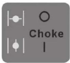
- Lift the choke lever (13) up to activate the choke (close the choke valve).
- Pump the primer pump bulb (9) 10 times (the primer pump bulb is located on the bottom of the carburettor).
- Pull the starter handle until you feel some resistance. Pull the handle 4 or 5 times gently but firmly in quick succession (do not pull the cord the whole way out on the first attempt).
- As soon as the engine has started or fired, the choke lever should be lowered to the "open" position.
- Let the engine run without any load for 10 seconds once started.
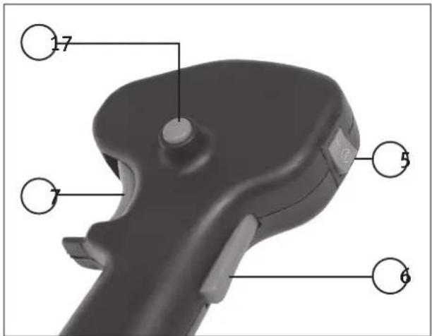
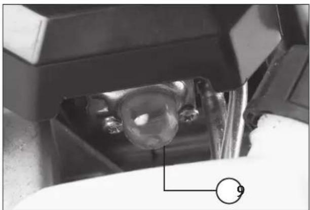
natural_image
Close-up of a mechanical component with a spherical object inserted, showing internal structure and no visible text or symbols.
7.2 Starting a warm engine
- Place the grass trimmer on a hard and level surface.
- Press in the trigger lockout (6) and the trigger (7), then press in the throttle lock (9) on the inside of the handle so that the throttle stays pressed in.
- Switch the ignition switch (5) to I.
- The choke lever (13) should be down in the open position (choke off).
- Pull the starter handle gently until you feel some resistance and then pull it rapidly until the engine starts.
7.3 Switching the engine off
Release the throttle (7) and let the engine revs drop to idling speed, and then push the ignition switch (5) forward to 0.
8. Use
Note!
- Hold the grass trimmer with both hands.
- Depress the throttle and let the engine speed up.
- Hold the trimmer head parallel to the ground and sweep the grass trimmer from side to side whilst slowly walking forwards. Advance more slowly if the going gets heavy.
- Do not move the trimmer head towards you, always work away from yourself.
- Caution! Remove all objects such as cans, bottles and stones from the ground before starting to use the grass trimmer, otherwise they can be thrown about by the trimmer line and cause injury or damage the trimmer.
- Switch off the grass trimmer at once and check it for damage if you notice that something is ejected or if the grass trimmer starts vibrating. Do not operate the grass trimmer if it has been damaged.
- Note! Allow the engine to reach full speed before starting to cut the grass, never try to cut grass/brush at low speed.
- Caution! Never raise the brush blade/trimmer head above knee-height when it is spinning.
- Caution! Never use metal or plastic coated metal trimmer line, this could cause serious accidents.
8.1 Trimming round trees and bushes
Lean the trimmer head forward slightly and start trimming from left to right whilst slowly walking around the tree. Be careful, so the trimmer line doesn't cut the bark of the tree or the plants that you want to keep! If you trim grass close to fences, foundations, rocks, etc; the trimmer line will soon wear out.
8.2 Preparing the ground (removing all vegetation)
- Angle the trimmer head approx. 30 degrees to the left (it is easier if you loosen the loop handle and adjust it).
- Do not do this if there is the slightest risk of something being flung up and injuring people or animals standing within a 30-metre radius.
8.3 Adjusting the trimmer line
Feed out the trimmer line like this:
- Run the engine at full speed whilst carrying out points 2–4.
- Tap the trimmer head on the ground and lift it up again.
- The line will be fed out automatically.
- The line will be cut to the correct length by the cutter under the trimmer guard.
- Switch off the engine and using something like a screwdriver, clean off any grass and debris from around the guard and trimmer head, otherwise it could impair the cooling of the drive shaft.
8.4 Using the 4-tooth brush cutter blade
Use only the supplied 4-tooth brush cutter blade or an identical replacement. A saw-toothed clearing saw blade must not be used.
The 4-tooth blade can be tilted to various angles for cutting brush from around tree trunks.
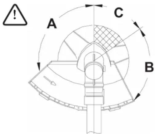
- Normal use: Use the arc of the blade cutting circle labelled "A" for normal brush cutting.
- The arc labelled "B" can also be used if the handles are held firmly.
- Caution! Never use the blade within arc "C", as uncontrolled kickback could occur which could injure any bystanders or animals within the danger zone.
9. Maintenance
Warning: Disconnect the sparkplug lead before carrying out any maintenance.
- Lubricate the pivot after every 25 hours of use:
- Loosen the head of the bolt on the side of the gearbox and smear the pivot with some high temperature grease.
- Wipe off any excess grease.
- Tighten the bolt.
- Clean the cooling fins regularly, so the engine is properly cooled.
9.1 Changing the trimmer line
-
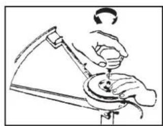
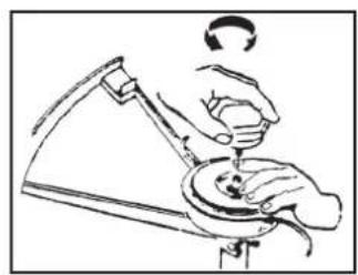
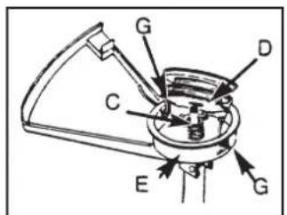
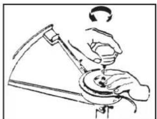
Turn the locking cap (A) clockwise and remove it either by hand or using the supplied spanner.
-
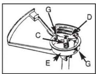
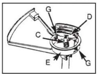
Remove the spool (B) and the spring (C) from the spindle (D).
-
Remove the existing trimmer line (H).
-
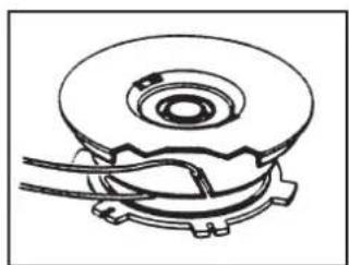
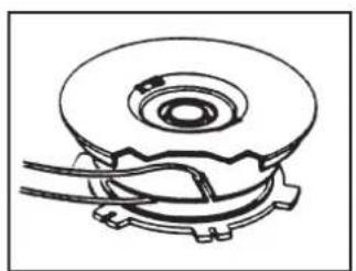
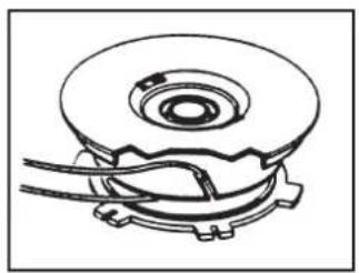
Cut an 8.6 metre length of trimmer line (∅ 2.4 mm). Fold it in the middle so you end up with two 4.3 metre lengths. Place the crease of the fold into one of the slots in the disc dividing the spool. See fig. A.
-
Wind both ends of the line around the spool clockwise. Hold the line with your fingers while winding to keep it taut. Stop when about 15 cm of line remains. See fig. B.
-
Press the ends of the line into the slots (F) on opposite sides of the spool. See fig. C.
-
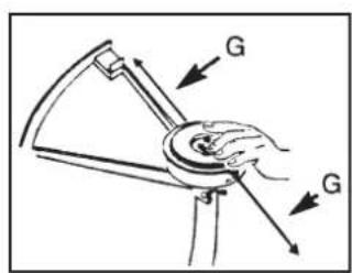
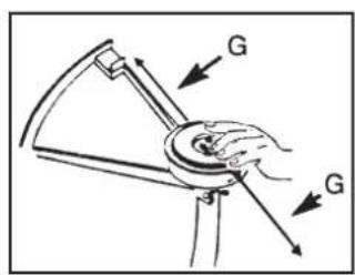
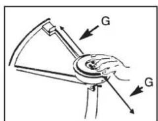
Push in the spring (C) on the bottom of the spool (if not already in). Pull the ends of the line through the holes (G) in the side of the housing (E). See fig. D.
-
Push the spool (B) into the housing whilst feeding the ends of the line through the holes (G). See fig. E.
-
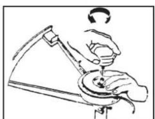
Press the spool (B) in so that the spring becomes compressed. Tug the ends of the line, freeing them from the line slots (F) in the spool.
-
Push the assembled trimmer head securely onto the spindle and hold it in position. Tighten the locking cap (A) anti-clockwise (only finger-tight). See fig. F.
-
Cut the ends of the line so they are no longer than 13 cm.

A. Locking cap
B. Spool
C. Spring
D. Spindle
E. Housing
F. Line slot
G. Line hole
H. Trimmer line
natural_image
Technical line drawing of a mechanical component with no visible text or symbols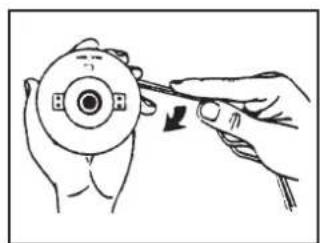
natural_image
Illustration of a hand using a tool to adjust a circular component with a knob (no text or symbols)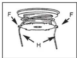
Fig. A Fig. B Fig. C
natural_image
Line drawing of a person using a tool to press or install a component, no text or symbols presentNever use the grass trimmer without an air filter. Clean or replace the filter if it is damaged or dirty. Clean the air filter like this:
- Undo the screw in the air filter cover that holds on the outer housing.
- Remove the outer housing and take out the filter from the inner cover.
- Wash the filter with soap and water. Do not use petrol!
- Squeeze the filter and let it dry naturally.
- Replace the filter and remount the housing with the opening facing downwards.
- Make sure that the housing is secure so that it won't shake loose.
9.3 Fuel cap/fuel filter
Remove any sources of ignition, sparks, open flames, lit cigarettes, etc. from the area where the fuel is mixed, used or stored. Do not smoke while refuelling or using the grass trimmer.
- Open the fuel tank carefully and release any pressure which might have built up in the tank. Wipe off any spillage and pour any remaining fuel into a petrol can.
- Pull out the fuel line/fuel filter using something like a bent wire.
- Pull out the fuel filter (twisting it a bit helps).
- Insert a new fuel filter. N.B. Never run the engine without a fuel filter.
9.4 Adjusting the carburettor
The carburettor has been factory adjusted for optimum power.
9.5 Spark plug
• Type of spark plug: NGK BM6A or Bosch WS8E
- Electrode gap: 0.65 mm
- Tightening torque: 12–15 Nm
9.6 Sharpening the line cutter knife (on the trimmer guard)
- Remove the cutter from the trimmer guard.
- Hold the cutter in a vice. Sharpen the blade using a flat file, sharpening in one direction only and making sure to maintain the original grinding angle.
10. Storage
- Clean the exterior of the grass trimmer, guard, trimmer head, spindle, the external parts of the engine, etc.
- Transfer any fuel remaining in the fuel tank to a petrol container.
- Start the engine when the fuel tank has been emptied.
- Allow the engine to idle until it cuts out to empty the carburettor of fuel.
- Allow the engine to cool for 5 minutes.
- Use a spark plug socket to remove the spark plug.
- Pour one teaspoon of pure 2-stroke oil into the cylinder via the spark plug hole, pull the starter handle slowly a few times to distribute the oil evenly over the inside of the engine, replace the spark plug.
- Store the grass trimmer in a dry and well ventilated place.
10.1 Using the trimmer after it has been stored
- Use a spark plug socket to remove the spark plug.
- Pull the starter handle quickly and smoothly a few times to remove the surplus oil from the cylinder.
- Clean the electrodes of the spark plug or replace it with a new one.
- Tighten the spark plug using a spark plug socket.
- Fill the fuel tank.
11. Troubleshooting
| Problem Possible cause Solution | ||
| The engine won’t start or only runs at low speed. | Incorrect starting procedure. | Read the instruction manual. |
| Dirt in the carburettor. Allow a qualified technician to clean the carburettor. | ||
| Faulty spark plug. Clean or change the spark plug. | ||
| Clogged fuel filter. Change the fuel filter (inside the fuel tank). | ||
| The engine starts but with loss of power. | Wrong choke setting. Open the choke. | |
| Dirty air filter. Clean or change the air filter. | ||
| Dirt in the carburettor. Allow a qualified technician to clean the carburettor. | ||
| The engine doesn’t respond to the throttle. | The engine is not warm enough. | Allow the engine to idle for a minute. |
| Loss of power under load. Faulty spark plug. Clean or change the spark plug. | ||
| The engine runs irregularly. Dirt in the carburettor. Allow a qualified technician to clean the carburettor. | ||
| The engine smokes a lot. Incorrect fuel mixture. Use petrol and 2-stroke oil with a 50:1 (2 %) ratio. | ||
N.B. The grass trimmer conforms to current safety requirements. Repairs to the grass trimmer should always be carried out using original spare parts and by a qualified technician. Failure to do so may result in injury.
12. Disposal
Follow local ordinances when disposing of this product. If you are unsure of how to dispose of this product, please contact your municipality.
13. Specifications
Model YT9071A
Dry weight 7.4 kg (without fuel and cutters)
Motor Air-cooled 2-stroke engine
| Cylinder volume | 35 cc |
| Fuel | Petrol/oil mixture 50:1 (2 %) |
| Max engine output | 1.6 hp (1.15 kW) at 7500 rpm (ISO 8893) |
| Max. spindle speed | 8500 rpm |
| Max engine speed | 10500 rpm |
| Idling speed | 2800 rpm |
| Direction of rotation | Anticlockwise (viewed from above) |
| Spark plug | NGK BM6A or Bosch WS8E |
| Tank capacity | 0.95 litres |
| Cutterhead | Nylon trimmer line: ∅ 2.4 mm,4-tooth brush cutter blade ∅ 230 mm, bore: 1" (25.4 mm) |
| Vibration level | 11.46 m/s ^2 (Full throttle) |
| Sound pressure level (EN 27917) LpA | 101.2 dB(A) K: 3 dB |
| Sound pressure level (EN 10884) LwA | 115 dB(A) K: 3 dB |
5. Montering
5.1 Montera handtaget
natural_image
Line drawing of a mechanical clamp or tool with a curved handle and cable, no text or symbols presentnatural_image
Close-up of a mechanical tool with a curved blade and metal rod, no visible text or symbols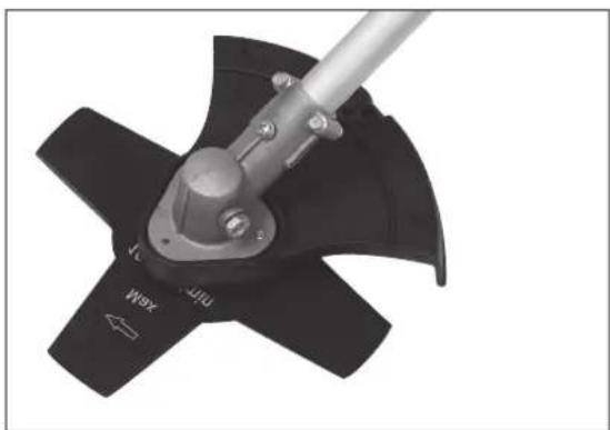
natural_image
Close-up of a mechanical power shaver with a metal lever and directional arrow (no text or symbols visible)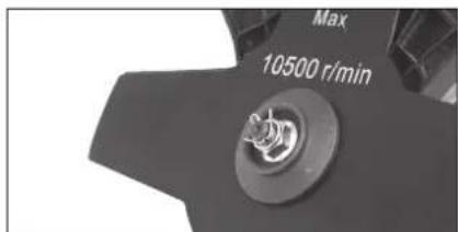
natural_image
Close-up of a mechanical component with a spherical object inserted, showing internal structure and no visible text or symbols.
natural_image
Technical line drawing of a mechanical component with no visible text or symbolsnatural_image
Illustration of a hand using a tool to adjust a circular component with a knob (no text or symbols)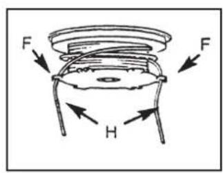
natural_image
Line drawing of a hand using a tool to press or install a component, no text or symbols present9.2 Luftfilter
3. Produktbeskrivelse
- Busk- og gresstrimmer med avtakbart skaft for enkel transport og oppbevaring.
• Motor 35 cm ^3 , effekt 1,15 kW (1,6 hk).
• Primerpumpe for enklere start - Reim
- Buskklinge 230 mm og trimmerhode med halvautomatisk trådmating.
• Vekt 7,4 kg
4. Benevninger
5. Montering
natural_image
Line drawing of a mechanical clamp or tool with a curved handle and cable, no text or symbols presentnatural_image
Close-up of a mechanical tool with a curved blade and metal rod, no visible text or symbols
natural_image
Close-up of a mechanical power shaver with a lever and mounting bracket (no visible text or symbols)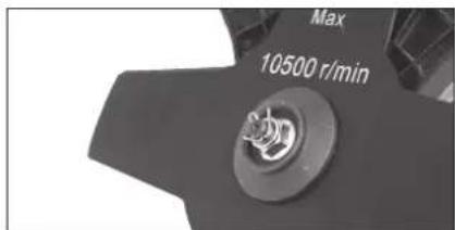
5.7 Sette sammen riggrøret
A. Mutteren/Låserattet
B. Spole
C. Fjær
D. Spindel
E. Deksel
F. Trådholder
G. Hull for tråd
H. Trimmerline
natural_image
Technical line drawing of a mechanical component with no visible text or symbols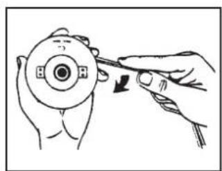
natural_image
Illustration of a hand using a tool to adjust a circular component (no text or symbols visible)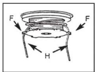
natural_image
Line drawing of a person using a tool to press or install a component, no text or symbols present3. Tuotekuvaus
5. ASENNUS
5.1 Kahvan asentaminen
natural_image
Line drawing of a mechanical clamp or tool with a cable and connector (no text or symbols)natural_image
Mechanical tool with a black wedge and metal rod, mounted on a circular base (no text or symbols visible)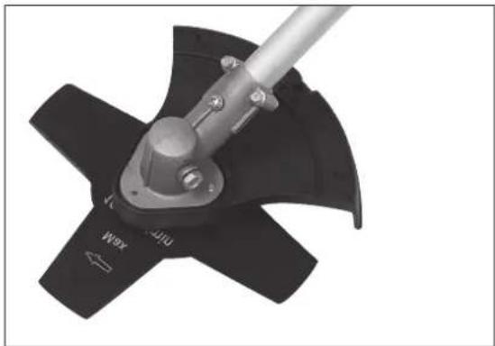
natural_image
Close-up of a mechanical power shaver with a metal lever and mounting bracket (no visible text or symbols)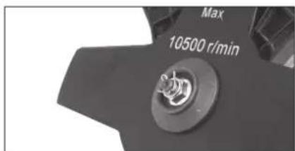
natural_image
Close-up of a mechanical component with a transparent spherical object inserted, showing internal structure and no visible text or symbols.
A. Nuppi
B. Kela
C. Jousi
D. Kara
E. Kupu
F. Siimanpidike
G. Siiman reikä
H. Trimmerin siima
natural_image
Technical line drawing of a mechanical component with no visible text or symbolsnatural_image
Illustration of a hand turning a circular device with a tool, no text or symbols present
natural_image
Line drawing of a person using a handheld device to press or install a small object (no text or symbols present)9.2 Ilmansuodatin
5. Montage
natural_image
Line drawing of a mechanical clamp or connector with a cable and two connectors (no text or symbols)natural_image
Mechanical tool with a black wedge and metal rod, mounted on a circular base with wires (no visible text or symbols)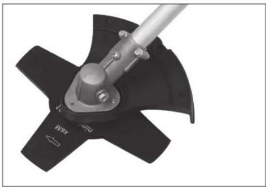
natural_image
Close-up of a mechanical power shaver with a metal lever and three blades (no visible text or symbols)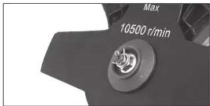
5.7 Rohr einbauen
natural_image
Close-up of a mechanical component with a spherical object inserted, showing internal structure and no visible text or symbols.
A. Rad
B. Spule
C. Feder
D. Spindel
E. Kappe
F. Fadenhalter
natural_image
Technical line drawing of a mechanical component with gears and a central hub (no text or symbols)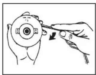
natural_image
Illustration of a hand using a tool to adjust a circular component (no text or symbols present)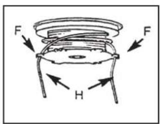
natural_image
Illustration of a person using a tool to press or install a component, no text or symbols presentDeclaration of Conformity
Machinery directive 2006/42/EC
EN ISO 11806-1:2011 E
EMC directive 2004/108/EC
N 55012:2002+A1 EN 61000-6-1:2001 EN 61000-6-3:2001+A11
VCA HEADQUARTERS, THE EASTGATE OFFICE CENTRE, EASTGATE ROAD, BRISTOL BS5 6XX, UNITED KINGDOM HAS CARRIED OUT THE TYPE APPROVAL. TYPE-APPROVAL NUMBER: e11*97/68SA*2004/26*0775*02
Klas Balkow President
Insjön, Sweden, 2013-11-04
SVERIGE
KUNDTJÄNST
Tel:
0247/445 00
Fax:
0247/445 09
E-post: kundservice@clasohlson.se
INTERNET
www.clasohlson.se
BREV Clas Ohlson AB, 793 85 INSJÖN
NORGE
KUNDESENTER
Tlf.:
23 21 40 00
Faks:
23 21 40 80
E-post: kundesenter@clasohlson.no
INTERNETT
www.clasohlson.no
POST
Clas Ohlson AS, Postboks 485 Sentrum, 0105 OSLO
SUOMI
ASIAKASPALVELU
Puh.: 020 111 2222
10 – 13 Market Place
Kingston Upon Thames
Surrey
KT1 1|Z
DEUTSCHLAND
KUNDENSERVICE
- Brush Cutter/Grass Trimmer
- Safety
- Product safety symbols and their meaning
- Guidelines for safe use
- Safety equipment
- Contents
- Product description
- Features
- Assembly
- Assembling the handle
- Attaching the blade guard/trimmer guard
- Double shoulder harness
- Accessories
- Attaching the blade/trimmer head
- Attaching the trimmer head
- Attaching the brush cutter blade
- Assembling the shaft
- Fuel and Lubrication
- Mixing the fuel
- Filling the fuel tank
- Caution!
- Starting the Engine
- Running in the engine
- Starting the engine from cold
- Starting a warm engine
- Switching the engine off
- Use
- Note!
- Trimming round trees and bushes
- Preparing the ground (removing all vegetation)
- Adjusting the trimmer line
- Using the 4-tooth brush cutter blade
- Maintenance
- Changing the trimmer line
- Fuel cap/fuel filter
- Adjusting the carburettor
- Spark plug
- Sharpening the line cutter knife (on the trimmer guard)
- Storage
- Using the trimmer after it has been stored
- Troubleshooting
- Disposal
- Specifications
- Montering
- Montera handtaget
- Luftfilter
- Produktbeskrivelse
- Benevninger
- Sette sammen riggrøret
- Tuotekuvaus
- ASENNUS
- Kahvan asentaminen
- Ilmansuodatin
- Montage
- Rohr einbauen
- Declaration of Conformity
- SVERIGE
- NORGE
- SUOMI
- DEUTSCHLAND
Brand : Cotech
Model : YT9071A
Category : Brush cutter