KG-1409B DYN - Cooker Mastercook - Free user manual and instructions
Find the device manual for free KG-1409B DYN Mastercook in PDF.


| Product Type | Freestanding Cooker |
| Brand | Mastercook |
| Model | KG-1409B DYN |
| Energy Type | Gas hob, Electric oven |
| Dimensions (H x W x D) | 850 x 500 x 600 mm |
| Weight | Approx. 40 kg |
| Power Supply (Oven/Ignition) | 220-240 V ~ 50/60 Hz |
| Number of Gas Burners | 4 |
| Oven Type | Electric fan-assisted |
| Oven Capacity | 60 liters |
| Oven Functions | Bake, Grill, Fan |
| Ignition System | Automatic electric ignition |
| Safety Features | Flame failure device on burners, heat-resistant oven door |
| Cleaning & Maintenance | Enamel interior, removable oven door |
| Spare Parts Availability | Contact Mastercook service center |
| Warranty | 2 years |
Frequently Asked Questions - KG-1409B DYN Mastercook
User questions about KG-1409B DYN Mastercook
0 question about this device. Answer the ones you know or ask your own.
Ask a new question about this device
Download the instructions for your Cooker in PDF format for free! Find your manual KG-1409B DYN - Mastercook and take your electronic device back in hand. On this page are published all the documents necessary for the use of your device. KG-1409B DYN by Mastercook.
USER MANUAL KG-1409B DYN Mastercook
natural_image
Modern kitchen interior with stainless steel appliances, a microwave oven, and a table with food (no visible text or symbols)Mastercook
1
6
text_image
3 7 8 10 8 9 1 4 2 11 12 5 6 1.1.1
text_image
min. 650mm max 850 mm min. 20mm 6.4.1
2
text_image
6.6.1 6.6.2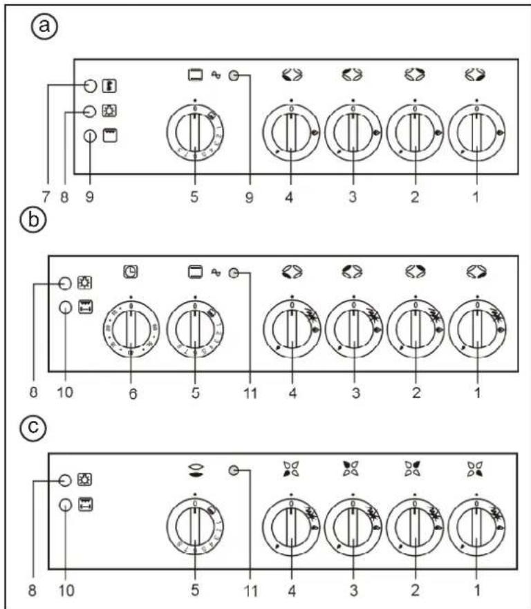
text_image
(a) 7 8 9 5 9 4 3 2 1 (b) 8 10 6 5 11 4 3 2 1 (c) 8 10 5 11 4 3 2 1KG 1319ZB Plus
KG 1319ZX Plus
KG 1320ZB Plus
KG 1320ZX Plus
KG 7520ZB Plus
KG 7520ZX Plus
KG 1409B DYN
7
8
text_image
7.4.1 A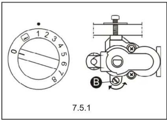
text_image
0 1 2 3 4 5 6 7 8 7.5.1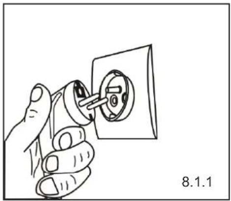
natural_image
Hand inserting a socket into an electrical outlet (no text or symbols visible)
text_image
9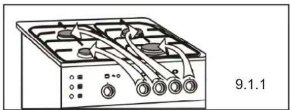
natural_image
Line drawing of a gas stove with cooling fans and control knobs (no text or symbols)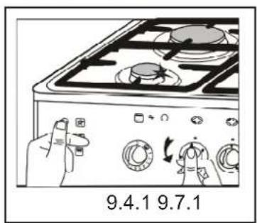
text_image
9.4.1 9.7.1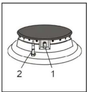
text_image
1 2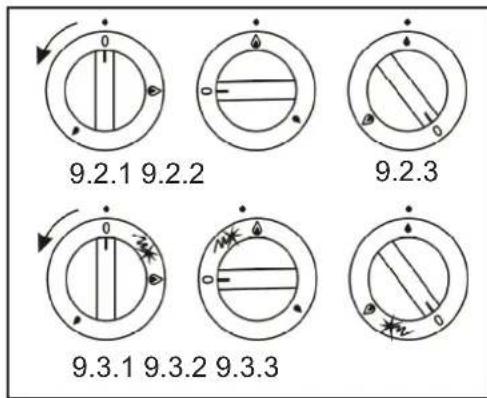
text_image
9.2.1 9.2.2 9.2.3 9.3.1 9.3.2 9.3.3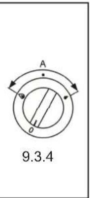
text_image
A 9.3.4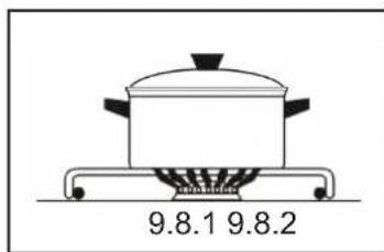
natural_image
Simple line drawing of a cooking pot on a gas stove (no text or symbols)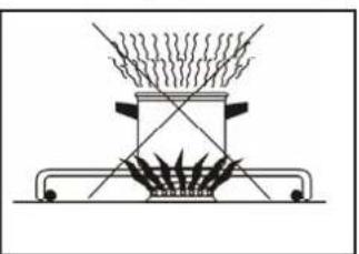
natural_image
Simple line drawing of a heating setup with a burner and steam rising from the top (no text or symbols)
10
text_image
4 2 3 1 10.2.1[5]
[4]
[3]
[2]
[1]
text_image
4 5 2 3 1 10.2.2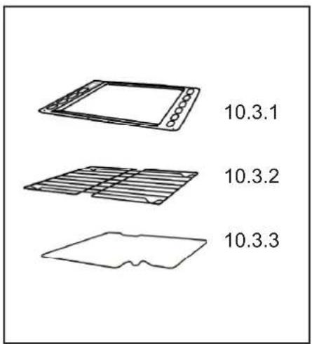
text_image
10.3.1 10.3.2 10.3.3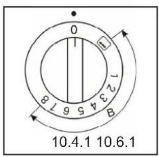
text_image
0 12345678 B 10.4.1 10.6.1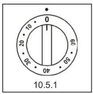
text_image
0 10 20 30 40 60 10.5.1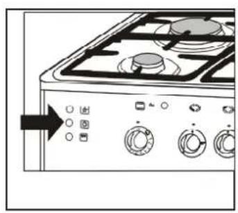
natural_image
Front view of a gas stove with control knobs and a rotary dial (no text or symbols visible)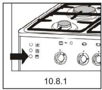
text_image
10.8.1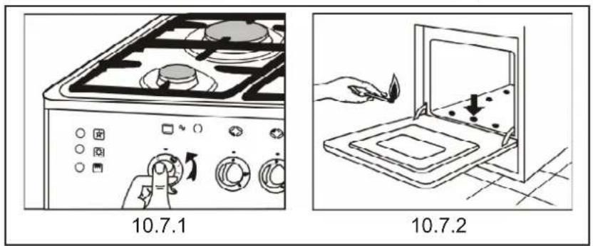
text_image
10.7.1 10.7.2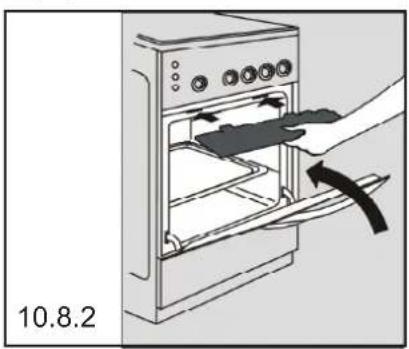
natural_image
Illustration of a kitchen appliance with an oven and a hand inserting a tray (no text or symbols)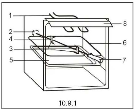
text_image
1 2 4 3 5 8 6 7 10.9.1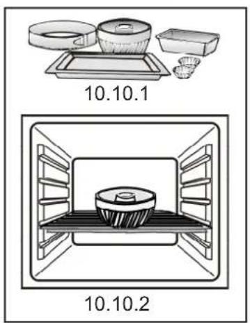
text_image
10.10.1 10.10.2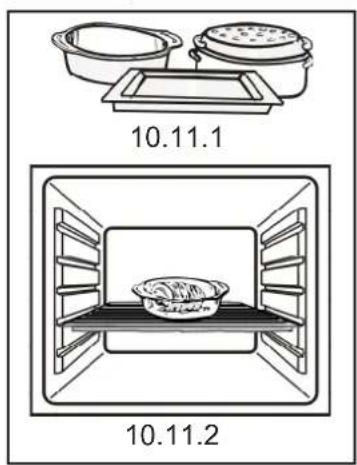
text_image
10.11.1 10.11.2
| 11 |
text_image
11.2.1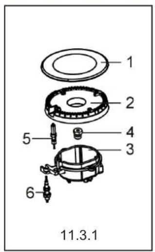
text_image
1 2 4 3 5 6 11.3.1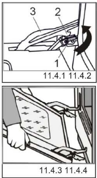
text_image
1 2 3 1 11.4.1 11.4.2 11.4.3 11.4.4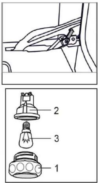
text_image
Technical diagram showing a mechanical component with three labeled parts: a bulb, a light bulb, and a flashlight.PL
natural_image
Simple line drawing of an open book with no text or symbols visible on pagesWAŻNE!
natural_image
Simple line drawing of an open book with no text or symbols visible on pagesВАЖНО!
The appliances comply with the following Directives:
2006/95/WE – The Low Voltage Directive
2004/108/WE - 2004/108/EC Electromagnetic Compatibility
90/396/EEC – The Gas Appliances Directive
natural_image
Simple line drawing of an open book with no text or symbols visible on pagesNOTE!
Before installing and operating the appliance, please read this instruction manual carefully. All graphic illustrations contained in this instruction manual are numbered. The numbers appearing on illustrations correspond to the numbers in the text.

1 Identification of the appliance
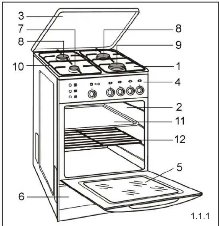
Your appliance is shown on Fig. 1.1.1.

2 Product specifications
2.1 This gas cooker is intended for preparing meals at household only. This appliance must not be used for other purposes.
2.2 Class of appliance: 1 (stand-alone)
2.3 Gas type: II 2H3B/P
2.4 Burner nominal output:
Small burner: 1.0 kW
Medium burner: 1.75 kW
Large burner: 3.0 kW
Oven burner: 3.2 kW
2.5 Construction and accessories (fig. 1.1.1):
1 – gas hob
2 - gas oven
3 – lid
4 - control panel
5 - oven door
6 - drawer
7 – small burner
8 - medium burner
9 – large burner
10 - grid
11 – baking tray
12 - baking grid
2.6 Control panel (a, b, c):
1, 2, 3, 4 – burner knobs
5 - oven control knob
6 - timer knob
7 – sparker button
8 - oven light button
9 – grill button
10 – roasting spit and grill button
11- indicator light

3 Important information!
-
This appliance is not intended for use by individuals (including children) with impaired physical, mental or sensory functions or individuals with insufficient experience or knowledge of the appliance, unless the use of the appliance by such persons takes place under proper supervision or in accordance with the instructions supplied to them by persons responsible for their safety. Never let children play with the appliance.
-
The appliance must be installed in accordance with the regulations in force and should be used only in well ventilated rooms.
-
Packaging materials should be kept away from children as they might be very dangerous for them.
-
The product should be installed 8 hours after it has been placed in the kitchen.
-
Prior to installation, ensure that the local supply conditions (type of gas and gas pressure) and the adjustment conditions are compatible with the specifications indicated in the nameplate.
-
The appliance should be connected to the gas supply system or LPG cylinder and adjusted only by a certified fitter of gas appliances or a technician of an authorised service centre, which should be indicated on the product's warranty card. The lack of such confirmation will render the warranty null and void.
-
In the event of failure, particularly gas leaks or short-circuits, turn the appliance off and contact your authorized service centre immediately. A faulty appliance must not be used until repaired.
-
The manufacturer declines any responsibility for injury or damage due to the improper installation or use of the appliance.
-
No unauthorized repairs are allowed, except for replacing the oven lamp bulb, on pain of voiding the warranty rights.
EN
- Never lift the cooker by taking hold of the handle

on the door of the oven
- In order to upgrade the appliance and to continually improve its quality, the manufacturer reserves the right to introduce changes in the appliance, without prior notification to the users. However, such modifications will not cause any difficulties in using the appliance.

4 Safety recommendations
When in use, the cooker becomes very hot. Care should be taken to avoid touching hot elements inside the oven. Special attention should be paid to children.
Connection leads of other household electrical equipment used while the cooker is being operated should be kept away from its hot elements. Care should be taken not to press connection leads with the hot oven door.
Use dry protective gloves when moving the dishes • off the gas hob or the baking tins out of the oven. Overheated fats and oils may easily catch fire, therefore the dishes prepared with fat or oil should only be cooked under supervision. Never leave the appliance unattended with gas burners turned on. Inflammable items should be kept well away from • the burners.
Never place inflammable or heat-sensitive items in the drawer or inside the oven.
Never overload the oven door when open. Do not sit or stand on it.
Never place deformed or unstable cookware on • pan supports as they may turn over and spill the burners.
Never put empty cookware on a lit burner.
Never place pots on gas burners if they protrude • outside the gas hob.
Before taking a dish off the burner, reduce the flame or put it out completely.
Heat and humidity are generated in rooms where cooking or baking appliances are installed and used. Ensure good ventilation in the kitchen – make sure that ventilation grates are open or install mechanical ventilation devices (a hood with mechanical absorption of odours).
Intensive and long-term use of the appliance may require additional ventilation, e.g. opening the windows or increasing the effectiveness of ventilation system by setting the hood control to a higher level, if available.
It is recommended to clean the lid before lifting it • off the hob.
When the oven is in use the lid should always be open.
Allow the gas hob to cool down before covering it • with a lid.
Turn all burners off before closing the lid. Glass lid •
may break when heated

Never make any unauthorized adjustments to the appliance, e.g. converting it to a different type of gas or modifying the gas or power supply system.
- Do not use the appliance for heating rooms.
In the event of an escape of gas, immediately close the valve on the gas supply line or a gas cylinder, ventilate the room thoroughly and call gas emergency service. During that time you must not light matches, smoke cigarettes, turn on or off any electrical appliances (radio, electric bell, light switch, etc) or mechanical appliances which produce sparks.
Should there be a leak on the gas cylinder valve and flames appear, throw a wet blanket over the cylinder so that it cools down, and shut off the cylinder valve. Never use damaged gas cylinders!
5 Preparing the appliance for use
- After removing the packaging, check the appliance for any visible damage. Do not install the cooker if the appliance has been damaged during transport.
- Remove all stickers from the appliance. Clean all parts of the cooker thoroughly to remove the remaining glue.
- Wipe the enamelled and glass surfaces with a soft damp cloth.
- Make sure that all parts of the burners are positioned correctly.
•5. Take the accessories out of the oven, remove the protective foil and wash them with warm water with the addition of a detergent. - Close the oven door and light the oven by setting the oven burner knob to "8". The oven should operate for about 30 minutes. The smell produced during this procedure is only slight, provided that the room is well ventilated, e.g. by opening the windows. After the oven cools down, wash and dry it.
6 Positioning the cooker
The room where the cooker is to be installed should be dry and well ventilated.
The position of the cooker should ensure free access to all controls. It is not recommended to place the appliance on the base.
The appliance should be installed away from flammable materials. The kitchen wall adjacent to the cooker should be made of non-flammable materials.
Provide sufficient open space above the cooker to allow cooking vapours to dissipate. A ventilating hood can be installed in order to absorb or discharge the vapours. The distance between the gas hob and the hood should be at least 650mm (fig. 6.4.1).
The cooker should be installed in a set of cabinets • not higher than 850mm. Do not fit kitchen cabinets over the cooker.
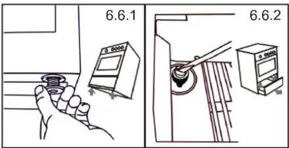
The cooker is fitted with levelling feet which allow - adjusting the level of the appliance. The feet are accessible after removing the drawer (fig. 6.6.1) or tilting the cooker (fig. 6.6.2). Rotate the feet one way or other, as required.
7 Installation
This appliance should not be connected to fume exhaust pipes. It should be installed and connected in observance of valid regulations – in particular concerning ventilation.
- The cooker is equipped with a G ^1/2 " stub pipe. Using proper fittings connect the stub pipe to the gas supply system.
The cooker may be connected to the natural gas • supply system or LPG cylinder.
Before proceeding with the connecting activities, make sure that the gas tap is closed.
It is recommended to seal the connections with a • Teflon tape.
7.1 Connecting to the natural gas supply system
The cooker may be connected to the gas supply • system using a rigid pipe or a flexible metal hose conforming to the requirements of national standards.
The maximum length of the flexible hose must not exceed 2.0 m. The hose must not come into contact with any moving parts. Sufficient space must be provided for the hose.
When connecting to a rigid pipe, care must be taken to avoid exposing any part of the device or point of gas installation to excessive mechanical stress.
7.2 Connecting to an LPG cylinder
If you wish to use an LPG cylinder, do not install the cooker in the basement or in any other room where the floor is below the ground level, as LPG is heavier than air and accumulates at the floor level.
When connecting the appliance to an LPG cylinder, use a rubber hose conforming to the requirements of national standards.
To connect the cooker with a rubber hose, use a steel pipe with the length not less than 0.5 m.
The length of the rubber hose should not exceed 1.5 m. The hose must not be choked, twisted or bent sharply and must be accessible along its entire length.
The hose must not be laid near any sources of • excessive heat (max. 50°C).
Broken hose must be immediately replaced. Any repairs to a leaky hose are strictly forbidden.
Every time you connect the cooker to the LPG cylinder, check the air tightness at the cylinder valve and at the connection of the regulator to the cylinder, and its operation.
WARNING!
- Under no circumstances can the air tightness be checked by means of a naked flame (e.g. with a match or candle). Danger of explosion! Use soapy water to check the air tightness.
- The condition of the hose and the tightness of the connection should be checked periodically in accordance with the applicable regulations.
- Rubbed hose must not come into contact with any hot elements of the cooker.
7.3 Replacing the nozzles
If it is required to change the type of gas supplied to the cooker, it is necessary to replace the nozzles and fill in the "Gas Conversion" sticker supplied with the appliance in a plastic seal containing the warranty card and the instruction manual. Upon specifying what type of gas the appliance was converted to, put the sticker on the appliance.
Replacing the nozzles:
shut off the valve cutting off the cooker from the – gas supply system or from the cylinder, –turn off all gas taps in the cooker, remove pan supports, lids and rings from burners – on the gas hob,
EN
remove the nozzles and replace then according – to Table 1,
put hob burners' lids and rings back into place, – adjust the hop burner taps and the oven burner – taps,
check the connections for soundness. —
7.4 Adjusting the hob burner taps
The adjustment of hob burner taps is accomplished by setting the flame on the burner in the simmering position.
Adjusting the taps:
open the gas flow with the knob and light the bur- ner to be adjusted,
set the knob in simmering flame position, and – then, maintaining that position, remove the knob from the tap pin and watch the burner's flame,
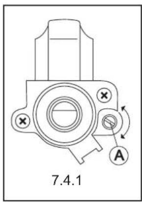
- turn the adjustment screw “A” (fig. 7.4.1) and watch the flame; set the flame to such a size that will prevent it from being extinguished by a slight draught or during the operation of quickly turning the knob from the full to the simmering position of the flame and back,
the adjustment is correct when the core of the flame is cone-shaped in green and blue colour and is ca. 2 – 4 mm tall,
if there are perceptible changes of gas pressure – in the gas supply system (change in the size of flame at full flow), the simmering flame should be set when pressure in the system is low to prevent the burner from extinguishing during normal use, upon adjusting the taps, put the knob back in its position and turn off the flame.
The amount of gas used with taps set to minimal gas flow corresponds to ca. 25 % of use when the taps are set to full flame.
Table 1 Burner nozzle specification
| 2E-G20 20mbar 2E-G | 20 13mbar 3B/P-G30 30mbar | |||||
| Small burner X072 084 | 050 | |||||
| Medium burner | Z097 | 110 | 065 | |||
| Large burner Y118 145 | 085 | |||||
| Oven burner | P1 | P9 | P2 | |||
| Arrangement of burner nozzles | BackFront | Z097HOBX072Y118 | BackFront | 110HOB084145 | BackFront065HOB050085 | |
| Oven | Lowerburner | OVENP1 | Lowerburner | OVENP9 | LowerburnerOVENP2 | |
7.5 Adjusting the oven burner taps
The adjustment of oven burner taps is accomplished by setting the flame on the oven in accordance with Table 2.
Adjusting the taps:
–take out the accessories from the oven,
—place the thermocouple in the oven,
– light the oven burner,
- set the oven control knob in position „1” (fig. 7.5.1) and remove the knob from the tap pin,
– close the oven door and heat the oven, after heating the oven check the temperature re- – ading on the sensor,
- if the temperature in the oven for position „1“ does not correspond to Table 2, then using a long flat screwdriver turn the adjustment screw „B“ in the right direction to increase or decrease gas flow,
- wait a few moments for the temperature in the oven to stabilize; watch the temperature sensor,
- if necessary, repeat the adjustment procedure, upon adjusting the taps, put the knob back in its - position and turn off the flame.
8 Connecting the cooker to power supply
8.1 The cooker is equipped with the power cord with a plug and must be connected to a mains socket properly fitted with earth contact (fig. 8.1.1).
8.2 Connecting the cooker to a socket not equipped with a grounding prong can result in electric shock should the cooker electrical installation be damaged.
WARNING!
- The mains socket should be easily accessible to the user.
2. Make sure that the power cord does not come into contact with hot parts of the cooker.
9 Using the gas hob
9.1 Knobs
The gas flow in particular burners is opened and closed with the use of knobs fitted on the gas taps. Before turning the burner on, make sure that the knob you are about to turn corresponds to the burner which is to be used. The burners and their corresponding knobs are shown in fig. 9.1.1.
9.2 Setting the flame
The flame should not lick around from the bottom of a pan. The size of flame depends on the position of the knob (fig. 9.2.1, 9.2.2, 9.2.3, 9.3.1, 9.3.2, 9.3.3).
0 – burner switched off (flow of gas shut off)
- large flame
- small flame (simmering)
9.3 Using the flame
Large flame (fig. 9.2.2 and 9.3.2) should be used until the liquid is brought to boiling after which the flame should be turned down and further cooking continued over a small flame (fig. 9.2.3 and 9.3.3). The size of the flame should be adjusted only within the range of small and large flame: ⚠️ (fig. 9.3.4).
9.4 Lighting the burners
Cookers are equipped with a flame failure safety device which cuts off the gas flow to the burners when the flame is extinguished, e.g. by overflowing food.
press the knob of the selected burner all the way in, turn it in the counter-clockwise direction and hold until the burner has ignited,
in cooker 1319ZB/X Plus - press the knob of the - selected burner all the way in, turn it in the counter-clockwise direction and simultaneously, push the sparker button and hold it until the burner has ignited,
when the burner has ignited, keep the knob pu- shed in for ca. 5 seconds to allow the flame failu- re device to energise,
release the knob and set the size of the flame. –
If the flame has accidentally extinguished, close the gas flow and wait for at least 1 minute before retrying to reignite the burner.
9.5 Extinguishing the burners.
Turn the burner knob in the clockwise direction to its "0" position.
9.6 Lighting the burners (cookers supplied from an LPG cylinder)
Before lighting the first burner, open the valve on the LPG cylinder, and then light the burner in accordance with the above described.
When cutting off the gas flow, prior to extinguishing the last burner:
close the valve on the LPG cylinder, – when the flame has gone out, close the tap of that – burner.
When the cooker is not in use, the valve of the LPG cylinder should be closed.
9.7 Burners
1 - sparker
2 - end of thermocouple (flame safety device)
9.8 Cookware selection
Cookware base diameter should be 2.5 - 3 times • greater than the diameter of the burner ring (fig. 9.8.1). Cookware should not protrude outside the gas hob grid and the flame should not lick around from the bottom of a pan (fig. 9.8.2),
Cookware should always be clean and dry as it will • then conduct and retain heat well,
During cooking, the cookware should be covered • with lids to prevent excess amounts of vapour from accumulating in the kitchen.
- Minimal cookware dimension:
- for small burner - ∅ 90 mm
- for medium burner - ∅ 160 mm
– for large burner – ∅ 200 mm
10 Using the oven
- The oven burner is located beneath the floor of the oven. It is equipped with a flame failure safety device which cuts off the gas flow to the burners when the flame is extinguished, e.g. by draught or overflowing food.
Before lighting a burner, the oven door should be opened for 3 - 4 minutes to vent the oven.
After lighting the gas, the temperature in the oven • settles after about 10 minutes and is fixed for the set position of the knob.
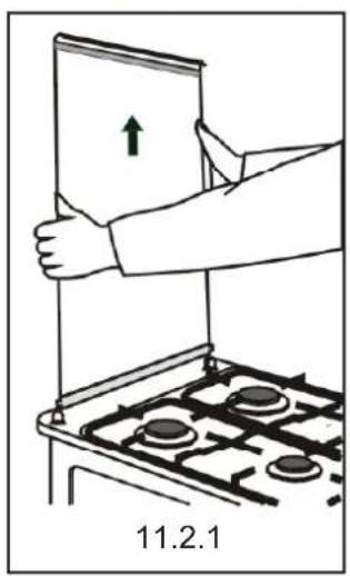
When operating the appliance, it is recommended to remove the lid (in accordance with fig. 11.2.1) to prevent it from becoming soiled.
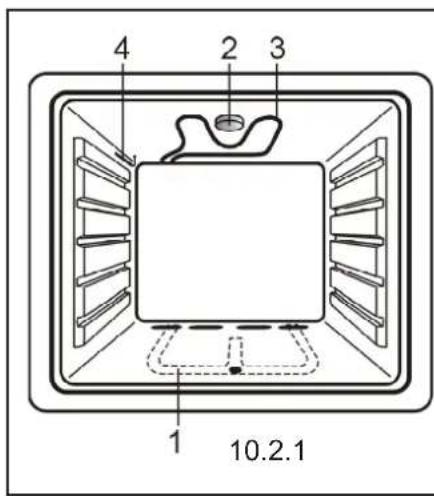
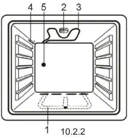
10.2 Elements of the oven (fig. 10.2.1, 10.2.2)
[1], [2], [3], [4] – guide levels
1 – oven burner
2 - oven lamp
EN
3 – grill heater
4 - temperature sensor
10.3 Accessories
Depending on the model, various cookers may be equipped with the following accessories:
baking tray (10.3.1)•
roasting grill (10.3.2)•
roasting-spit frame (10.3.3)•
10.4 Oven control knob
The oven control knob (fig. 10.4.1) enables to open and close the gas supply and to set the requested temperature in the oven. The requested temperature can only be achieved when the oven door is closed.
Settings from 1 to 8 are indicated on the knob. They correspond, more or less, to the temperatures given in Table 2. The knob can be rotated only in one direction, i.e. from position 1 to 8.
10.5 Timer
The electronic timer serves as a sound alarm which can be used for short cooking operations (10.5.1). It is not used for controlling the cooker's functions. It can be set within the range between 0 – 60 min.
Setting the alarm
First, turn the timer knob all the way right, than – set the desired time, e.g. 20 min.
10.6 Oven light
The oven has been fitted with a light bulb which lights up the inside of the oven during its operation.
You can turn the light on/off using the switch (10.6.1).

10.7 Turning the oven
10.7.1 Lighting the oven burner:
– open the oven door completely
-light a match
- press the knob of the selected burner all the way in, turn it in the counter-clockwise direction (10.7.1) and put a lit match to the burner (10.7.2); keep the knob pushed in for ca. 5 seconds to allow the flame failure device to energise
– release the knob
- if the flame goes out, repeat all the steps, this time pushing the knob in for an additional 5 seconds.
If the flame has accidentally extinguished, close the gas flow and wait for at least 1 minute before retrying to reignite the burner.
10.7.2 Extinguishing the oven burner
Turn the burner knob in the clockwise direction to its "0" position.
10.8 Using the electric grill
NOTE!
- When in operation, the appliance must not be left unattended, as certain parts of the cooker may become very hot. Keep children well away!
- Dishes must not be placed on the highest level [5], directly below the grill heater.
This function is intended for grilling small size dishes (steaks, frankfurters, sausages, kebabs, fish, toasts, krouts, etc.)
The dish should not be thicker than 2 - 3 cm. It should be placed on a baking tray or a roasting spit on the middle level of the oven. When grilling meat on a roasting-spit, place a drip tray under the grilled dish.
Before grilling meat and fish, smear them with a small amount of fat.
The grilling time is assumed approximately 8 - 10 · minutes per each centimetre of thickness.
Operating the oven:
- remove all unnecessary accessories from the oven and close the oven door,
- using the button turn on the oven heater, - preheat the oven for a few minutes,
- put the dish inside the pre-heated oven, place it on the griddle or in a pot centrally below the grill.
- mount the knob protection screen (10.8.2)
– after half of the grilling time turn the grilled portions over.
Turning off the oven.
After grilling, turn off the oven using the button

10.9 Grilling with the roasting-spit
Roasting-spit is used for rotary grilling of poultry, sausages, kebabs, etc.
Description to fig. 10.9.1:
1 – grill heater
2 - roasting-spit drive
3 – forks
4 - spit
5 - baking tray (drip tray)
6 - roasting-spit frame
7 - handle
8 - knob protection screen
When using the oven, follow these instructions:
– remove all unnecessary accessories from the oven and mount the roasting-spit frame (6) (10.9.1)
– slide one fork (3) onto the spit (4) and thread the meat on it; make sure the meat is placed symmetrically along the spit (4)
– slide the second fork in (3) and secure it in its position by tightening the screw
insert the pointed end of spit into the roasting-spit drive (2), push it all the way in and rest the other end of the spit on the frame (6)
- remove the handle (7), mount the knob protection screen and using the button turn on the oven heater (1) and the spit drive.
To turn the grill and roasting-spit off press the button.

NOTE!
After pressing the button ☐ or ☐ the oven control knob should be set to the position "0" or otherwise the oven heater will turn off automatically.
10.10 Baking cakes
- Before putting a cake into the oven, the oven must be pre-heated, with the oven door closed, so that the temperature in the oven is even.
- Preheat temperature, baking temperature and baking time should be selected taking into consideration the type of cake or dish to be cooked, according to the recipe.
- The oven should be preheated very carefully. It should be used especially for baking thick and heavy cakes. If you place dough in the overheated oven, the cake may be doughy or fail to rise.
- In the initial phase of baking, the dough rises. Fast rising dough should be put into an oven preheated less, so that the outer layer does not become burnt too fast. Towards the end of baking the temperature should be decreased so that the outer layer of the cake does not become too dry and too thick.
- For baking cakes, traditional metal cake tins may be used as well as Teflon, ceramic or glass cake trays (fig. 10.10.1). Before first use, all metal cake tins must be baked in a well-heated oven.
- Fill the tins 2/3 full of dough, leaving enough place for it to rise.
- When selecting the baking time and temperature take into account the weight and consistency of the pastry.
- Place utensils with food centrally on the grid (10.10.2) at any level of the oven. Observation and experience help in choosing the best level, temperature and oven function for a particular dish.
- In order to check whether the cake is baked, it should be pierced with a thin wooden rod a few minutes before switching off the oven. The cake is ready if it does not stick to the rod. After baking the cake should be kept in the oven for about 5 minutes.
- Remove all unnecessary accessories from the oven before baking.
10.11 Roasting meat
- Ceramic, glass, enamelled steel and cast-iron cookware with heat-resistant handles may be used (fig. 10.11.1) for roasting meat. For better heating the cookware should be relatively low. Meat can also be roasted directly on the grid. In such case always put a drip tray under the grid.
- Roasting temperature should be adjusted to the type and size of meat. The bigger the piece of meat, the lower the temperature and the longer the roasting time should be. Smaller pieces of meat, on the other hand, require higher temperature and shorter roasting time.
- Place the dish on the grid centrally in the oven (10.11.2).
Important!
Below in tables the approximate cooking times for various foods have been summarized. These are only suggestions and in practice these values may vary depending on oven temperature, amount and type of food, etc. We recommend making several tries for a particular dish and noting down the optimum time and temperature.
Table 3 Cake
| Kind of cake | Temperature [ ^0 C] | Timing [min] |
| Raised cake (depending on size) | 180 | 15 - 50 |
| Yeast cake | 150 – 160 | 20 - 40 |
| Sponge | 160 | 20 - 30 |
| Short crust | 200 | 25 – 40 |
| Puff pastries | 200 – 250 | 15 - 20 |
| Cookies | 170 | 30 - 50 |
Table 4 Roasting of meat
| Kind of dish | Timing [min] | |
| One side | Second side | |
| Thin portions of meat | 6 | 4 |
| Thick portions of meat | 8 | 6 |
| Fish | 10 | 8 |
| Sausages | 12 | 10 |
| Toast | 5 | 2 |
| Small poultry | 20 | 15 |
EN

11 Cleaning and maintenance
NOTE!
Before proceeding with cleaning, disconnect the cooker from the power supply.
11.1 General Tips
The cooker should be kept clean. The following may not be used for cleaning: abrasive powder cleaners, metal scouring pads, aggressive chemical agents or sharp objects.
Stainless steel elements, knobs, dials and the control panel should be cleaned with mild liquid detergents containing no abrasive agents.
For enamelled parts use a soft brush or sponge moistened with warm water containing mild detergents, avoiding excessive water. For heavily soiled surfaces use kitchen-cleaning agents.
When cleaning the hob do not allow water to get • beneath the hob. The hob surface around burners should always be clean as dirt deteriorates the combustion of gas. Burners and igniters must be kept clean and dry to ensure their trouble-free operation. Clean the burners and igniters each time they become spilled and also periodically remove blooms or dirt.
Take the dirty grids off the gas hob, soak them in warm water with detergent and then wash and dry them.
Immediately after use, trays and tins for baking and roasting should be soaked in warm water with detergent and then washed and wiped dry.
Oven door gasket should be kept clean.
11.2 Cleaning the lid
The lid can be removed before cleaning the cooker.
Removing the lid:
– open the lid completely (11.2.1),
- using both hands grasp the lid on the sides, lift it up and remove it.
Clean the lid with a soft cloth using a mild detergent, rinse, wipe dry and put away.
11.3 Cleaning the burners
Elements of the burners (fig. 11.3.1)
1 – lid
2-ring
3 - body
4 - nozzle
5 – sparker
6 – thermocouple
To clean the burners remove the lid and the ring •
of the burners, put them in warm soapy water for some time and then wash each part of the burner separately.
Clean the burner elements using a sponge or a soft brush and remove dirt from burner ports with a steel wire. After cleaning check if the burner ports are clear.
To avoid permanent stains, rings should be washed • each time after they become soiled.
The hob surface around the burner should be kept • clean at all times. Dirt may clog the nozzle, which results in reduced gas flow or stoppage.
The nozzle should be cleaned with a small paint-• brush dipped in a solvent.
Dry all the elements of the burners carefully as wet elements may not light or cause the gas to combust improperly. Assemble clean and dry burners
carrying out the disassembling steps in the reverse order, taking care not to damage the sparkers.
11.4 Cleaning the oven
NOTE!
It is forbidden to clean the oven with the use of • steam pressure cleaners.
- As the hinge's bow is very tight, remove the doors carefully to avoid hurting your fingers.
To facilitate cleaning of the oven you can remove the oven door.
Removing the oven door:
– open the door completely,
- lock the hinges (fig. 11.4.1) at each side by fitting clip 1 onto catch 2 of hinge bow 3 (fig. 11.4.2),
- grasp the door with both hands, turn it by about 45^ (in the closing direction) and pull the hinges out of their seats (fig. 11.4.3).
The oven chamber is coated with ceramic ena-1. mel.
- For enamel surfaces use kitchen-cleaning agents.
For removing difficult baking stains, special oven 3. cleaning agents are recommended. However, these agents are caustic and therefore should be used in small quantities and with utmost care.
Please follow the manufacturer's instructions carefully.
If the light bowl is dirty, unscrew the bowl, and 4. wash and dry it thoroughly (fig. 11.4.4).
During cleaning the upper wall of the oven pay 5. attention to electric heaters, temperature sensor and the oven lamp; do not change position of sensor setting.
Refit the door carrying out the removal steps in 6. the reverse order.
12 Troubleshooting
NOTE!
Before proceeding with the troubleshooting, disconnect the cooker from the power supply to avoid being electrocuted.
In the warranty period all repairs except for the • ones specified below should be carried out by the authorised Servicing Point.
If there are some disturbances during the use of the appliance, follow the guidelines below to check if you can repair the defect yourself.
| Problem Solution | |
Igniters fail to ignite or not always ignithe gas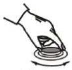 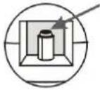 12.1.1 12.1.2 12.1.1 12.1.2 | Check to make sure the cooker is connected to the electrical mains. - Clean and dry the igniters and burner components. - Check to make sure the burner caps and heads are placed correctly. - Press on the burner cap and rub it against the head by turning right and left (fig. 12.1.1).Rub the igniter electrode with the use of hard brush or smooth file (fig. 12.1.2). |
Gas burners fail to ignite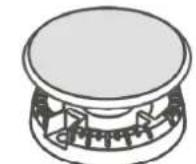 Do not floodwith water Do not floodwith water | - Check to make sure the rubber hose supplying gas from the gas cylinder is not squeezed.- Check to make sure the gas main valve is open.- Check to make sure the gas cylinder is not empty.- In case a new cooker has been installed or the gas cylinder has been replaced with a new one, then it is necessary to repeat the ignition procedure until the gas reaches the burner.Check to make sure the nozzle or burner flame holes are not clogged or flooded. If so, un-clog the nozzle hole using a pin or needle. Clean the burner flame holes with the use of brush, and then dry all components. |
Flame dies after releasing the knob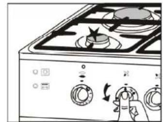 | Your cooker is equipped with a flame failure safety device- Where the ignition device is built in the knob set the knob to large flame , press the knob and when the gas has ignited keep it pressed all the way in for another few seconds. . |
While igniting one of the burners all the hob burner igniters spark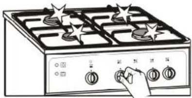 | It is normalWhen pressing the selected knob (with a built-in ignition device) or the ignition button sparks are re-leased at all the burners . |
| After setting the knob to simmering flame position - the flame dies or is too high | -Avoid draughts in the kitchen,- Call the fitter to adjust simmering flame position . |
| Flame is unstable | Check to make sure that the burner components are clean, dry and - placed correctly. |
EN
Parts made of stainless steel (inox) develop stains that cannot be removed with the use of standard cleaners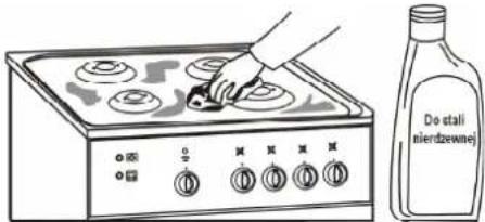 | - Stainless steel surfaces should be cleaned each time they get soiled and only with the use of special stainless steel cleaner. |
Smoke coming out of the oven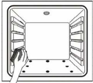 | Open the windows to air the kitchen, - - When the oven cools down, clean its interior and especially the spit. Use the drip tray when grilling foods. - |
Oven light does not function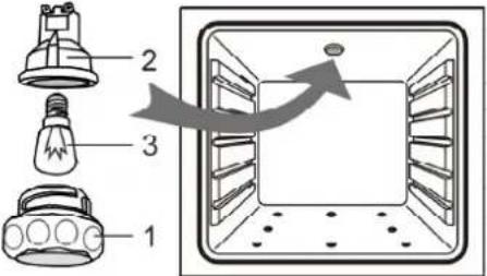 | 1. Check to make sure the cooker is connected to the electrical mains. 2. The bulb is burnt or not screwed all the way in.Disconnect the cooker from the electrical mains before fixing the fault.- Unscrew glass bowl 1 from light socket 2 and screw bulb 3 all the way in or replace the bulb with a new one (bulb type: E14 230V 25W, resistant to temperature of 300^ ). |
| Damaged power lead In order to avoid hazards, damaged power lead should be exchanged at the manufacturer's or by a specialist servicing point, or by a qualified person. | |
| Cooking results are not what you expected | The cooking parameters given in the instruction manual should be treated as guidance only. In practice, these parameters are dependable on the weight and consistency of food, cooking tray level, etc. Therefore, we recommend making a few trials for your favourite foods and then writing down the optimal time and temperature. |
| NOTE !If after completing the above steps the appliance is still inoperative contact your local service centre. | |
13 Environment
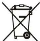
This device is labelled, in accordance with Council Directive 2002/96/EC, with a symbol of a crossed garbage container.
This labelling means that the device, upon end of its life cycle, should not be disposed of together with other household waste.
The user is responsible for having the device collected by appropriate entities responsible for disposal of used electrical and electronic devices.
Appropriate disposal of used electrical and electronic devices allows to avoid hazards to the humans and the environment connected with inappropriate storage and processing of such devices.