
RBS-5518 - Band saw RYOBI - Free user manual and instructions
Find the device manual for free RBS-5518 RYOBI in PDF.

| Product type | Band saw |
| Brand | RYOBI |
| Model | RBS-5518 |
| Supply voltage | 230 V (1~50 Hz) |
| Power | 780 W |
| Rated current | 3,5 A |
| Protection | IP 54 |
| No-load speed | 1400 ± 10% min⁻¹ |
| Cutting speed (fast) | 800 ± 10% m/min |
| Cutting speed (slow) | 370 ± 10% m/min |
| Band dimensions | 2240 mm long, max. 15 mm wide, 0.5 mm thick |
| Maximum cutting height | 180 mm |
| Dimensions (L × W × H) | 590 × 505 × 1265 mm |
| Weight | 67 kg (excluding accessories) |
| Sound level (no-load) | LPA 67 dB(A) / LWA 78 dB(A) |
| Sound level (machining) | LPA 85 dB(A) / LWA 91 dB(A) |
| Tiltable table | Up to 45° |
| Safety devices | Switch with emergency stop, upper and lower slides, chip guard |
| Routine maintenance | Band change, cleaning, guide adjustment |
| Available spare parts | Bands, rubber linings, chip guard, drive belt |
Frequently Asked Questions - RBS-5518 RYOBI
User questions about RBS-5518 RYOBI
0 question about this device. Answer the ones you know or ask your own.
Ask a new question about this device
Download the instructions for your Band saw in PDF format for free! Find your manual RBS-5518 - RYOBI and take your electronic device back in hand. On this page are published all the documents necessary for the use of your device. RBS-5518 by RYOBI.
USER MANUAL RBS-5518 RYOBI
natural_image
Technical line drawing of a mechanical device with mounting base and clamping mechanism (no text or symbols)Important! It is essential that you read the instructions in this manual before mounting and operating this machine.
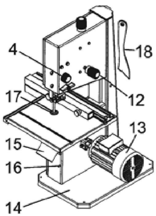
Fig. 1
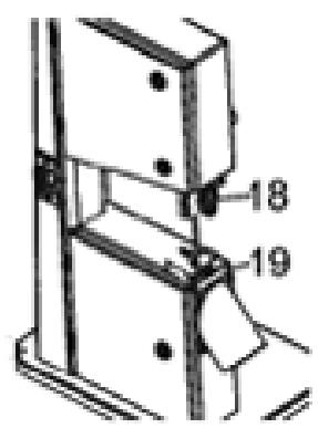
Fig. 2
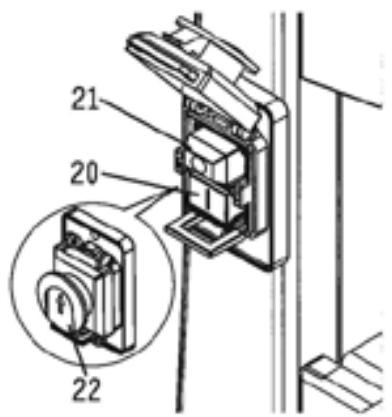
Fig. 3
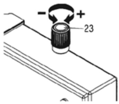
Fig. 4
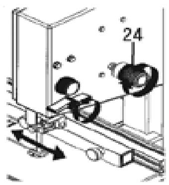
Fig. 5
natural_image
Three abstract geometric shapes with no text or symbols, rendered in grayscale (no text or symbols)Fig. 6
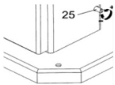
Fig. 7
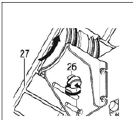
Fig. 8
natural_image
Technical line drawing of a mechanical assembly with no visible text or symbolsFig. 9
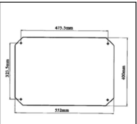
Fig. 10
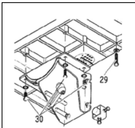
Fig. 11
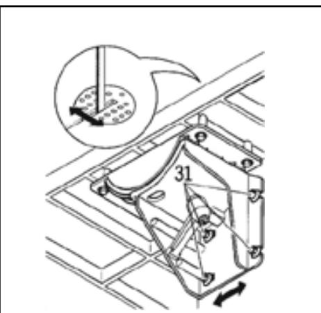
Fig. 12
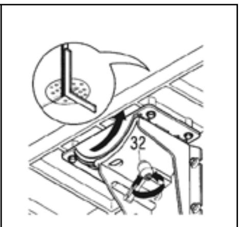
Fig. 13
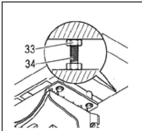
Fig. 14
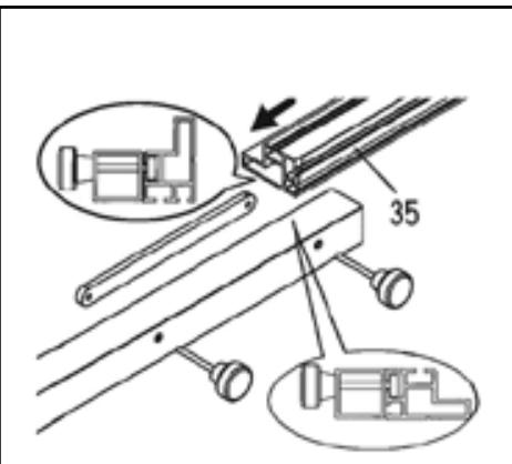
Fig. 15
natural_image
Technical line drawing of a mechanical assembly with no visible text or symbolsFig. 16
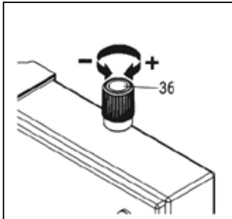
Fig. 17
natural_image
Simple line drawing of a cylindrical object mounted on a flat base with a vertical rod, no text or symbols present.Fig. 18
natural_image
Isometric line drawing of a mechanical assembly with a flat plate and support bracket (no text or symbols)Fig. 19
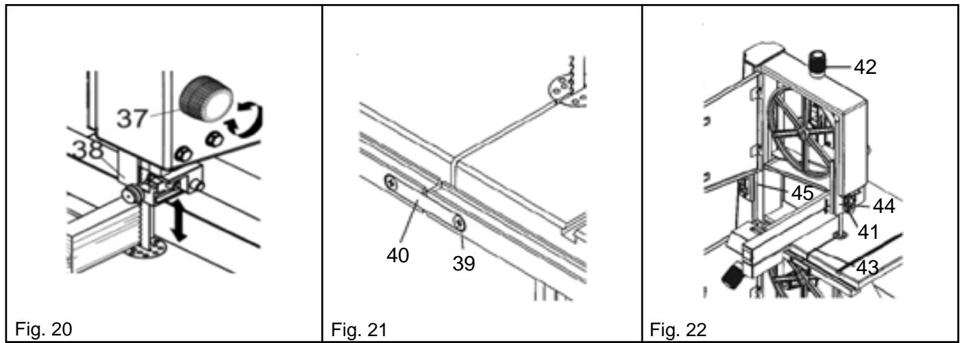
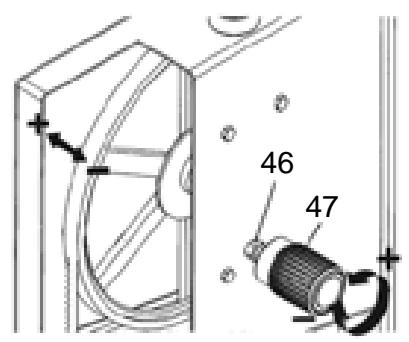
Fig. 23
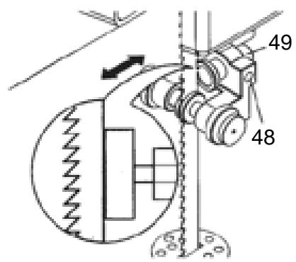
Fig. 24
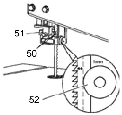
Fig. 25
natural_image
Isometric diagram of a layered structure with a labeled point (69) and no readable text or symbols beyond the label.Fig. 32
natural_image
Technical line drawing of a mechanical assembly with no visible text or symbolsFig. 33
natural_image
Isometric line drawing of a three-legged metal frame structure (no text or symbols)Fig. 34
natural_image
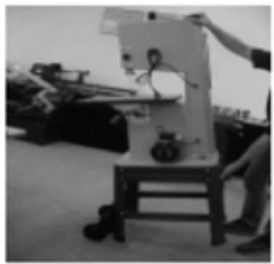
Person operating a mechanical device in a workshop setting (no visible text or symbols)Fig. 35
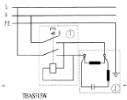
Component list:
1: Switch: KJD20
2: Motor: YKL8014
Fig. 36
1. UN COUP D'ŒIL SUR VOTRE SCIE (Fig. 1)
- Upper door
- Sawblade tension adjustment knob
- Top band saw wheel
- Cut height positioning knob
- Cut height slide
- Sawblade
- Table
- Drive wheel
- Parallel guide
- Lower door
- On/Off switch with emergency stop system
- Upper wheel tilt knob
13.Motor
14.Base - Sawdust extraction outlet
- Transmission belt tension adjustment
- Chip guard
18.Push stick
2. PROPER USE OF YOUR SAW
This machine is designed to cut wood or plastic.
Only cut circles with a proper clamping device through the longitudinal axis of the workpiece because of the risk of twisting of the workpiece by the sawblade.
When you cut boards on edge, use an appropriate set square for safer guiding.
Any other use of this saw is improper. The manufacturer shall under no circumstance be liable for damages resulting for improper use of this saw.
If you modify your saw or use parts that have not been checked and approved by the manufacturer, unpredictable damage may occur when the machine is operating.
2.1 SAFETY PRECAUTIONS
- This machine is an electric tool which can cause severe burns in the event of negligence.
• This is why you must read and comply with: - this instruction manual, paying particular attention to the safety precautions set forth in each section,
- and, where applicable, the legal provisions relative to the handling of band saws.
- Keep all documents provided with this machine in a safe place.
- This machine must only be set up and used by people who are already familiar with band saws and who are constantly conscious of the risks involved in the handling of such tools.
- Minors must only use this machine within the framework of occupational training under the supervision of a specialist.
- The non-appraisable risks referred to above are inherent to band saws and cannot entirely be eliminated by the safety device.
Risks linked to technical modifications made to the machine or the use of parts that were not checked and approved by the manufacturer
- Assemble the machine by scrupulously following the instructions in this manual.
- Only use parts that have been approved by the manufacturer.
- Do not alter the parts in any way.
- Never use the machine when the doors of the sawblade protection mechanism are open.
• Make sure that the sawblade and speed chosen correspond to the material to be sawn. - Do not clean the machine when it is operating.
- Adjust the cleaning brush correctly and clean it on a regular basis.
- For diagonal cuts on a tilted table, mount the parallel guide on the lower table.
- Never use the safety device for transport purposes.
- Utilise the push stick when working on the machine.
Risk associated with the inadvertent start of the machine
- Disconnect the power plug before opening the machine.
- Disconnect the power plug if no-one is using the machine.
Risk associated with environmental factors
- Do not place the machine in the rain or in a damp environment.
• Make sure you have sufficient lighting. Do not use the machine near flammable gas or liquids.
Risks incurred by people in the work area
The machine must only be used by one person at a time. Keep people who are not involved in the work, especially children, outside the work area.
Risk associated with machine failure
Before each start-up, check that the machine, safety device and accessories are not damaged in any way. Do not use the machine if one of the parts is faulty. Immediately replace any defective safety device, cracked or deformed sawblade, or damaged chip guard.
Risk associated with machine instability
If you have long workpieces to cut, use adequate supports for these workpieces on both sides of the machine. Do not lean on the machine.
Make sure that the machine is stable.
Risk associated with foreign matter in the machine
Before each start-up, make sure that there is no object (a tool for example) in the machine.
Risk associated with the opening under the table
For the proper operation of the machine, the sawblade cannot completely be covered under the table. For this reason, you must never put your hands under the table when the machine is operating. You could cut yourself!
Risk associated with inadequate working position or dress
Adopt a good working position. Make sure that no part of your body or clothing can get caught and pulled by the machine.
Risk associated with sawdust
The sawdust of certain woods (like oak and ash) can cause cancer when inhaled. Always work with an extraction device.
This device must meet the following criteria:
- Suited to the external diameter of the extraction outlet
• Air volume > 550 m³/hr
• Suction in the saw extraction outlet > 740 Pa
• Air speed in the saw extraction outlet > 20 m/s
Risk associated with protection system failure
When you work, remember to wear:
- A dust mask
- Ear protection
- Protective eyewear
2.2 SAFETY DEVICE
Upper slide (Fig. 2)
The upper slide (18) protects you from involuntary contact with the sawblade and swirling sawdust. For the upper slide to offer sufficient protection against contacts with the sawblade, the upper sawblade guide must always be at a distance of 3 mm from the workpiece.
Lower slide (Fig. 2)
The lower slide (19) protects you from involuntary contact with the sawblade. When you close the lower door, the lower slide swivels and positions itself in front of the blade.
The lower slide must always be in place when the machine is operating.
3. SPECIFIC FEATURES OF THE PRODUCT
- Grey cast iron table
• High-precision upper guide with three rollers - Cut height gauge
- Longitudinal fence
- Leading-edge technique, resistant and made to last, giving you a sharp and precise cut
• Circular cutting guide
4. TRANSPORTING YOUR SAW
- Place the rack in the lower position.
• Unscrew any protruding accessories.
• If possible, use the factory packaging to pack your saw.
5. CONTROL ELEMENTS
On/Off switch with emergency stop system (Fig. 3)
• To switch on your saw: press on the green button (20).
- To stop your saw: press on the red button (21) or on the cover of the On/Off switch (22).
In the event of a power failure, an undervoltage relay switches on. This ensures that the machine doesn't start on its own when the power comes back. To switch your saw back on, you have to press on the green button again.
The cover of the On/Off switch is an additional safety device on the machine.
Sawblade tension adjustment knob (Fig. 4)
The adjustment knob (23) enables you to alter the tension of the sawblade, if necessary:
• To increase the tension, turn the knob clockwise.
• To reduce the tension, turn the knob counter-clockwise.
Knob to adjust the tilt of the upper wheel of the saw (Fig. 5)
The adjustment knob (24) enables you to alter the tilt of the upper wheel of the saw, if necessary. By changing the tilt setting, adjust the sawblade so that it protrudes from the wheel by the height of one tooth.
- When you turn the adjustment knob clockwise, the sawblade moves back.
- When you turn the adjustment knob counter-clockwise, the sawblade moves forward.
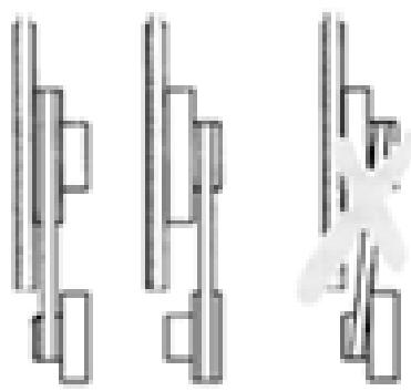
Setting the rotation speed (Fig. 6)
Thanks to the transmission belt tension adjustment, you have two speeds at your disposal:
- 370 m/min for hardwoods and plastics (with an appropriate sawblade)
• 800 m/min for all types of woods
Important!
The transmission belt must not be put in diagonally as this would damage it.
Transmission belt tension adjustment (Fig. 7)
The adjustment knob (25) enables you to alter the tension of the transmission belt, if necessary:
• To reduce the tension, turn the knob clockwise.
• To increase the tension, turn the knob counter-clockwise.
Changing the table tilt setting (Fig. 8)
Once you have loosened the retaining screw (26), you can tilt the table (27) progressively, up to an angle of 45 degrees in relation to the sawblade.
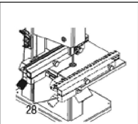
Parallel guide (Fig. 9)
The parallel guide (28) is fixed at the front.
The parallel guide can be mounted either on the left or on the right of the sawblade. When you open the lower door, you must push or move the parallel guide to the right.
6. SETTING UP YOUR SAW
Warning!
Do not start up your saw before the following preparatory measures have been properly carried out:
- Secure the base of the saw.
- Mount and adjust the table.
- Check transmission belt tension.
- Check the safety device.
- Only connect your saw to the mains once all the preparatory measures stated above have been completed! Otherwise you run the risk of the saw starting up inadvertently and causing serious injury.
6.1 SECURING YOUR SAW (Fig. 10)
To ensure the stability of your saw, you must secure it to a flat floor:
- Drill into the floor and insert 4 plugs in it.
- Insert the screws in the base of the saw and screw them down tightly.
The stand (optional accessory) provides optimum working height and stability, also giving the saw its exceptional character.
6.2 MOUNTING THE TABLE (Fig. 11)
- Tighten the dead-stop screw (29) under the table.
- Place the table on the table support.
- Secure the table to the table support using four screws (30).
6.3 ADJUSTING THE TABLE
The table must be adjusted on two levels:
- sideways, so that the sawblade turns in the middle of the chip guard;
• at right angles to the sawblade.
Lateral adjustment of the table (Fig. 12)
- Loosen the four retaining screws (31) of the table support.
- Adjust the table, so that the sawblade is in the middle of the chip guard.
- Tighten the four retaining screws (31).
Right angle adjustment of the table (Fig. 13 - 14)
- Direct the upper blade guiding wheel upwards.
- Check sawblade tension.
- Loosen the retaining screws (32).
- With a set square, adjust the table so that it is at right angles to the blade and tightly screw down the retaining screws (32).
- Loosen the nut (33) and adjust the setting of the dead-stop screw (34) until it touches the saw casing.
- Tighten the nut.
7. MOUNTING THE PARALLEL GUIDE (Fig. 15 - 16)
You can mount the parallel guide either on the right or on the left of the sawblade.
Secure the guide (35) onto the metal part using:
- two knurled screws
- and a slide
7.1 CONNECTING THE SAWDUST EXTRACTION SYSTEM
Warning!
The sawdust of certain woods (like oak and ash) can cause cancer when inhaled. Do not work in confined spaces unless you have a sawdust extraction system (air speed in the extraction outlet > 20 m/s).
Important!
A sawdust extraction system is indispensable unless:
- you work outside.
- you use your saw for a short period of time (30 minutes of use at the most).
• you wear a dust mask.
- When you use your saw without a sawdust extraction system, sawdust builds up: it therefore has to be emptied out on a regular basis.
Connect the extraction system or industrial vacuum cleaner to the sawdust extraction outlet using an appropriate adapter.
7.2 SAWBLADE TENSION (Fig. 17)
Warning!
Too much tension can result in the breakage of the sawblade. Too little tension can result in the sliding of the sawblade.
- Direct the upper blade guiding wheel upwards.
-
If it is necessary to correct the tension:
Turn the adjustment knob (36) clockwise to increase the tension. Turn the adjustment knob (36) counter-clockwise to reduce the tension. -
To check the tension, exert slight lateral pressure on the sawblade, mid-way between the table and the upper sawblade guide (the sawblade must have a maximum sideways give of 1 to 2 mm).
7.3 CONNECTION TO THE MAINS
Warning! Electric voltage
Make sure that the saw is in a dry place. Before you plug in your saw, make sure that the following requirements have been met:
- Fuse protection with FI switch and leakage current of 30 mA
- Mains sockets installed according to professional standards, earthed and approved
Place the power cable so that it is out of your way and will not be damaged while you work.
Protect this cable from heat, corrosive liquids and sharp edges.
Only use rubber cables of a sufficient thickness.
Do not pull on the cable to unplug it from the mains.
8. HANDLING
Warning!
To reduce the risks of injury, follow the safety instructions below while you work:
• Use personal protective equipment:
- A dust mask
- Ear protection
- Protective eyewear
• Never saw more than one workpiece at a time.
- When you saw a workpiece, always maintain it firmly on the table.
- Do not tilt the workpiece. Do not slow down the sawblade by exerting side pressure.
- When your work, if necessary, use:
- A support for large workpieces that may fall off the table once cut.
- A sawdust extraction system.
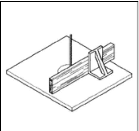
• If you saw boards on edge, use an appropriate set square to prevent your board from tilting. (Fig. 19)
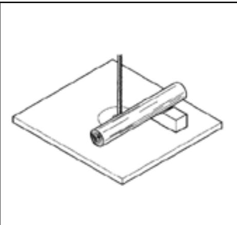
- When you make circular cuts, use an appropriate clamping device to avoid twisting of the workpiece. (Fig. 18)
Before you start working, make sure that the following parts are in perfect condition:
- Sawblade
- Upper and lower slides
- Replace damaged parts immediately.
- Adopt a correct working position when you are sawing (the teeth of the saw must face the user).
- Never saw several workpieces at the same time – never saw joined workpieces made up of several parts. There is a risk of accident if workpieces are pulled by the sawblade while unattended.
Risk associated with inadequate dress
• We advise you not wear loose clothes, jewellery or gloves as they may get caught in the revolving parts of the machine.
• If you have long hair, it is essential that you tie it back.
- Never cut any workpiece which has cables, cords, ribbons, rope or wires attached to it.
Adjusting the height of the upper sawblade guide (Fig. 20)
The height of the upper sawblade guide (38) must be set:
- Before you use the saw, each time you use it, according to the height of the workpiece to be cut (the upper sawblade guide must be approximately 3 mm above the workpiece when it is cut);
- Following each sawblade or table adjustment, change of sawblade, or change of sawblade tension.
Warning!
Before you set the upper sawblade guide and tilt of the table:
• Unplug the machine.
- Wait until the sawblade has stopped.
Using the adjustment knob (37), place the upper sawblade guide (38) in the position desired.
8.1 SETTING THE CUTTING SPEED (Fig. 6)
- Open the lower door.
- Turn the adjustment knob clockwise to loosen the transmission belt.
- Position the transmission belt on the corresponding pulley on the drive wheel (lower wheel of the saw) and on the corresponding motor pulley.
Important!
The transmission belt must be either on the two front pulleys or on the two back pulleys. Never install the transmission pulley diagonally!
If you place the transmission belt on the front pulleys:
• the saw will run at slow speed with high rotating torque.
If you place the transmission belt on the back pulleys:
• the saw will run at high speed with low rotating torque.
-
Tighten the transmission belt by turning the adjustment knob counter-clockwise. (However, the belt must have about 10 mm of give in its middle).
-
Close the lower door.
The instructions concerning the setting of the cutting speed are printed on the plate inside the lower door.
8.2 USING YOUR SAW
- Select and install the chip guard corresponding to the desired type of cut.
- Adjust the blade speed.
- If necessary, adjust the tilt of the table.
- Select the parallel guide and tilt of the table according to the type of cut you want.
- Position the upper sawblade guide 3 mm above the piece to be cut.
Useful tip:
Before sawing, always make a test cut and change the settings if required.
- Place the workpiece on the table.
- Insert the power plug.
- Connect the saw to the mains.
- Saw the workpiece in a single operation.
- Unplug the machine if you cannot continue your work immediately.
9. UPKEEP AND MAINTENANCE
Warning!
Before any upkeep or cleaning operation:
- Unplug the machine.
- Remove the power plug.
- Wait until the saw has stopped.
After your upkeep or cleaning operations, re-set the safety device and check that it is operating properly.
You must always replace damaged parts, especially the safety device, with genuine factory parts since parts that have not been checked and approved by the manufacturer can cause unpredictable damage.
Only qualified staff is authorised to carry out maintenance and repair work other than the operations described in this section.
9.1 CHANGING THE SAWBLADE (Fig. 21 - 22)
Warning!
You can cut yourself even when the sawblade is not moving. Wear gloves to change the sawblade.
Only use appropriate sawblades.
- Loosen the two screws (39) and remove the guide plate (40).
- Open the two doors.
- Direct the upper sawblade guide (41) downwards.
- Loosen the adjustment knob (42) until the sawblade is loose.
- Remove the sawblade and pass the slide through the slit in the table (43) in the upper sawblade guide (44), the sawblade opening (45) and rack.
- Install the new sawblade. Make sure each element is in the correct position: The teeth of the saw must point to the front (towards the door) of the saw.
- Install the sawblade in the middle of the rubber tires.
- Tighten the adjustment knob until the sawblade no longer slides.
-
Close the two doors.
-
Then:
-
Tighten the sawblade (See the section on Setting up your saw).
- Adjust the sawblade (See the section on Upkeep and maintenance).
- Install the rack (See the section on Upkeep and maintenance).
- Run the saw for at least one minute as a test run.
- Unplug the saw, remove the power plug and check the entire set-up once again.
9.2 ADJUSTING THE SAWBLADE (Fig. 23)
If the sawblade is not positioned in the middle of the rubber tires, you have to adjust the tilt of the upper wheel:
- Loosen the nut (46).
- Tighten the set screw (47).
- Turn the set screw (47) clockwise if the sawblade is closer to the front of the saw.
- Turn the set screw (47) counter-clockwise if the sawblade is closer to the back of the saw.
- Tighten the nut (46).
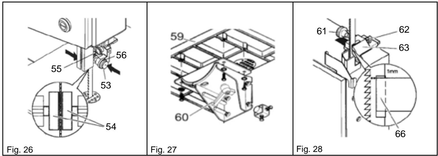
9.3 ADJUSTING THE UPPER SAWBLADE GUIDE (Fig. 24 - 25 - 26)
The upper sawblade guide consists of the following parts:
• A roller (which supports the sawblade from the back)
- Two lateral rollers (which guide the sawblade laterally)
These parts have to be adjusted each time you change or adjust the sawblade.
Useful tip:
- Check the lateral rollers regularly for wear and, when necessary, replace both rollers at the same time.
- By loosening the set screw (48), you can move the roller (49) forwards or backwards in the direction of the arrows.
- Loosen the set screw (50).
- Adjust the three-roller guide (51) so that the lateral rollers (52) are positioned about 1 mm behind the base of the teeth.
- Put the set screw back in (50).
- Loosen the knurled nut (56).
- Place the knurled screw (53) and the lateral rollers (54) in the correct position – the two lateral rollers must be in slight contact with the sawblade.
Turn the wheels of the saw clockwise several times. - Tighten the knurled nut (56).
- Adjust the roller (55) so that it is about 1 mm in front of the sawblade.
- Put the set screw back in (50).
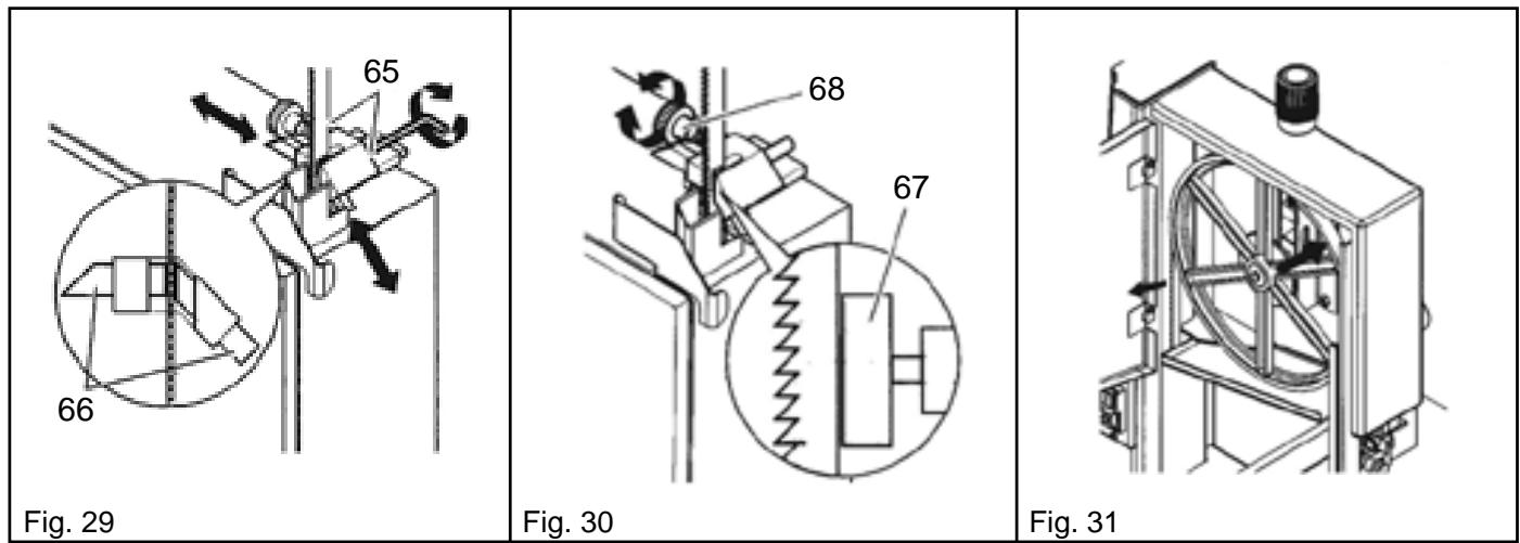
9.4 ADJUSTING THE LOWER SAWBLADE GUIDE (Fig. 21 - 27 - 28 - 29 - 30)
The lower sawblade guide consists of the following parts:
• A roller (which supports the sawblade from the back)
- Two lateral rollers (which guide the sawblade laterally)
These parts have to be adjusted each time you change or adjust the sawblade.
- Loosen the two screws (39) and remove the guide plate (40).
- Unscrew the table (59) from the table support (60).
- Direct the upper sawblade guide upwards.
- Loosen the screw (61), so that the roller can easily move forwards or backwards.
- Loosen the screw (62).
- Adjust the support (63) so that the lateral rollers (66) are positioned about 1 mm behind the base of the teeth.
- Tighten the screw (62).
- Loosen the screw (65) using an Allen key.
- Push the rollers (66) (against the sawblade).
- Turn the wheels of the saw manually several times in a clockwise direction so that the lateral rollers can position themselves correctly – the two lateral rollers must be in slight contact with the sawblade.
- Put the screw back in (65).
- Adjust the roller (67) so that it is in slight contact with the sawblade.
- Put the screw back in (68).
- Securely screw the table back down to the table support.
- Screw back the guide plate to the table.
9.5 CHANGING THE RUBBER TIRES (Fig. 31)
Check the rubber tires regularly for wear. Always replace the rubber tires in pairs.
- Remove the sawblade (See the section on "Upkeep and maintenance").
- Use a small screwdriver to remove the rubber tires.
- Install the new tires and put the sawblade back in.
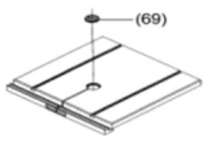
9.6 CHANGING THE CHIP GUARD (Fig. 32)
The chip guard must be changed when the saw track is damaged.
- Remove the chip guard (69) from the table (release it from underneath).
- Install the new chip guard.
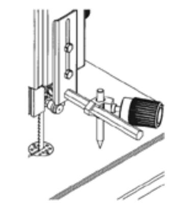
9.7 CIRCULAR CUTTING GUIDE (Fig. 33)
The circular cutting guide can cut cylindrical workpieces with a diameter of up to 260 mm. This device guarantees you optimal cuts when it is used with the curve-cutting sawblade.
- Attach the guide plate with the fastener and screw.
- Install the compass using the locking part and retaining screw.
- Place the circular cutting guide in the desired position.
9.8 STORING YOUR SAW
Warning!
Once your saw has stopped, put your saw away so that incompetent people cannot start it up and so that no-one runs the risk of getting hurt.
Important!
Do not leave the machine outside without protection or in a damp place.
10. A FEW RECOMMENDATIONS
Keep the surface of the table clean – in particular, remove resin residues with an appropriate spray cleaner.
Then treat the surface of the table with a lubricant.
11. REPAIRS
Warning!
Only qualified persons are authorised to repair electrical tools. When you send a part or machine for repair, please describe the defect encountered.
If you have to replace your connecting cable, only use the manufacturer's cable.
12. PROTECTING THE ENVIRONMENT
The material used as packaging for your machine is 100% recyclable.
Used electric tools and accessories contain many precious raw materials and plastics that can be recycled.
This manual is printed on chlorine-free paper.
13. PROBLEMS AND BREAKDOWNS
Warning!
Before any operation on the machine:
- Unplug the machine.
- Remove the power plug.
- Wait until the sawblade has stopped.
After all operations, re-set the safety device and check that it is operating properly.
The motor doesn't work:
The undervoltage relay was set off by a temporary power cut.
Plug the machine back in.
There is no power supply:
Check the state of the cable, plug, socket and fuse.
The motor is over-heating due to a dull sawblade or to sawdust piling up in the casing:
Remove the source of over-heating, let the motor cool down for a few minutes then plug the machine back in.
The sawblade rides outside the cutting line or does not ride correctly:
The sawblade does not ride in the middle of the wheel.
Change the tilt of the upper wheel of the saw.
If the sawblade is distorted, replace it.
The blade is broken:
The sawblade tension is incorrect – adjust it.
Too heavy a load – reduce the pressure on the sawblade.
The blade is distorted: you will get very thin workpieces if the sawblade is too thin and very thick workpieces if the sawblade is too wide.
The blade is buckled:
Too heavy a load – avoid lateral pressure on the sawblade.
The saw vibrates:
The saw is not properly secured; secure the saw correctly to an appropriate floor.
The table is unstable; adjust and secure the table.
The motor mount is unstable; check the state of the retaining screws and tighten them down if necessary.
The sawdust extraction outlet is blocked:
The extraction device has not been connected or the suction capacity is insufficient. Connect the suction device or increase the suction capacity (air speed > 20 m/sec in the sawdust extraction outlet).
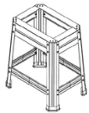
14. ACCESSORIES
1. Stand (Fig. 34)
The stand provides an optimum working height of 1,090 mm.
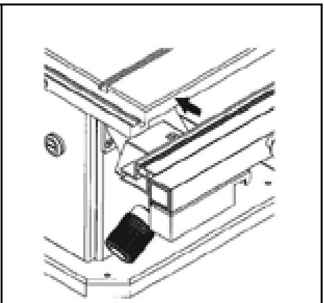
2. Trolley (Fig. 35)
The trolley is ideal for transport purposes. The saw can only be operated on a stand.
15. TECHNICAL DATA
- Model RBS 5518
• Voltage: 230 V (1\~50 Hz)
• Power: 780 Watt
• Current rating 3.5 A
• Fuse: A 10 (delayed action or automatic - K)
• Type of protection IP 54
• Nominal idling speed:1400 + / - 10% min- 1 - Cutting speed:
- Blade speed (fast): 800 + / - 10% m/min
- Blade speed (slow): 370 + / - 10% m/min
- Sawblade size: 2,240 mm
• Throat capacity: 305 mm
• Maximum sawblade width: 15 mm
• Maximum sawblade thickness: 0.5 mm
• Maximum height of cut: 180 mm
• Outside dimensions: 590 x 505 x 1,265 mm
• Weight excluding accessories: 67 kg
• Sound emission levels when idling
A- Sound pressure level LPA: 67 dB(A)
A- Sound power level LPA: 78 dB(A)
• Sound emission levels when sawing:
A- Sound pressure level LPA: 85 dB(A)
A- Sound power level LPA: 91 dB(A)
Useful tip:
The figures mentioned above are emission levels which do not correspond exactly to the sound situation on the work site. While there is a correlation between emission levels and nuisance levels, this does not infer with certitude that additional precautionary measures may be necessary. The factors which currently affect nuisance levels on the work site are: the work space itself as well as the other sources of sound nuisance, such as the number of machines and the number of jobs in progress in the neighbourhood. The authorised sound levels on the work site may also vary from one country to another. These few elements of information should however enable the user to better assess the dangers and risks.
16. CONNECTION DIAGRAM (Fig. 36)
8.1 INDSTILLING AF SAVEHASTIGHED (Fig. 6)
9.8 OPBEVARING AF SAVEN
OBS fare!
7.3 KOBLE SAGBÅNDET TIL STR∅MNETTET
F CE DÉCLARATION DE CONFORMITÉ
GB CE DECLARATION OF CONFORMITY
We declare under our sole responsibility that this product is in conformity with the following standards or standardized documents. EN 61029-1, prEN 61029-2-5, EN 55014-1, EN 55014-2, EN 61000-3-2, EN 61000-3-3 89/336 EWG, 73/23 EWG, 98/37 EG
- UN COUP D'ŒIL SUR VOTRE SCIE (Fig. 1)
- PROPER USE OF YOUR SAW
- SAFETY PRECAUTIONS
- Risks linked to technical modifications made to the machine or the use of parts that were not checked and approved by the manufacturer
- Risk associated with the inadvertent start of the machine
- Risk associated with environmental factors
- Risks incurred by people in the work area
- Risk associated with machine failure
- Risk associated with machine instability
- Risk associated with foreign matter in the machine
- Risk associated with the opening under the table
- Risk associated with inadequate working position or dress
- Risk associated with sawdust
- Risk associated with protection system failure
- SAFETY DEVICE
- Upper slide (Fig. 2)
- Lower slide (Fig. 2)
- SPECIFIC FEATURES OF THE PRODUCT
- TRANSPORTING YOUR SAW
- CONTROL ELEMENTS
- On/Off switch with emergency stop system (Fig. 3)
- Sawblade tension adjustment knob (Fig. 4)
- Knob to adjust the tilt of the upper wheel of the saw (Fig. 5)
- Setting the rotation speed (Fig. 6)
- Important!
- Transmission belt tension adjustment (Fig. 7)
- Changing the table tilt setting (Fig. 8)
- Parallel guide (Fig. 9)
- SETTING UP YOUR SAW
- Warning!
- SECURING YOUR SAW (Fig. 10)
- MOUNTING THE TABLE (Fig. 11)
- ADJUSTING THE TABLE
- Lateral adjustment of the table (Fig. 12)
- Right angle adjustment of the table (Fig. 13 - 14)
- MOUNTING THE PARALLEL GUIDE (Fig. 15 - 16)
- CONNECTING THE SAWDUST EXTRACTION SYSTEM
- SAWBLADE TENSION (Fig. 17)
- CONNECTION TO THE MAINS
- Warning! Electric voltage
- HANDLING
- Risk associated with inadequate dress
- Adjusting the height of the upper sawblade guide (Fig. 20)
- SETTING THE CUTTING SPEED (Fig. 6)
- USING YOUR SAW
- Useful tip:
- UPKEEP AND MAINTENANCE
- CHANGING THE SAWBLADE (Fig. 21 - 22)
- ADJUSTING THE SAWBLADE (Fig. 23)
- ADJUSTING THE UPPER SAWBLADE GUIDE (Fig. 24 - 25 - 26)
- ADJUSTING THE LOWER SAWBLADE GUIDE (Fig. 21 - 27 - 28 - 29 - 30)
- CHANGING THE RUBBER TIRES (Fig. 31)
- CHANGING THE CHIP GUARD (Fig. 32)
- CIRCULAR CUTTING GUIDE (Fig. 33)
- STORING YOUR SAW
- A FEW RECOMMENDATIONS
- REPAIRS
- PROTECTING THE ENVIRONMENT
- PROBLEMS AND BREAKDOWNS
- The sawblade rides outside the cutting line or does not ride correctly:
- The blade is broken:
- The blade is buckled:
- The saw vibrates:
- The sawdust extraction outlet is blocked:
- ACCESSORIES
- Stand (Fig. 34)
- Trolley (Fig. 35)
- TECHNICAL DATA
- CONNECTION DIAGRAM (Fig. 36)
- INDSTILLING AF SAVEHASTIGHED (Fig. 6)
- OPBEVARING AF SAVEN
- KOBLE SAGBÅNDET TIL STR∅MNETTET
- F CE DÉCLARATION DE CONFORMITÉ
- GB CE DECLARATION OF CONFORMITY
Brand : RYOBI
Model : RBS-5518
Category : Band saw