
14138806L - Uncategorized Livarno Lux - Free user manual and instructions
Find the device manual for free 14138806L Livarno Lux in PDF.


| Product Type | LED Recessed Lights (set of 3) |
| Model Number | 14138806L / 14138808L / 14138802L |
| Operating Voltage | 230 V~, 50 Hz |
| Power Consumption | 3 x 5.5 W (total 16.5 W) |
| Dimensions (per light) | Diameter: 82 mm |
| Installation Opening | Diameter: 68 mm |
| Protection Class | II (Double insulated) |
| Light Source Replacement | Not replaceable; entire light must be replaced |
| Dimmability | Dimmable to 3 levels via wall switch (quick successive presses) |
| Minimum Distance Between Lights | 20 cm |
| Installation Clearance (above) | At least 30 mm |
| Installation Clearance (side) | At least 10 cm |
| Required Cable | H03VV-F, min. 2 x 0.75 mm² with wire end ferrules |
| Suitable for | Indoor, dry, enclosed spaces; normally inflammable surfaces |
| Warranty | 36 months from date of purchase |
| Included Items | 3 spotlights, 2 protective tubes, assembly instructions |
| Maintenance | Clean with dry, lint-free cloth only; do not use water or solvents |
| Disposal | Recyclable packaging; do not dispose of product with household waste |
| Safety Warning | Not suitable for external dimmers or electronic switches; risk of burns |
Frequently Asked Questions - 14138806L Livarno Lux
User questions about 14138806L Livarno Lux
0 question about this device. Answer the ones you know or ask your own.
Ask a new question about this device
Download the instructions for your Uncategorized in PDF format for free! Find your manual 14138806L - Livarno Lux and take your electronic device back in hand. On this page are published all the documents necessary for the use of your device. 14138806L by Livarno Lux.
USER MANUAL 14138806L Livarno Lux
Assembly, operating and safety instructions
DE AT CH
LED-EINBAULEUCHTEN
GB Assembly, operating and safety instructions Page 3
Included items Page 5
Technical data....Page 5
Safety Page 5
Safety advice......Page 5
Preparation......Page 7
Required tools and materials......Page 7
Before installation....Page 7
Installation......Page 7
Connecting spotlights to each other....Page 9
Directing the spotlights....Page 10
Dimming the spotlights....Page 10
Maintenance and cleaning......Page 10
Disposal Page 10
Guarantee and service....Page 11
Warranty Page 11
Service address......Page 11
Declaration of conformity....Page 11
Manufacturer......Page 11
| List of pictograms used | |||
 | Please read the operating instructions! |  | Warning!Risk of electric shock |
 | This product is suitable only for use indoors, in dry and enclosed rooms. |  | Prevent fire and injury hazards |
 | Volt (AC) Caution - hot surfaces! |  | |
 | Hertz (frequency) Explosionhazard! |  | |
 | Watt (effective power) |  | Under no circumstances should you cover the spotlights with heat insulating material or similar. |
 | Protection class For your safety |  | |
 | Observe the warnings and safety notices! |  | Dispose of the packaging and device in an environmentally-friendly manner! |
 | Danger to life and risk of accidents for infants and children! |  | Module for installation |
 | This light is not suitable for external dimmers or electronic switches. |  | Switching cycles |
 | LED operating life |  | The packaging is made from 100 % recycled paper. |
LED Recessed Lights
- Introduction

We congratulate you on the purchase of your new device. You have chosen a high quality product. Please read carefully
and completely through these operating instructions. Fold out both pages with the illustrations. These instructions form part of the product and contain important information about bringing the product into use and its handling. Always observe all the safety advice. Check that the correct mains voltage is available and that all the parts have been properly assembled before bringing into use. Should you have
any questions or be uncertain as to how to operate the device, please get in touch with your dealer or service point. Please keep these instructions in a safe place and hand them on to a third party if necessary.
- Proper use

This light is suitable only for interior use, in dry and enclosed spaces. This lamp is intended for use only in a domestic
environment. The light can be fitted to all normally inflammable surfaces.
Included items
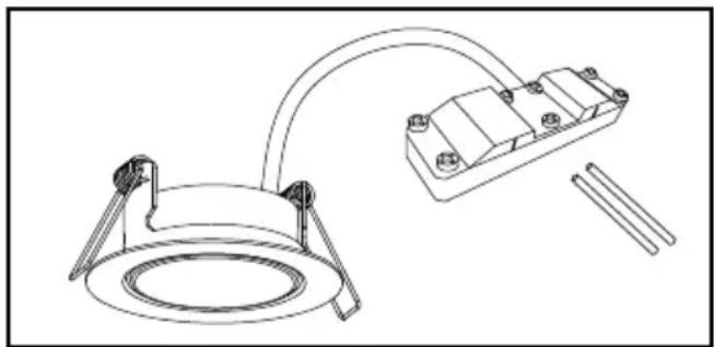
Check that all the items and accessories are present and that the lamp is in perfect condition immediately after unpacking.
3 Installation spotlights
2 Protective tubes
1 Set of assembly instructions and instructions for use
natural_image
Technical line drawing of a mechanical clamp or bracket assembly with two circular components and connecting rods (no text or symbols)- Technical data
Model no.: 14138806L/14138808L/14138802L
Operating voltage: 230V\~, 50Hz
Power consumption: 3 x LED 5.5 W
Dimensions
per round light: ∅ 82 mm
Installation opening: ∅ 68 mm
Protection class: II/
For the cable harness (not supplied) a minimum cross-section of 2 × 0.75 mm^2 is to be used. The corresponding cable is to be provided with wire end ferrules.
● Safety

Safety advice
The right to claim under the guarantee shall be rendered invalid in respect of damage caused by the non-observance of these operating instructions! No liability is accepted for consequent damage! No liability is accepted for damage to property or
persons caused by improper handling or non-observance of the safety advice!


WARNING! RISK OF FATAL INJURY AND ACCIDENT HAZARD FOR TODDLERS AND
SMALL CHILDREN!
Never leave children unsupervised with the packaging materials. The packaging material poses a suffocation hazard. Children frequently underestimate dangers.
This device may be used by children aged 8 years and up, as well as by persons with reduced physical, sensory or mental capacities, or lacking experience and / or knowledge, when supervised or instructed in the safe use of the device and they understand the associated risks. Do not allow children to play with the product. Never allow children to clean or maintain this product unsupervised.

Avoid the risk of fatal injury from electric shock
The electrical installation must be carried out by a qualified electrician or a person trained in electrical installations.
■ Cables with basic insulation and permanent wiring must be provided with additional insulation.
- Use double insulated cables from the connection point to the lamp. The basic insulation must be kept as short as possible so that the basic insulation does not come into contact with the mounting surface or a screw.
- When connecting additional built-in lights, consider the maximum current-carrying capacity of the cables on location. Do not exceed the maximum capacity of the cables.
■ Every time before connecting the lamp the mains, check it and the mains lead for damage. Never use your light if you find it is damaged in any way.
WARNING!
A damaged mains lead presents a serious danger to life from electric shock. In the event of damage, repairs or other problems with the lamp please contact the service centre or an electrician.
Safety
Before installation, remove the fuse for this circuit or switch off at the circuit breaker (O setting) in the fuse box.
Before assembly, ensure that the mains voltage available corresponds to the operating voltage necessary of the light (see "Technical data").
■ Never let the lamp come into contact with water or other liquids.
■ Never open or insert anything into electrical fittings or equipment. Doing this sort of thing can lead to a serious danger to life from electric shock.
- Do not install the lamp on damp or conducting surfaces.
To avoid danger of fire and injury
RISK OF INJURY!
Check every bulb and lampshade for damage immediately upon unpacking. Do not fit the light if the bulbs and / or lampshades are faulty. If they are, contact the service point for a replacement.
CAUTION! RISK OF BURNS

DUE TO HOT SURFACES!
Ensure the lamp has been switched off and allowed to cool before you touch it. In this way you will avoid the danger of burns. Bulbs give off a lot of heat around the top of the lamp.
■ DANGER OF EXPLOSION!

Never use the product in rooms or in the vicinity of easily inflammable or explosive liquids, gases, vapours or dusts.
CAUTION! DANGER OF FIRE!
Never cover the downlights with thermally insu-lative covers or similar materials.
Please ensure there is adequate cooling! The maximum temperature in the downlight installation area of 90 °C must not be exceeded.
- Use the downlight set only with the supplied accessories. Do not interconnect downlight sets. Failure to observe this advice invalidates your rights under the warranty.
- Do not allow the lamp or the packaging materials to lie around unattended. Plastic film or bags, Styrofoam etc. can turn into dangerous toys for children.
Do not look directly into the illuminant (lamp, LED, etc.). Do not look into the illuminant (lamp, LED, etc.) with an optical instrument (e.g. magnifier).
The lamp's light source is not replaceable. The entire light needs to be replaced if the light source reaches the end of its service life.
This light is not suitable for external dimmers or electronic switches.

Working safely
- Install the light so that it is protected from moisture, dirt and the build-up of excessive heat. Do not install the downlights in bathrooms or similar rooms.
■ The distance between two installation spotlights must be at least 20 cm.
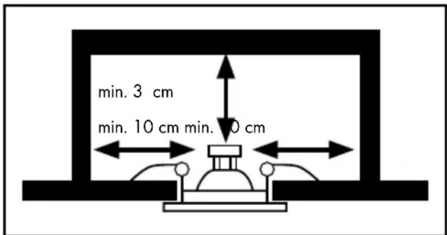
The installation area above the lamp socket must be at least 3 cm and the side clearance at least 10 cm.
■ Make careful preparations for the assembly and take sufficient time. Clearly lay out all components and any additional tools or materials that might be required so that they are readily to hand.
- Remain alert at all times and always watch what you are doing. Always proceed with caution and do not assemble the lamp if you cannot concentrate or feel unwell.
● Preparation
● Required tools and materials
The tools and materials mentioned are not included in the delivery. The details and values given are non-binding and for guidance only. The nature of the material depends on the individual circumstances on site.
- Cable H03VV-F of the required length with wire-end sleeves (minimum diameter 2 x 0.75 mm²)
- Pencil/marking tool
- 2-pole circuit tester
- Screwdriver
- Electric drill
- Hole saw
- Edge cutter
- Ladder
- Before installation
Important: The electrical connection must be carried out by a qualified electrician or someone trained to perform electrical installations. This person must be familiar with the features of the light and the connection requirements.
☐ Familiarise yourself with all instructions and diagrams in this manual as well as with the light before installation.
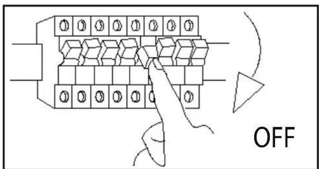
Before installation, ensure that the cable that the light is to be attached to is not live. Remove its fuse or switch off the automatic cutout in the fuse box (0 position).
☐ Check that the power is off using a 2-pole circuit tester.
☐ Only intended for installation outside of normal reach.
- Installation
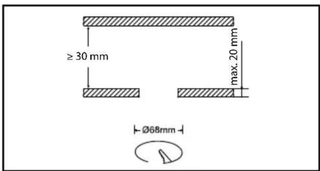
☐ Mark the position of the built-in spotlights. Saw 3 holes into the place you wish to install the spotlight with a keyhole saw (ø 68 mm). Please take into account the distance between two installation spotlights. This must be at least 20 cm. Furthermore, be careful not to damage lines. Only intended for installations out of normal reach.
natural_image
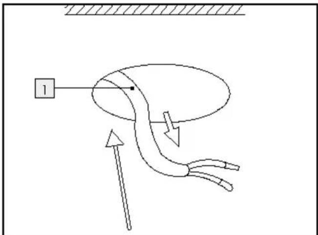
Diagram of a biological or mechanical system with directional arrows and a labeled component (no readable text or symbols)☐ Feed the power cord 1 (external) through the mounting opening.
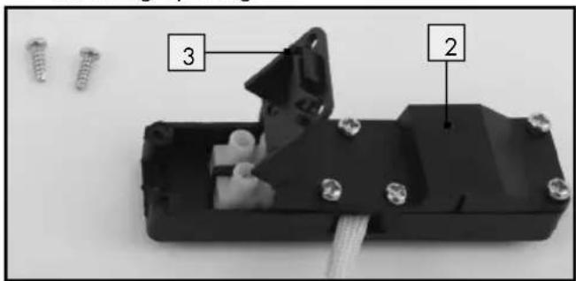
Open the connection box 2 by unscrewing the cover 3 using a screwdriver.
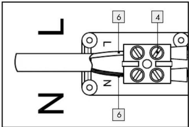
☐ Put the protective tubes 6 over the external power cables.
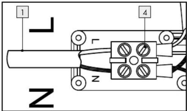
Connect the mains connection cord (external) 1 using the lustre terminal 4. Please note the marking L/N (L = black obrown, N = blue) of the connected wires. Any green / yellow wire which may be present is not connected.
As the light is Protection Class II, earthing of the lamp is not required.
Use a cable of type H03VV-F with a minimum cross-section of 2 x 0.75 mm ^4 and wire end ferrules.
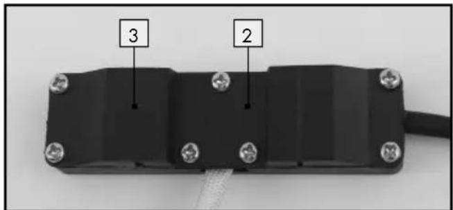
☐ Close the connection box 2 by tightening the cover 3 using a screwdriver.
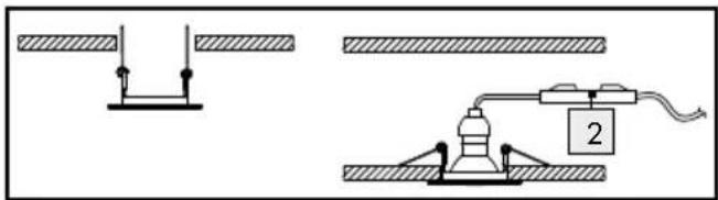
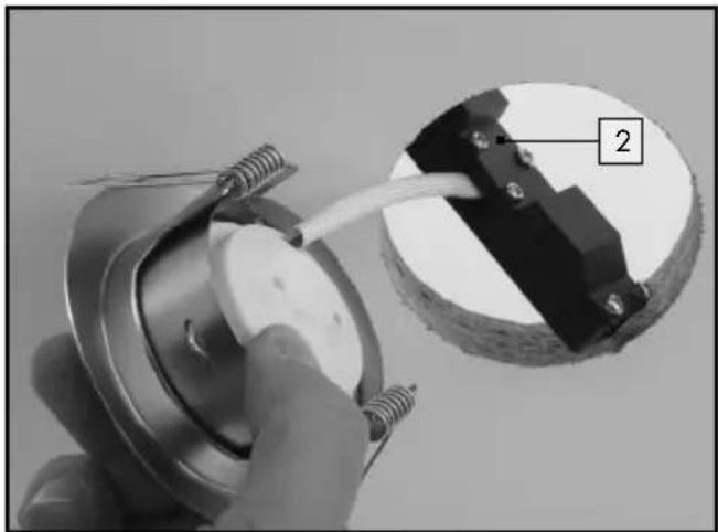
Before fitting the spotlight, remove any insulating material present from the vicinity of the connection box 2 and the spotlight.
natural_image
Close-up of a hand holding a mechanical component with wires, showing a close-up view of a circular component (no text or symbols visible)☐ Push the connection box 2 through the mounting opening.
natural_image
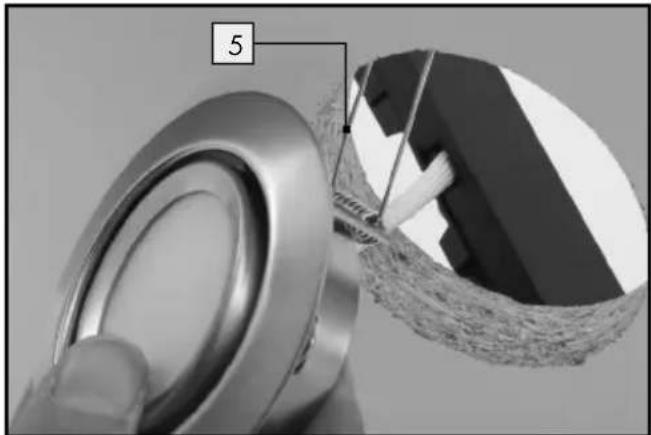
Close-up of a mechanical component with a numbered label '5' pointing to a textured surface (no readable text or symbols)☐ Position the built-in lights diagonally and start by inserting one spring clip 5 into the mounting opening.
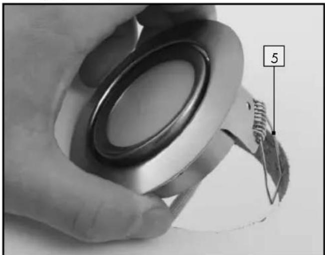
Now insert the second spring clip 5 into the mounting opening.
natural_image
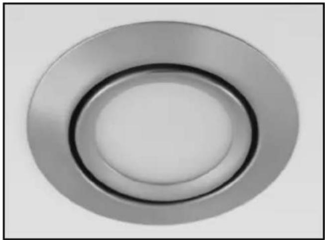
Circular metallic ring component with concentric rings, no text or symbols visible☐ Then press the built-in light completely into the mounting opening. Once they have been pushed in, the retaining springs 5 unfold and in doing so fix the spotlights in place.
Ensure that they are positioned correctly.
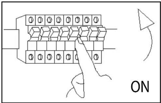
☐ Insert the fuse or switch on the circuit breaker (I setting) inside the fuse box.
Only intended for installation outside of normal reach.
Your light is now ready to use.
●Connectingspotlights to each other
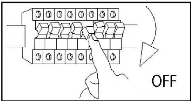
Before installation, ensure that the circuit to which the light will be connected is not energised. To do so, remove the fuse or switch off the circuit breaker in the fuse box (O setting). To check the power is off, use a circuit tester.
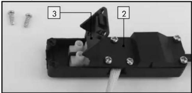
Open the connection box 2 by unscrewing the cover 3 using a screwdriver.
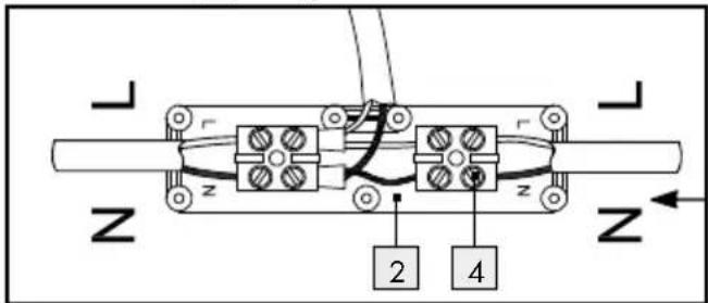
☐ Insert another cable on the other side of the connection box 2.
☐ Connect the cable to the lustre terminal 4. Please note the marking L / N (L = black or brown, N = blue) of the connected wires. Any green / yellow wire which may be present is not connected.
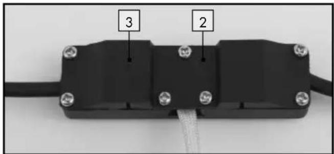
☐ Close the connection box 2 by tightening the cover 3 using a screwdriver.
Before fitting the spotlight, remove any insulating material present from the vicinity of the connection box 2 and the spotlight.
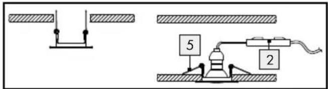
□ Push both of the retaining springs upwards. After pushing in, the retaining springs 5 unfold and in doing so fix the spotlights in place. Ensure that they are positioned correctly. If you would like to connect further spotlights, repeat the steps as described.
- When connecting additional built-in lights, consider the maximum current-carrying capacity of the cables on location. Do not exceed the maximum capacity of the cables.

natural_image
Pure electrical circuit lines without any symbols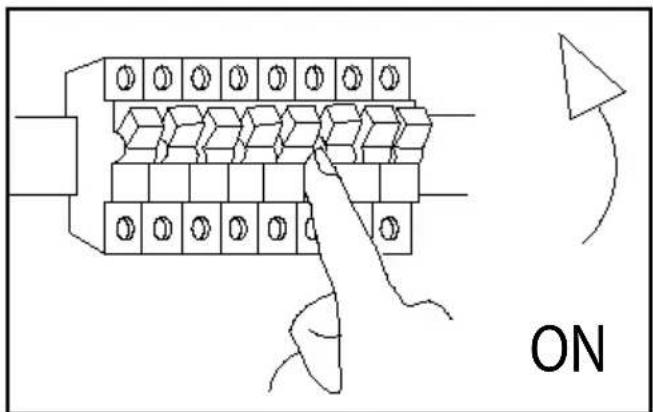
☐ Replace the fuse or switch on the circuit breaker (I setting) inside the fuse box.
Your light is now ready to use.
- Directing the spotlights
■ The spotlights can swivel.
■ To avoid burns, ensure that the light has cooled down completely.
■ To swivel the spotlights, push the internal edge of the spotlight in the desired direction.
Dimming the spotlights
☐ The light bulbs are not suitable for external dimmers or electronic switches.
☐ The lights are provided with a light bulb which is dimmable to 3 different levels.
☐ To dim the light bulb, press the on / off wall switch repeatedly in quick succession.
● Maintenance and cleaning
WARNING! DANGER OF ELECTRIC SHOCK!
Before cleaning the lamp make sure that it is isolated from the mains supply. Remove its fuse or switch off the automatic cutout in the fuse box (0 position).
WARNING! DANGER OF ELECTRIC SHOCK!
For reasons of electrical safety, the light must never be cleaned with water or other fluids or be immersed in water.
Do not use any solvents, petrol or similar. This would cause damage to the light.
☐ Allow the lamp to cool down completely.
☐ When cleaning, only use a dry, lint-free cloth.
- Disposal
The packaging is made entirely of recyclable materials, which you may dispose of at local recycling facilities.
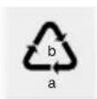
Observe the marking of the packaging materials for waste separation, which are marked with abbreviations (a) and
numbers (b) with following meaning: 1-7: plastics / 20-22: paper and fibre-board/80-98: composite materials.

To help protect the environment, please dispose of the product properly when it has reached the end of its useful life and not in the household waste. Information on collection points and their opening hours can be obtained from your local authority.
● Guarantee and service
Warranty
You receive a 36 month warranty on this product, valid from the date of purchase. The appliance has been carefully produced under strict quality control. Within the warranty period we shall rectify without charge all material and manufacturing defects. In the event of a defect arising during the warranty period, please send the appliance to the listed Service Centre address, making reference to the following item number: 14138806L/14138808L/14138802L. Wear parts (such as bulbs) and damage caused by improper handling, non-observance of the operating instructions or unauthorised interference are excluded from the warranty. The performance of services under the warranty does not extend or renew the warranty period.
Serviceaddress
Please have your receipt and the item number (e.g. IAN 12345) ready as your proof of purchase when enquiring about your product.
• Declaration of conformity CE
This product fulfils the requirements of the applicable European and national directives. Conformity has been demonstrated. The relevant declarations and documents are held by the manufacturer.
Manufacturer
natural_image
Technical line drawing of a mechanical clamp or bracket assembly with mounting holes and wires (no text or symbols)- Technické údaje
Model č.: 14138806L/14138808L/14138802L
natural_image
Diagram of a mechanical or fluid system with a central pipe and directional arrows, no text or symbols present.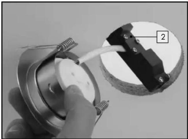
natural_image
Close-up of a hand holding a mechanical component with wires inserted, showing a close-up view of a circular component (no text or symbols visible)natural_image
Close-up of a mechanical component with a numbered label '5' pointing to a section, showing internal structure (no readable text or symbols beyond the number)natural_image
Close-up of a hand holding a metallic mechanical component with a numbered label '5' pointing to a detail (no text or symbols on the object itself)natural_image
Circular metallic ring component with concentric rings, no text or symbols visiblenatural_image
Pure electrical circuit lines without any symbols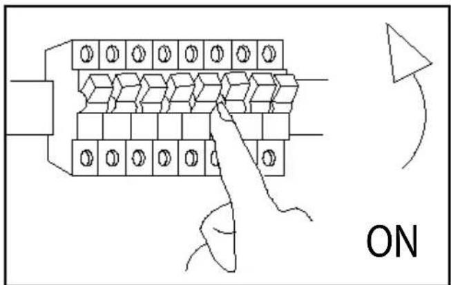
natural_image
Technical line drawing of a mechanical clamp or bracket assembly with two circular components and connecting rods (no text or symbols)- Technische Daten
natural_image
Diagram of a mechanical or fluid system with a curved pipe and directional arrows, no text or symbols present.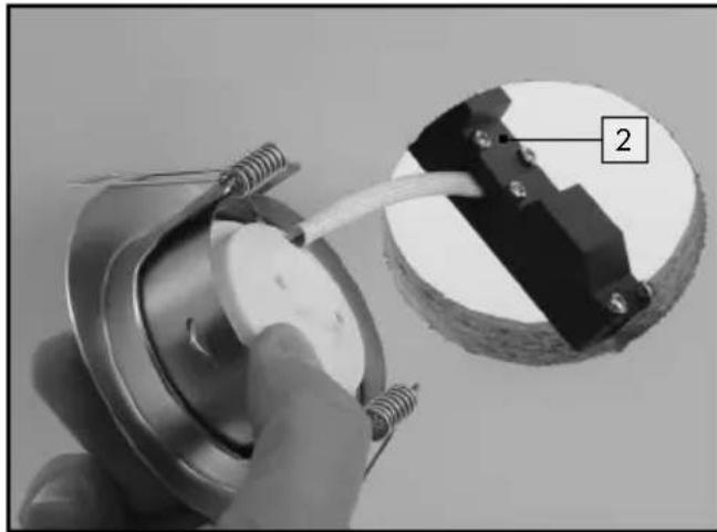
natural_image
Close-up of a hand holding a mechanical component with a cable inserted, showing a circular housing and a numbered label '2' (no readable text or symbols beyond the label)natural_image
Close-up of a mechanical component with a numbered label '5' pointing to a section, showing internal structure (no readable text or symbols beyond label)natural_image
Close-up of a hand holding a mechanical component with a numbered label '5' pointing to a small object (no readable text or symbols beyond the label)natural_image
Circular metallic ring with concentric rings, no text or symbols visiblenatural_image
Pure electrical circuit lines without any symbols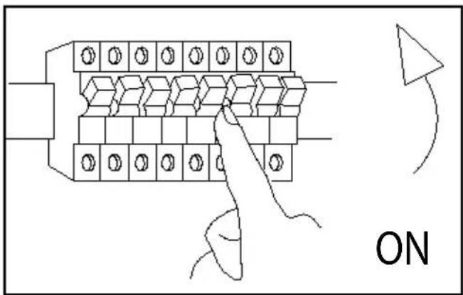


- LED-EINBAULEUCHTEN
- Safety Page 5
- Preparation......Page 7
- Before installation....Page 7
- Installation......Page 7
- Maintenance and cleaning......Page 10
- Disposal Page 10
- Guarantee and service....Page 11
- LED Recessed Lights
- - Introduction
- - Proper use
- Included items
- - Technical data
- ● Safety
- Safety advice
- WARNING! RISK OF FATAL INJURY AND ACCIDENT HAZARD FOR TODDLERS AND
- SMALL CHILDREN!
- Avoid the risk of fatal injury from electric shock
- WARNING!
- Safety
- To avoid danger of fire and injury
- RISK OF INJURY!
- CAUTION! RISK OF BURNS
- DUE TO HOT SURFACES!
- ■ DANGER OF EXPLOSION!
- CAUTION! DANGER OF FIRE!
- Working safely
- ● Preparation
- ● Required tools and materials
- - Before installation
- - Installation
- ●Connectingspotlights to each other
- - Directing the spotlights
- Dimming the spotlights
- ● Maintenance and cleaning
- WARNING! DANGER OF ELECTRIC SHOCK!
- - Disposal
- ● Guarantee and service
- Warranty
- Serviceaddress
- • Declaration of conformity CE
- Manufacturer
- - Technické údaje
- - Technische Daten
Brand : Livarno Lux
Model : 14138806L
Category : Uncategorized